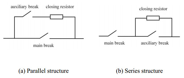
The ultra-high voltage (UHV) AC/DC grid can provide a platform for sustainable power worldwide. To improve the bus voltage quality of the UHV AC system, AC filters are frequently switched into the UHV grid through circuit breakers with pre-insertion resistors. The pre-insertion resistors suppress inrush currents and operate over-voltage during switching. In this paper, we establish a macro and micro model of the pre-insertion resistor based on its temperature coefficient and micro-morphology. We simulate and analyze its electric-thermal coupling characteristics under standard closing and short-circuit faults. After the simulation model and physical comparison analysis, we find that under a usual closing surge, the electric field distribution of the pre-insertion resistor is uniform and undergoes a slight rise in temperature. However, under a short circuit fault, the temperature rise is drastic and exceeds the maximum allowable temperature, causing glassy melt in some parts of the resistor. Considering the volume ratio of each component of the resistor, a two-dimensional cross-sectional simulation model of the resistor is established to simulate the electric-thermal characteristics of the microstructure of the resistor, and insinuates that the current is concentrated in the carbon channel. That is mainly due to the uneven distribution of carbon material and may lead the local temperature to exceed the maximum allowable temperature and damage the resistor.
Citation: Yanyan Bao, Kang Liu, Dingjun Wen, Yifan Li, Hao Wang, Hongliang Zhang. Electrical-thermal coupling characteristics of pre-insertion resistors in AC filter circuit breaker for UHV grid[J]. Mathematical Biosciences and Engineering, 2023, 20(7): 12056-12075. doi: 10.3934/mbe.2023536
The ultra-high voltage (UHV) AC/DC grid can provide a platform for sustainable power worldwide. To improve the bus voltage quality of the UHV AC system, AC filters are frequently switched into the UHV grid through circuit breakers with pre-insertion resistors. The pre-insertion resistors suppress inrush currents and operate over-voltage during switching. In this paper, we establish a macro and micro model of the pre-insertion resistor based on its temperature coefficient and micro-morphology. We simulate and analyze its electric-thermal coupling characteristics under standard closing and short-circuit faults. After the simulation model and physical comparison analysis, we find that under a usual closing surge, the electric field distribution of the pre-insertion resistor is uniform and undergoes a slight rise in temperature. However, under a short circuit fault, the temperature rise is drastic and exceeds the maximum allowable temperature, causing glassy melt in some parts of the resistor. Considering the volume ratio of each component of the resistor, a two-dimensional cross-sectional simulation model of the resistor is established to simulate the electric-thermal characteristics of the microstructure of the resistor, and insinuates that the current is concentrated in the carbon channel. That is mainly due to the uneven distribution of carbon material and may lead the local temperature to exceed the maximum allowable temperature and damage the resistor.

| [1] |
B. Alamri, M. A. Hossain, M. S. J. Asghar, Electric power network interconnection: A review on current status, future prospects and research direction, Electronics, 10 (2021), 2179. https://doi.org/10.3390/electronics10172179 doi: 10.3390/electronics10172179

|
| [2] |
M. Zubair, A. B. Awan, Economic viability of solar energy export from the Middle East and North Africa to Europe and South Asia, Environ. Dev. Sustainability, 23 (2021), 17986–18007. https://doi.org/10.1007/s10668-021-01424-x doi: 10.1007/s10668-021-01424-x
|
| [3] | Z. Zhou, Y. Zhang, W. Wang, Research on the development of UHV-DC technology standardization for global energy interconnection, in 2021 IEEE/IAS Industrial and Commercial Power System Asia (I & CPS Asia), IEEE, (2021), 1278–1284. https://doi.org/10.1109/ICPSAsia52756.2021.9621534 |
| [4] |
K. Strunz, M. Kuschke, S. Schilling, Climate-friendly and socially inclusive AC-DC renewable energy system with overlay multi-terminal HVDC network (OVANET): Solution with fully distributed optimization and infrastructure combination, Int. J. Electr. Power Energy Syst., 132 (2021), 106119, https://doi.org/10.1016/j.ijepes.2020.106119 doi: 10.1016/j.ijepes.2020.106119
|
| [5] | C. Wang, F. Shi, H. Wang, Q. Yang, Optimization design of AC filters for HVDC systems based on improved particle swarm optimization algorithm, in IOP Conference Series: Earth and Environmental Science, IOP Publishing, 453 (2020). https://doi.org/10.1088/1755-1315/453/1/012042. |
| [6] |
Y. Xue, X. P. Zhang, C. Yang, AC filterless flexible LCC HVDC with reduced voltage rating of controllable capacitors, IEEE Trans. Power Syst., 33 (2018), 5507–5518. https://doi.org/10.1109/tpwrs.2018.2800666 doi: 10.1109/tpwrs.2018.2800666
|
| [7] | H. Li, X. Wang, B. Yu, H. Liu, H. Xu, S. Guo, Improved control strategy for AC-filters switching in UHVDC converter station, in IOP Conference Series: Earth and Environmental Science, 192 (2018), 012022. https://doi.org/10.1088/1755-1315/192/1/012022 |
| [8] | Z. Xiong, L. Zhou, Y. Li, D. Ding, W. Lu, Y. Gao, Study on protection logic of last circuit breaker in ultra high voltage converter station, in 2020 5th Asia Conference on Power and Electrical Engineering (ACPEE), (2020), 1651–1656. https://doi.org/10.1109/ACPEE48638.2020.9136325 |
| [9] |
X. Chen, C. He, J. Deng, X. Zhu, G. Zhang, H. Ni, et al., Energization transient suppression of 750 kV AC filters using a pre-insertion resistor circuit breaker with a controlled switching device, IEEE Trans. Power Delivery, 37 (2022), 3381–3390. https://doi.org/10.1109/tpwrd.2021.3128617 doi: 10.1109/tpwrd.2021.3128617
|
| [10] | Q. Xin, X. Zhao, D. Xu, L. Guo, Study on the influence of converter transformer magnetizing inrush current on the low-order AC filter, in 2020 5th Asia Conference on Power and Electrical Engineering (ACPEE), (2020), 1891–1897. https://doi.org/10.1109/ACPEE48638.2020.9136366 |
| [11] |
M. A. Haseeb, M. J. Thomas, Disconnector switching induced transient voltage and radiated fields in a 1100 kV gas insulated substation, Electr. Power Syst. Res., 161 (2018), 86–94. https://doi.org/10.1016/j.epsr.2018.04.001 doi: 10.1016/j.epsr.2018.04.001
|
| [12] |
U. Riechert, W. Holaus, Ultra high-voltage gas-insulated switchgear—a technology milestone, Eur. Trans. Electr. Power, 22 (2012), 60–82. https://doi.org/10.1002/etep.582 doi: 10.1002/etep.582
|
| [13] | K. Chen, Y. Xu, T. Guo, L. Wang, L. Sun, N. Geng, et al., Working principle and testing technology of circuit breaker pre-insertion resistor for 1100kV GIS, in IOP Conference Series: Earth and Environmental Science, 330 (2019), 052006. https://doi.org/10.1088/1755-1315/330/5/052006 |
| [14] |
H. Heiermeier, R. B. Raysaha, Power Testing of pre-insertion resistors: Limitations and Solution, IEEE Trans. Power Delivery, 32 (2017), 1688–1695. https://doi.org/10.1109/tpwrd.2016.2519604 doi: 10.1109/tpwrd.2016.2519604
|
| [15] |
R. Sun, M. McVey, D. Yang, J. R. Stage, A study of synchronous breaker switching with pre-insertion resistor for capacitors banks, IEEE Trans. Power Delivery, 33 (2018), 821–829. https://doi.org/10.1109/tpwrd.2017.2735863 doi: 10.1109/tpwrd.2017.2735863
|
| [16] |
K. A. Bhatt, B. R. Bhalja, U. Parikh, Controlled switching technique for minimization of switching surge during energization of uncompensated and shunt compensated transmission lines for circuit breakers having pre-insertion resistors, Int. J. Electr. Power Energy Syst., 103 (2018), 347–359. https://doi.org/10.1016/j.ijepes.2018.06.024 doi: 10.1016/j.ijepes.2018.06.024
|
| [17] | R. Li, H. Liu, M. Liao, Y. Jing, X. Duan, K. Li, Investigation on transformer inrush current switched by controlled vacuum circuit breaker, in 2018 28th International Symposium on Discharges and Electrical Insulation in Vacuum (ISDEIV), 2 (2018), 563–566. https://doi.org/10.1109/DEIV.2018.8537037 |
| [18] |
K. A. Bhatt, B. R. Bhalja, U. B. Parikh, Evaluation of controlled energisation of an unloaded power transformer for minimising the level of inrush current and transient voltage distortion using PIR-CBs, IET Gener. Transm. Distrib., 12 (2018), 2788–2798. https://doi.org/10.1049/iet-gtd.2017.1825 doi: 10.1049/iet-gtd.2017.1825
|
| [19] | R. Chen, J. Song, L. Hao, Z. Xu, K. Li, W. Chen, et al., Research on mixing process of carbon-ceramic resistor disc for high voltage switchgear, High Voltage Appar., 57 (2021), 196–201. |
| [20] | A. M. Bondar, I. Iordache, P. Svasta, Carbon/ceramic composites designed for electronic application, in 2006 1st Electronic Systemintegration Technology Conference, IEEE, 2 (2006), 708–713. https://doi.org/10.1109/ESTC.2006.280089 |
| [21] | L. Huang, P. Shen, T. Chen, Y. Li, X. Sun, L. Ju, et al., Digital twin modeling and temperature field analysis of transformer windings, in 2022 IEEE 6th Advanced Information Technology, Electronic and Automation Control Conference (IAEAC), (2022), 819–824. https://doi.org/10.1109/iaeac54830.2022.9929698 |
| [22] | Z. Wang, C. L. Bak, H. Sørensen, F. F. da Silva, Q. Wang, Digital twin modeling and simulation of the high-frequency transformer based on electromagnetic-thermal coupling analysis, in 2022 21st IEEE Intersociety Conference on Thermal and Thermomechanical Phenomena in Electronic Systems (iTherm), (2022), 1–7. https://doi.org/10.1109/itherm54085.2022.9899628 |
| [23] |
H. Song, Z. Zhang, J. Tian, G. Sheng, X. Jiang, Multiscale fusion simulation of the influence of temperature on the partial discharge signal of GIS insulation void defects, IEEE Trans. Power Delivery, 37 (2022), 1304–1314. https://doi.org/10.1109/TPWRD.2021.3083736 doi: 10.1109/TPWRD.2021.3083736
|


Figures(17) / Tables(1)

Yanyan Bao, Kang Liu, Dingjun Wen, Yifan Li, Hao Wang, Hongliang Zhang. Electrical-thermal coupling characteristics of pre-insertion resistors in AC filter circuit breaker for UHV grid[J]. Mathematical Biosciences and Engineering, 2023, 20(7): 12056-12075. doi: 10.3934/mbe.2023536


 DownLoad: