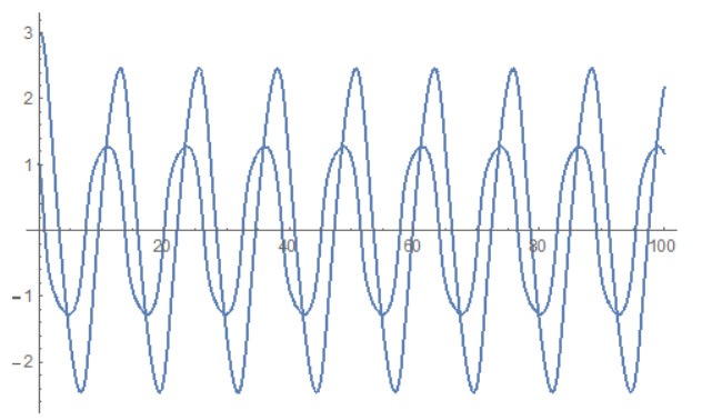
We apply methods from the Koopman operator theory, Extended Dynamic Mode Decomposition and machine learning in the study of business cycle models. We use a simple non-linear dynamical system whose main merit is that in the appropriate parameter space sector predicts intrinsically business cycles which in the phase space are structurally stable limit cycles. Our objective is to approximate this system with a finite dimensional linear model which is defined on some augmented state space. We approximate so the trajectories of the system and obtain an alternative non-perturbative description of the system which can be used for prediction and control. This approach can also be applied to other models as well as to real data.
Citation: John Leventides, Evangelos Melas, Costas Poulios. Extended dynamic mode decomposition for cyclic macroeconomic data[J]. Data Science in Finance and Economics, 2022, 2(2): 117-146. doi: 10.3934/DSFE.2022006
We apply methods from the Koopman operator theory, Extended Dynamic Mode Decomposition and machine learning in the study of business cycle models. We use a simple non-linear dynamical system whose main merit is that in the appropriate parameter space sector predicts intrinsically business cycles which in the phase space are structurally stable limit cycles. Our objective is to approximate this system with a finite dimensional linear model which is defined on some augmented state space. We approximate so the trajectories of the system and obtain an alternative non-perturbative description of the system which can be used for prediction and control. This approach can also be applied to other models as well as to real data.

| [1] |
Angeletos GM, Collard F, Dellas H (2020) Business-Cycle Anatomy. Am Econ Rev 110: 3030–3070. https://doi.org/10.1257/aer.20181174 doi: 10.1257/aer.20181174

|
| [2] | Barsky RB, Sims ER (2011) News Shocks and Business Cycles. J Monetary Econ 58: 273–289. |
| [3] |
Beaudry P, Galizia D, Portier F (2020) Putting the Cycle Back into Business Cycle Analysis. Am Econ Rev 110: 1–47. https://doi.org/10.1257/aer.20190789 doi: 10.1257/aer.20190789
|
| [4] |
Bloom N, Floetotto M, Jaimovich N, et al. (2018) Really Uncertain Business Cycles. Econometrica 86: 1031–1065. https://doi.org/10.3982/ECTA10927 doi: 10.3982/ECTA10927
|
| [5] | Brunton S, Kutz N (2019) Data-Driven Science and Engineering: Machine Learning, Dynamical Systems, and Control. Cambridge University Press. |
| [6] |
Dekimpe MG, Deleersnyder B (2018) Business cycle research in marketing: a review and research agenda. J Acad Mark Sci 46: 31–58. https://doi.org/10.1007/s11747-017-0542-9 doi: 10.1007/s11747-017-0542-9
|
| [7] |
Galí J (1999) Technology, Employment, and the Business Cycle: Do Technology Shocks Explain Aggregate Fluctuations? Am Econ Rev 89: 249–271. https://doi.org/10.1257/aer.89.1.249 doi: 10.1257/aer.89.1.249
|
| [8] | Galí J (2015) Monetary policy, Inflation and the Business Cycle: An Introduction to the New Keynesian Framework and its Applications. Princeton University Press. |
| [9] |
Goodwin RM (1951) The nonlinear accelerator and the persistence of business cycles. Econometrica 19: 1–17. https://doi.org/10.2307/1907905 doi: 10.2307/1907905
|
| [10] | Halmos PR (1951) Introduction to Hilbert space and the theory of spectral multiplicity. Chelsea Publising Company, New York. |
| [11] | Halmos PR, von NJ (1942) Operator methods in classical mechanics, ii. Ann Math 43: 332–350. |
| [12] | Hicks JR (1950) A Contribution to the Theory of the Trade Cycle. Oxford University Press. |
| [13] |
Hua JC, Roy S, McCauley JL, et al. (2015) Using Dynamic Mode Decomposition to Extract Cyclic Behavior in the Stock Market. Phys A 448: 172–180. https://doi.org/10.1016/j.physa.2015.12.059 doi: 10.1016/j.physa.2015.12.059
|
| [14] |
Jaimovich N, Rebelo S (2009) Can News about the Future Drive the Business Cycle? Am Econ Rev 99: 1097–1118. https://doi.org/10.1257/aer.99.4.1097 doi: 10.1257/aer.99.4.1097
|
| [15] |
Justiniano A, Primiceri GE, Tambalotti A (2010) Investment Shocks and Business Cycles. J Monetary Econ 57: 132–145. https://doi.org/10.1016/j.jmoneco.2009.12.008 doi: 10.1016/j.jmoneco.2009.12.008
|
| [16] | Jump RC, Stockhammer E (2022) Building blocks of a heterodox business cycle theory. Working paper 2201, January, Post-Keynesian Economics Society. |
| [17] |
Koopman BO. (1931) Hamiltonian systems and transformation in hilbert space. Proc Natl Acad Sci 17: 315–318. https://doi.org/10.1073/pnas.17.5.315 doi: 10.1073/pnas.17.5.315
|
| [18] |
Korda M, Mezić I (2018) On convergence of extended dynamic mode decomposition to the Koopman operator. J Nonlinear Sci 28: 687–710. https://doi.org/10.1007/s00332-017-9423-0. doi: 10.1007/s00332-017-9423-0
|
| [19] | Kuttichira DP, Gopalakrishman EA, Menon VK, et al. (2017) Analysis of Indian Stock Market Using Dynamic Mode Decomposition. |
| [20] | Kuttichira DP, Gopalakrishman EA, Menon VK, et al.(2017) Stock price prediction using dynamic mode decomposition. International Conference on Advances in Computing, Communications and Informatics (ICACCI). |
| [21] |
Lucas R E (1975) An Equilibrium Model of the Business Cycle. J Polit Econ 83: 1113–1144. https://doi.org/10.1086/260386 doi: 10.1086/260386
|
| [22] |
Mann J, Kutz N (2015) Dynamic Mode Decomposition for Financial Trading Strategies. Quant Financ 16:1643–1655. https://doi.org/10.1080/14697688.2016.1170194 doi: 10.1080/14697688.2016.1170194
|
| [23] |
Mezić I. (2005) Spectral properties of dynamical systems, model reduction and decompositions. Nonlinear Dyn 41: 309–325. https://doi.org/10.1007/s11071-005-2824-x doi: 10.1007/s11071-005-2824-x
|
| [24] |
Mezić I. (2013) Analysis of fluid flows via spectral properties of the koopman operator. Ann Rev Fluid Mech 45: 357–378. https://doi.org/10.1146/annurev-fluid-011212-140652 doi: 10.1146/annurev-fluid-011212-140652
|
| [25] |
Mezić I, Banaszuk A (2004) Comparison of systems with complex behavior. Phys D 197: 101–133. https://doi.org/10.1016/j.physd.2004.06.015 doi: 10.1016/j.physd.2004.06.015
|
| [26] |
Michaillat P, Saez E (2022) An economical business-cycle model. Oxford Econ Pap 74: 382–411. https://doi.org/10.1093/oep/gpab021 doi: 10.1093/oep/gpab021
|
| [27] |
von Neumann J (1932) Zur operatorenmethode in der klassischen mechanik. Ann Math 33: 587–642. https://doi.org/10.2307/1968537 doi: 10.2307/1968537
|
| [28] |
Piiroinen PT, Raghavendra S (2019) A Nonsmooth Extension of Samuelson's Multiplier-Accelerator Model. Int J Bifurcation Chaos 29: 1930027. https://doi.org/10.1142/S0218127419300271 doi: 10.1142/S0218127419300271
|
| [29] | Puu T. (1989) Nonlinear Economic Dynamics. Lecture Notes in Economics and Mathematical Systems 336, Springer-Verlag, Berlin, Heidelberg. |
| [30] |
Rowley CW, Mezić I, Bagheri S, et al.(2009) Spectral analysis of nonlinear flows. J fluid mech 641: 115–127. https://doi.org/10.1017/S0022112009992059 doi: 10.1017/S0022112009992059
|
| [31] |
Samuelson P. (1939) Interactions between the multiplier analysis and the principle of accelaration. Rev Econ Stat 21: 75–78. https://doi.org/10.2307/1927758 doi: 10.2307/1927758
|
| [32] |
Schmid PJ. (2010) Dynamic mode decomposition of numerical and experimental data. Journal of Fluid Mechanics 656: 5–28. https://doi.org/10.1017/S0022112010001217 doi: 10.1017/S0022112010001217
|
| [33] |
Sharma AS, Mezić I, McKeon BJ (2016) Correspondence between koopman mode decomposition, resolvent mode decomposition, and invariant solutions of the navier-stokes equations. Phys Rev Fluids 1: 032402. https://doi.org/10.1103/PhysRevFluids.1.032402 doi: 10.1103/PhysRevFluids.1.032402
|
| [34] |
Williams MO, Kevrekidis IG, Rowley CW (2015) A DataDriven Approximation of the Koopman Operator: Extending Dynamic Mode Decomposition. J Nonlinear Sci 25: 1307–1346. https://doi.org/10.1007/s00332-015-9258-5 doi: 10.1007/s00332-015-9258-5
|
| [35] | Williams MO, Rowley CW, Kevrekidis IG (2015) A kernel approach to data-driven koopman spectral analysis. J Comput Dyn 2: 247–265. |
| [36] |
Williams MO, Rowley CW, Mezić I, et al. (2015) Data fusion via intrinsic dynamic variables: An application of data-driven koopman spectral analysis. EPL (Europhys Lett) 109: 40007. https://doi.org/10.1209/0295-5075/109/40007 doi: 10.1209/0295-5075/109/40007
|


Figures(22)
John Leventides, Evangelos Melas, Costas Poulios. Extended dynamic mode decomposition for cyclic macroeconomic data[J]. Data Science in Finance and Economics, 2022, 2(2): 117-146. doi: 10.3934/DSFE.2022006


 DownLoad: