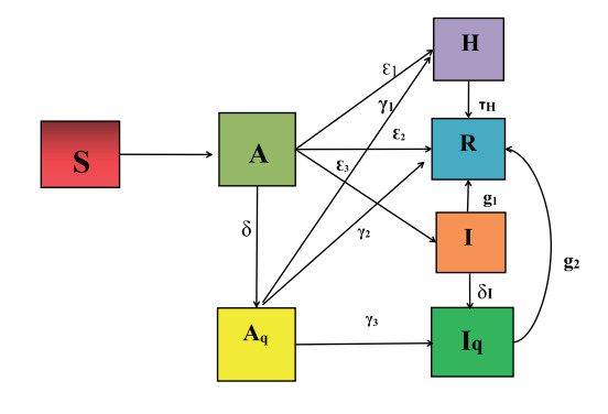
In this study, we propose a Caputo-based fractional compartmental model for the dynamics of the novel COVID-19. The dynamical attitude and numerical simulations of the proposed fractional model are observed. We find the basic reproduction number using the next-generation matrix. The existence and uniqueness of the solutions of the model are investigated. Furthermore, we analyze the stability of the model in the context of Ulam-Hyers stability criteria. The effective numerical scheme called the fractional Euler method has been employed to analyze the approximate solution and dynamical behavior of the model under consideration. Finally, numerical simulations show that we obtain an effective combination of theoretical and numerical results. The numerical results indicate that the infected curve predicted by this model is in good agreement with the real data of COVID-19 cases.
Citation: Saima Akter, Zhen Jin. A fractional order model of the COVID-19 outbreak in Bangladesh[J]. Mathematical Biosciences and Engineering, 2023, 20(2): 2544-2565. doi: 10.3934/mbe.2023119
In this study, we propose a Caputo-based fractional compartmental model for the dynamics of the novel COVID-19. The dynamical attitude and numerical simulations of the proposed fractional model are observed. We find the basic reproduction number using the next-generation matrix. The existence and uniqueness of the solutions of the model are investigated. Furthermore, we analyze the stability of the model in the context of Ulam-Hyers stability criteria. The effective numerical scheme called the fractional Euler method has been employed to analyze the approximate solution and dynamical behavior of the model under consideration. Finally, numerical simulations show that we obtain an effective combination of theoretical and numerical results. The numerical results indicate that the infected curve predicted by this model is in good agreement with the real data of COVID-19 cases.

| [1] |
M. Moriyama, W. J. Hugentobler, A. Iwasaki, Seasonality of respiratory viral infections, Ann. Rev. Virol., 7 (2020), 83–101. https://doi.org/10.1146/annurev-virology-012420-022445 doi: 10.1146/annurev-virology-012420-022445

|
| [2] | WHO COVID-19 Situation Update [online], Avaliable from: https://www.worldometers.info/coronavirus/country/bangladesh/. |
| [3] | World Health Organization (WHO), Avaliable from: https://covid19.who.int/region/searo/country/bd. |
| [4] | Dashboard of John Hopkins University, 2020. Available from: https://coronavirus.jhu.edu/map.html. |
| [5] | Institute of Epidemiology, Disease Control and Research (IEDCR), COVID-19 Status Bangladesh, Available from: https://www.iedcr.gov.bd/. |
| [6] |
H. N. Hasan, M. A. EI-Tawil, A new technique of using homotopy analysis method for solving high-order non-linear differential equations, Math. Methods Appl. Sci., 34 (2011), 728–742. https://doi.org/10.1002/mma.1400 doi: 10.1002/mma.1400
|
| [7] |
S. J. Liao, A kind of approximate solution technique which does not depend upon small parameters: A special example, Int. J. Non-Linear Mech., 30 (1995), 371–380. https://doi.org/10.1016/S0020-7462(96)00101-1 doi: 10.1016/S0020-7462(96)00101-1
|
| [8] |
A. A. Marfin, D. J. Gubler, West Nile encephalitis: An emerging disease in the United States, Clin. Infect. Dis., 33 (2001), 1713–1719. https://doi.org/10.1086/322700 doi: 10.1086/322700
|
| [9] | A. A. Kilbas, H. M. Srivastava, J. J. Trujillo, Theory and Applications of Fractional Differential Equations, North-Holland Mathematics Studies, 2006. https://doi.org/10.1016/S0304-0208(06)80001-0 |
| [10] | A. Hossain, J. Rana, S. Benzadid, G. U. Ahsan, COVID-19 and Bangladesh 2020, 2020. Avaliable from: http://www.northsouth.edu/newassets/images/IT/Covid%20and%20Bangladesh.pdf. |
| [11] | P. V. Driessche, J. Watmough, Reproduction numbers and sub-threshold endemic equilibria for compartmental models of disease transmission, Math. Biosci., 180 (2002), 29–48. http://linkinghub.elsevier.com/retrieve/pii/S0025556402001086 |
| [12] |
M. T. Li, G. Sun, Y. Wu, J. Zhang, Z. Jin, Transmission dynamics of a multi-group brucellosis model with mixed cross infection in public farm, Appl. Math. Comput., 237 (2014), 582–594. https://doi.org/10.1016/j.amc.2014.03.094 doi: 10.1016/j.amc.2014.03.094
|
| [13] | S. M. Jung, Hyers-Ulam-Rassias Stability of Functional Equations in Nonlinear Analysis, Springer, New York, 48 (2011). https://doi.org/10.1007/978-1-4419-9637-4 |
| [14] |
I. A. Baba, D. Baleanu, Awareness as the most effective measure to mitigate the spread of COVID-19 in nigeria, Comput. Mater. Continua, 65 (2020), 1945–1957. https://doi.org/10.32604/cmc.2020.011508 doi: 10.32604/cmc.2020.011508
|
| [15] | Ministry of Home Affairs, Government of Bangladesh, Bangladesh: Total Population from 2017 to 2027, 2022. Available from: https://www.statista.com/statistics/438167/total-population-of-bangladesh/. |


Figures(7) / Tables(2)

Saima Akter, Zhen Jin. A fractional order model of the COVID-19 outbreak in Bangladesh[J]. Mathematical Biosciences and Engineering, 2023, 20(2): 2544-2565. doi: 10.3934/mbe.2023119


 DownLoad: