
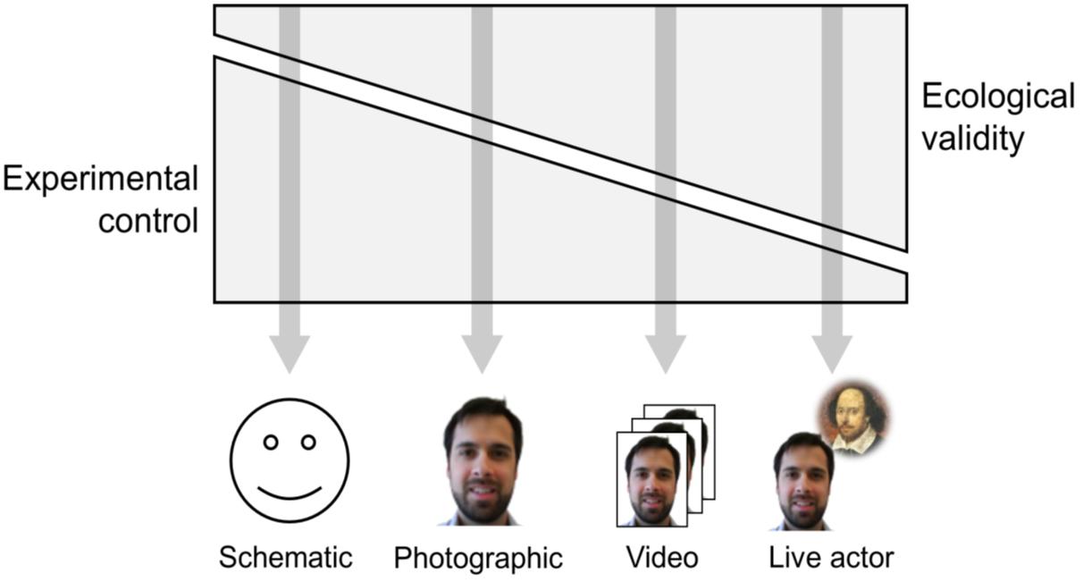
Citation: Fernando Ferreira-Santos. Facial Emotion Processing in the Laboratory (and elsewhere): Tradeoffs between Stimulus Control and Ecological Validity[J]. AIMS Neuroscience, 2015, 2(4): 236-239. doi: 10.3934/Neuroscience.2015.4.236
[1] | Aslak Tveito, Glenn T. Lines, Pan Li, Andrew McCulloch . Defining candidate drug characteristics for Long-QT (LQT3) syndrome. Mathematical Biosciences and Engineering, 2011, 8(3): 861-873. doi: 10.3934/mbe.2011.8.861 |
[2] | Virginia González-Vélez, Amparo Gil, Iván Quesada . Minimal state models for ionic channels involved in glucagon secretion. Mathematical Biosciences and Engineering, 2010, 7(4): 793-807. doi: 10.3934/mbe.2010.7.793 |
[3] | Hongtao Liu, Shuqin Liu, Xiaoxu Ma, Yunpeng Zhang . A numerical model applied to the simulation of cardiovascular hemodynamics and operating condition of continuous-flow left ventricular assist device. Mathematical Biosciences and Engineering, 2020, 17(6): 7519-7543. doi: 10.3934/mbe.2020384 |
[4] | Siqi Chen, Ran Su . An autonomous agent for negotiation with multiple communication channels using parametrized deep Q-network. Mathematical Biosciences and Engineering, 2022, 19(8): 7933-7951. doi: 10.3934/mbe.2022371 |
[5] | Jiuju Shen . EM-TSA: An ensemble machine learning-based transient stability assessment approach for operation of power systems. Mathematical Biosciences and Engineering, 2023, 20(5): 8226-8240. doi: 10.3934/mbe.2023358 |
[6] | Yue Li, Wusheng Xu, Wei Li, Ang Li, Zengjin Liu . Research on hybrid intrusion detection method based on the ADASYN and ID3 algorithms. Mathematical Biosciences and Engineering, 2022, 19(2): 2030-2042. doi: 10.3934/mbe.2022095 |
[7] | Cong Zhao, Na Deng . An actor-critic framework based on deep reinforcement learning for addressing flexible job shop scheduling problems. Mathematical Biosciences and Engineering, 2024, 21(1): 1445-1471. doi: 10.3934/mbe.2024062 |
[8] | T. J. Newman . Modeling Multicellular Systems Using Subcellular Elements. Mathematical Biosciences and Engineering, 2005, 2(3): 613-624. doi: 10.3934/mbe.2005.2.613 |
[9] | Jimin Yu, Jiajun Yin, Shangbo Zhou, Saiao Huang, Xianzhong Xie . An image super-resolution reconstruction model based on fractional-order anisotropic diffusion equation. Mathematical Biosciences and Engineering, 2021, 18(5): 6581-6607. doi: 10.3934/mbe.2021326 |
[10] | Na Pang . Nonlinear neural networks adaptive control for a class of fractional-order tuberculosis model. Mathematical Biosciences and Engineering, 2023, 20(6): 10464-10478. doi: 10.3934/mbe.2023461 |
Since advanced computing technology makes the computational models of cardiac electrophysiology getting mature, the computational models become an important basis for clinical applications [1,2]. Moreover, cardiac cells up to an order of one billion and the internal processes of each cell are also quite complex in the human heart [3]. Therefore, the computational speed, accuracy, and stability are key hotspots in whole heart simulation. Firstly, advanced computer parallelization greatly reduces computing cost of tissue-scale cardiac simulations [4,5,6,7,8]. Secondly, the adaptive algorithms of time-steps and space-steps are a powerful tool for improving the accuracy of computation [6,9,10]. Thirdly, stiffness is ubiquitous in cardiac cell models, which easily leads to unstable computation [11]. Aiming to solve the stiff model of a single cell, the advanced numerical methods of ODEs system, Exponential Adams-Bashforth integrators [12] and Gating-enhanced implicit-explicit linear multistep methods [13] were proposed. In addition, Sundials CVODE [14] is a useful solver for ODEs system. The backward-differentiation-formula (BDF) method in CVODE with low tolerances can obtain a highly converged solution for stiff problems. Due to linear multistep methods consuming high computation cost for high precision solutions, using one-step methods to study the tradeoff between speedup and stability has been a new hot-spot in recent years.
The stability of stiff Markov model for ion channels is our main concern. In recent years, Markovian model for ion channels has been widely used in cardiac arrhythmia [15,16,17] and pharmacologic screening for anti-arrhythmic drugs [18,19]. The introduction of Markov model makes the cell model become quite stiff, resulting in unstable simulation as large time-step is used to accelerate the simulation. Therefore, the confrontation between the computational speed and stability of a single cell is a noticeable problem. To ensure high simulation stability, Johnny Moreira et al. [20] compared UNI with Forward Euler (FE), Rush-Larsen, First-Order Sundnes et al. (SAST1), Second-Order Sundnes et al. (SAST2), and Second-Order Runge-Kutta (RK2) methods and found that UNI could substantially increase the stability of simple first-order (fixed time-step) methods but with very low speedup. Stary et al. [21] proposed the HOS method in comparison to FE and Matrix Rush-Larsen (MRL) methods to show that HOS method could also increase stability with moderate speedup. While, CCL algorithm [22] has been verified to be an efficient method for the stability of the action potential simulation. And our previous work [23] confirmed that CCL algorithm combined with HOS or UNI method could save markedly computation cost and increased the stability of adaptive methods for time-step from 0.001 to 1 millisecond.
For the simulation of cardiac action potential, Marsh et al. [24] proposed that Mixed Root Mean Square(MRMS) errors should be less than 5% to meet the requirement of clinical applications. The simulation results by Chen et al. [23] even with high speed could not meet the accuracy requirement of clinical applications (less than 5% errors). Due to CCL algorithm only adjusts time-steps according to the first and second derivatives of membrane potential, during the period of slow voltage change (from phase 3 to phase 4), the time-step increases rapidly, causing simulation instability of the state variables for the WT-9 model as the state variables still rapidly change their values, resulting in over 5% MRMS errors at simulations of membrane potential and sodium current. For instance, using fixed time-step HOS method as a reference, CCL+HOS solver can get 295 times speedup, but with 22% and 6.9% MRMS errors for potential and sodium current, respectively. The big errors come from large time-step causing the state occupancies of WT-9 model to be simulated unstably at fast inactivation, closed-inactivation and the close states. To eliminate this problem, we propose a multi-variable CCL method that takes the first and second derivatives of membrane potential and state occupancies as input parameters, and then generates the appropriate time-step based on the quadratic equation solution of time-step.
The Markov model of the Wild-Type (WT) sodium channel [18,25] is integrated into the dynamic Luo-Rudy (LRd) model [26]. To simulate the ventricular action potential, the formula is given by,
$ dV/dt=−(1/Cm)(Iion+Ist) $
|
(2.1) |
$ Iion=INa+INa,b+ICa(L),Na+Ins,Na+3INaK+3INaCa+IK+IKi+IKp+ICa(L),K−2INaK+Ins,K+ICa(L)+ICa,b+Ip(Ca)−2INaCa $
|
(2.2) |
where $ I_{st} $ is an external stimulus current, with time-step 0.01 or 0.001 ms with duration 0.5 ms for WT-9 or WT-8 model, respectively. $ I_{Na}, I_{Na, b}, I_{Ca(L), Na}, I_{ns, Na}, 3I_{NaK}, 3I_{NaCa} $ are sodium channel currents. $ I_{K}, I_{Ki}, I_{Kp}, I_{Ca(L), K}, 2I_{NaK}, I_{ns, K} $ are potassium channel currents. $ I_{Ca(L)}, I_{Ca, b}, I_{p(Ca)}, 2I_{NaCa} $ are calcium channel currents. For the detailed descriptions, please see LRd model [26].
The WT-9 Markovian model of the sodium channel includes nine states [25]. Each state is represented by the proportion of channels with respect to the total number of channels called state occupancy. A Markovian model of the WT sodium channel (Figure 1) is composed of one conducting open state ($ {\rm O} $), three closed states ($ {\rm C}_1, {\rm C}_2, {\rm C}_3 $), two closed-inactivation states ($ {\rm IC}_3, {\rm IC}_2 $), one fast inactivation state($ {\rm IF} $) and two intermediate inactivation states ($ {\rm IM}_1, {\rm IM}_2 $). According to the principle of microscopic reversibility[27], the change in one state occupancy with continuous-time is equal to the net flow for the transition state. This change can be represented by an ordinary differential equation (ODE). The WT-9 Markovian sodium channel has nine equations that form a linear system known as Kolmogorov equations.
$ d→u/dt=Q(V)→u $
|
(2.3) |
where $ Q(V) $ is the $ 9\times9 $ matrix of transition rates $ ({\rm af}11, {\rm af}12, {\rm af}13, {\rm af}2, {\rm af}3, {\rm af}4, {\rm af}5, {\rm bt}11, {\rm bt}12, {\rm bt}13, {\rm bt}2, {\rm bt}3, {\rm bt}4, {\rm bt}5) $. $ Q(V) $ is a real matrix of nine rows by nine columns, and it contains elements $ q_{ij} $. $ \overrightarrow{u} $is a vector with nine states $ [{\rm O}, {\rm C}_1, {\rm C}_2, {\rm C}_3, {\rm IC}_3, {\rm IC}_2, {\rm IF}, {\rm IM}_1, {\rm IM}_2]^T $.
The formulation of the sodium channel is described by,
$ INa=¯gNa×O×(V−ENa) $
|
(2.4) |
where $ \overline{g_{Na}} $ is the conductance constant of the sodium channel and $ E_{Na} $ is the equilibrium potential.
A WT-8 Markovian model with eight states of the sodium channel [18] is composed of one conducting open state $ ({\rm O}) $, three closed states $ ({\rm C}_1, {\rm C}_2, {\rm C}_3) $, two closed-inactivation states $ ({\rm IC}_3, {\rm IC}_2) $, one fast inactivation state$ ({\rm IF}) $ and slow inactivation state $ ({\rm IS}) $ shown in Figure 2.
$ Q(V) $ in Eq (2.3) is the $ 8\times8 $ matrix of transition rates $ ({\rm af}11, {\rm af}12, {\rm af}13, {\rm af}2, {\rm af}3, {\rm afx}, {\rm bt}11, {\rm bt}12, {\rm bt}13, {\rm bt}2, {\rm bt}3, {\rm btx}) $. $ Q(V) $ is a real matrix of eight rows by eight columns, and it contains elements $ q_{ij} $. The vector $ \overrightarrow{u} $ includes eight states $ [{\rm O}, {\rm C}_1, {\rm C}_2, {\rm C}_3, {\rm IC}_3, {\rm IC}_2, {\rm IF}, {\rm IS}]^T $.
CCL method is applied to change time-step with membrane potential in simulations. The maximum time-step $ \Delta t_{max} = 1 $ ms and the minimum time-step $ \Delta t_{min} = 0.001 $ ms. Time-step is changed in the scope of $ \Delta t_{min}\thicksim\Delta t_{max} $. To create a fine adaptive time-step, the new approximated membrane potential with second-order Taylor expansion is given by, $ V(t_{n+1}) \cong V(t_n) + dV/dt \times \Delta t + 1/2 \times d^2 V/dt^2 \times \Delta t^2 $. Which can be a quadratic $ \Delta t $ equation used to update time-steps adaptively. For a detailed description, please see Chen et al. [22]. The equation is given by,
$ 1/2×a×Δt2+b×Δt−c≅0,where a=d2V/dt2,b=dV/dt,c=V(tn+1)−V(tn)=±0.1mV $
|
(2.5) |
Let $ D = b^2+4 \times a/2 \times c $, The solutions of Eq (2.5) are shown,
$ Δt=(−b+√D)/a, if b≥0,D≥0, where Δt∈(0.001∼1)ms,c=0.1mV $
|
(2.6) |
$ Δt=(−b−√D)/a, if b<0,D≥0, where Δt∈(0.001∼1)ms,c=−0.1mV $
|
(2.7) |
$ Δt=−b/a, if D<0, where Δt∈(0.001∼1)ms $
|
(2.8) |
$ Δtnew=Minimum(Δt,Δtmax), where Δtmax=Minimum(2×Δtold,Δtmax) $
|
(2.9) |
In addition to membrane potential, the variables control in MCCL method is expanded to multiple variables given by,
$ 1/2×a×Δt2i+b×Δti−c≅0, where a=d2Xi/dt2,b=dXi/dt $
|
(2.10) |
$ c $ is the offset of variable $ X_i $, $ X_i $ is one of the variables $ V_n, {\rm O}, {\rm C}_1, {\rm C}_2, {\rm C}_3, {\rm IC}_3, {\rm IC}_2, {\rm IF}, {\rm IS}, {\rm IM}_1, {\rm IM}_2 $ at $ i^{th} $ time. $ V_n $ is the normalized membrane potential given by, $ V_n = (V-V_{rest})/N_V, {\rm where}\ N_V = |V_{rest}-V_{reversal} | $. $ V_{rest} $ is the membrane potential of rest state, $ V_{reversal} $ is the reversal potential of sodium channel. $ V_{rest} = -88.65 $ mV and $ V_{reversal} = 70.50 $ mV are set respectively. Let $ c = X_i (t_{n+1})-X_i (t_n) = ±0.1/N_V $ and $ D = b^2+4 \times a/2 \times c $, then The solutions of Eq (2.10) are shown,
$ Δti=(−b+√D)/a, if b≥0,D≥0,where Δti∈(Δtmin∼Δtmax)ms,c=0.1/NV $
|
(2.11) |
$ Δti=(−b−√D)/a, if b<0,D≥0,where Δti∈(Δtmin∼Δtmax)ms,c=−0.1/NV $
|
(2.12) |
$ Δti=−b/a, if D<0,where Δti∈(Δtmin∼Δtmax)ms $
|
(2.13) |
$ Δti=Minimum(Δti,Δtmax),where Δtmax=Minimum(2×Δtold,Δtmax) $
|
(2.14) |
$ For WT−9 model,Δtnew=Minimum(ΔtVn,ΔtO,ΔtC1,ΔtC2,ΔtC3,ΔtIC3,ΔtIC2,ΔtIF,ΔtIM1,ΔtIM2) $
|
(2.15) |
$ Or, for WT−8 model,Δtnew=Minimum(ΔtVn,ΔtO,ΔtC1,ΔtC2,ΔtC3,ΔtIC3,ΔtIC2,ΔtIF,ΔtIS) $
|
(2.16) |
Four methods [23] are mainly adopted to solve transient solutions of Eq (2.3) as shown below,
1) Forward Euler method ("FE") and FE method is given by,
$ →u(tn+Δt)=→u(tn)+ΔtQ(V(tn))→u(tn) $
|
(2.17) |
2) Taylor series expansion ("TAL") and second-order Taylor series method is given by,
$ →u(tn+Δt)=→u(tn)+ΔtQ(V(tn))1!→u(tn)+(ΔtQ(V(tn)))22!→u(tn) $
|
(2.18) |
3) Uniformization ("UNI") and the uniformization method by Sidje et al.[28] is given by,
$ →u(tn+Δt)=exp(ΔtQ(V(tn)))→u(tn)≈→u(tn)+ΔtQ(V(tn))1!→u(tn)+⋅⋅⋅+(ΔtQ(V(tn)))ll!→u(tn) $
|
(2.19) |
$ →u(tn+Δt)=exp(qΔtQ(V(tn))∗−I)→u(tn)=exp(−qΔt)exp(qΔtQ(V(tn))∗)→u(tn) $
|
(2.20) |
$ ˉ→u(tn+Δt)=l∑k=0exp(−qΔt)(qΔt)kk!(Q(V(tn))∗)k→u(tn) $
|
(2.21) |
$ l∑k=0exp(−qΔt)(qΔt)kk!≥1−εtol $
|
(2.22) |
$ ˉ→u(tn+Δt)=(exp(−qΔt)exp(qΔtQ(V(tn))∗))m→u(tn) $
|
(2.23) |
where $ m = \lceil\frac{q\Delta t}{\theta}\rceil, h = \frac{\Delta t}{m} $, $ Q(V(t_n))^\ast = I+\frac{Q(V(t_n))}{q}, q = \max|q_{ii}| $. $ q $ is the maximum diagonal element, in absolute value, of matrix $ Q $. $ \varepsilon_{tol} $ denotes the prescribed error tolerance, $ \theta $ and $ m $ are parameters to partition the integral domain for overflow prevention. Two parameters are set in advance, the default $ \varepsilon_{tol} $ is set $ 10^{-11} $ and $ \theta = 1 $ unless otherwise specified. The truncation point $ l $ is determined by Eq (2.22).
4) Hybrid Operator Splitting ("HOS") and HOS method is given by,
$ Q(V(tn))=Q0(V(tn))+Q1(V(tn))+Q2(V(tn)) $
|
(2.24) |
$ →un+1/3=exp(ΔtQ0(V(tn)))→un $
|
(2.25) |
$ →un+2/3=exp(ΔtQ1(V(tn)))→un+1/3 $
|
(2.26) |
$ →un+1=exp(ΔtQ2(V(tn)))→un+2/3 $
|
(2.27) |
For a detailed description, please see Stary et al. [21].
To compare the performance and accuracy between CCL and MCCL methods combined with Markov solver, we have tested eight hybrid solvers, in which each of four methods (FE, TAL, UNI, HOS) is combined with CCL or MCCL method as listed in Table 1. The reference solver is fourth-order four-stage Runge-Kutta (RK4) method used to solve Markov model with fixed time-step ($ \Delta t = 0.001 $ ms). For the very sharply stiff model, BDF (backward-differentiation formula) with tight tolerance and fixed time-step 0.001 ms in Sundials CVODE as a benchmark is an alternative good choice due to high stability even with high computation cost. RK4 with fixed step 0.001 ms has less than 0.6% MRMSE deviation and 10 times smaller computation cost in comparison to BDF with tight tolerance and fixed time-step 0.001 ms in Sundials CVODE.
Solver | Time-steps | Solver | Time-steps |
CCL+FE | (0.001~1 ms) | MCCL+FE | (0.001~1 ms) |
CCL+TAL | (0.001~1 ms) | MCCL+TAL | (0.001~1 ms) |
CCL+UNI | (0.001~1 ms) | MCCL+UNI | (0.001~1 ms) |
CCL+HOS | (0.001~1 ms) | MCCL+HOS | (0.001~1 ms) |
We implement the numerical experiments with Visual Studio 2013 C/C++ compiler. All the numerical tests are performed on a desktop computer equipped with an Intel(R) Core (TM) i7-7700 CPU running 64-bit Windows10 $ \times $ 64. The fixed time-step scheme with RK4 is used as reference solution to evaluate the performance of adaptive time-step schemes with Markov solvers. The Mixed Root Mean Square Error (MRMSE) [24] is used as a metric of quantitative error. It is given by,
$ MRMSE≐√N∑i=1(Xi−ˆXi1+|ˆXi|)2N $
|
(2.28) |
Where $ X_i $ is the numerical solution, $ \hat{X}_i $ is the reference solution, $ N $ is the number of temporal points. All of the numerical schemes run 3000 basic cycle length (BCL) or beats with 1000 ms per BCL or beat. The simulation data are taken from the $ 1^{st} $, $ 500^{th} $, $ 1000^{th} $, $ 1500^{th} $, $ 2500^{th} $, and $ 3000^{th} $ beats.
Table 2 shows the MRMSE and computational performance of the eight schemes for the WT-9 model.
Solvers | MRMSE-V | MRMSE-I | Speedup | Cost(ms) |
DT+RK4 | 0.0 | 0.0 | 1.0X | $ 1.0 \times 10^7 \pm 9.8 \times 10^4 $ |
CCL+FE | 0.016 | 0.588 | 109.9X | $ 9.5 \times 10^4 \pm 4.0 \times 10^2 $ |
CCL+TAL | 0.745 | 1.158 | 33.0X | $ 3.2 \times 10^5 \pm 1.2 \times 10^3 $ |
CCL+UNI | 0.056 | 0.012 | 16.4X | $ 6.4 \times 10^5 \pm 8.4 \times 10^2 $ |
CCL+HOS | 0.236 | 0.064 | 412.3X | $ 2.6 \times 10^4 \pm 3.2 \times 10^2 $ |
MCCL+FE | 0.022 | 0.065 | 96.9X | $ 1.1 \times 10^5 \pm 2.7 \times 10^2 $ |
MCCL+TAL | 0.015 | 0.124 | 29.8X | $ 3.5 \times 10^5 \pm 1.4 \times 10^3 $ |
MCCL+UNI | 0.021 | 0.009 | 14.8X | $ 7.0 \times 10^5 \pm 3.4 \times 10^3 $ |
MCCL+HOS | 0.006 | 0.002 | 17.2X | $ 6.1 \times 10^5 \pm 3.7 \times 10^3 $ |
Note: MRMSE-V: MRMSE of voltage in comparison to the reference. MRMSE-I: MRMSE of sodium current in comparison to the reference. Speedup: The computation cost ratio of one of eight schemes to the reference solution DT+RK4. X, times speedup. Ten simulations for each solver. Cost in Mean ± Standard deviation. |
To meet the requirement of clinical applications, Marsh et al. [24] suggested that MRMSE of simulations should be less than 5%. Table 2 shows that all of CCL combined any Markov solver (FE, TAL, UNI, HOS) do not satisfy the requirement, nor MCCL+FE or MCCL+TAL solver. Only MCCL+UNI and MCCL+HOS solvers can meet the 5% requirement. Particularly, MCCL+HOS solver has less than 1% MRMSEs in voltage and sodium current with 17.2 times (17.2X) speedup which is greater than 14.8X for MCCL+UNI solver. It is suggested that the optimal solver is MCCL+HOS solver among eight solvers in Table 2 for the WT-9 model.
Figure 3 shows the long-term stability (3000 beats) of CCL method or MCCL method combined Markov solvers for Vmax and APD. Figure 3a, e show that both Vmax and APD of MCCL+FE solver have some unstable fine fluctuation, but they are closer to the reference solution than those of CCL+FE solver. Figure 3b, f show that Vmax and APD of MCCL+TAL solver are close to the reference solution with tiny unstable fluctuations, while Vmax and APD of CCL+TAL solver not only have some tiny unstable oscillation but also deviates far from the reference solution. Importantly, Figure 3c, g show that Vmax of CCL+UNI and that of MCCL+UNI solver have a slight error, but remain stable. Figure 3d, h show that the Vmax and APD of MCCL+HOS solver are closer to the reference solution than that of CCL+HOS solver. It is indicated that MCCL method can guarantee long-term stability and obtain more accurate solutions about Vmax and APD than CCL method.
Figure 4 shows the occupancy of nine states of Markov model for CCL or MCCL combined HOS solver at first beat. Figure 4a, c, f–i show that all these state occupancies ($ {\rm O}, {\rm C}_1, {\rm C}_3, {\rm IC}_3, {\rm IM}_1, {\rm IM}_2 $) are close to the reference solution very well for CCL+HOS and MCCL+HOS solvers. While, in Figure 4b shows that the state occupancy $ {\rm IF} $ of MCCL+HOS solver has tiny unstable fluctuation (inset in Figure 4b), but $ {\rm IF} $ of CCL+HOS solver shows a small deviation near 200 ms. Similarly, in Figure 4d, e state $ {\rm C}_2 $ and $ {\rm IC}_2 $ occupancies of MCCL+HOS solver only have very minor fluctuation (insets in Figure 4d, e), while that of CCL+HOS solver presents a deviation error with rapidly descending towards abscissa near 200 ms. It is suggested that MCCL+HOS solver enhances the instability of CCL+HOS solver.
Table 3 shows the MRMSE and computational performance of the eight simulate schemes for the WT-8 model.
Solvers | MRMSE-V | MRMSE-I | Speedup | Cost(ms) |
DT+RK4 | 0.0 | 0.0 | 1.0X | $ 1.1 \times 10^7 \pm 6.0 \times 10^4 $ |
CCL+FE | - - | - - | - - | failure |
CCL+TAL | - - | - - | - - | failure |
CCL+UNI | 0.019 | 0.008 | 1.2X | $ 8.9 \times 10^6 \pm 1.8 \times 10^4 $ |
CCL+HOS | 0.250 | 0.114 | 266.6X | $ 3.3 \times 10^4 \pm 1.3 \times 10^2 $ |
MCCL+FE | 0.103 | 3.345 | 19.8X | $ 5.3 \times 10^5 \pm 2.5 \times 10^3 $ |
MCCL+TAL | - - | - - | - - | failure |
MCCL+UNI | 0.076 | 0.042 | 1.2X | $ 8.9 \times 10^6 \pm 1.1 \times 10^4 $ |
MCCL+HOS | 0.032 | 0.013 | 21.1X | $ 5.0 \times 10^5 \pm 1.8 \times 10^3 $ |
CCL+FE, CCL+TAL and MCCL+TAL solvers are the failure, while MCCL+FE solver is success but with MRMSE higher than 5%. Only CCL+UNI and MCCL+HOS solvers have MRMSE-V and MRMSE-I less than 5%. CCL+UNI solver almost takes no speedup, while MCCL+HOS solver still obtains 21.1 times speedup. For WT-8 model, MCCL+HOS solver is the best solver among eight solvers in Table 3.
Due to an enormous maximum time-step size, $ \Delta t_{max} $, used by CCL and MCCL algorithms, the simulation is prone to instability and even divergence to failure for CCL and MCCL combined with FE or TAL, especially for WT-8 model. It is improper to use FE or TAL combined with adaptive time-step methods unless a smaller maximum time-step size, $ \Delta t_{max} $, is used but then the adaptivity of the method is limited.
In Tables 2 and 3, the speedup performance of MCCL+UNI and CCL+UNI solvers is similar since the UNI algorithm consumes most of the computation time. The formula (2.23) is iterated 260 times with $ q = 260 $ for the WT-8 model to reach the preset tolerant error even time-step is set as 1ms. As a result, there is almost no speedup of MCCL or CCL combined with UNI for WT-8 model.
While, the speedup of MCCL+HOS and CCL+HOS solvers is significant due to HOS being lightweight. CCL+HOS solver gets high over 250 times speedup for WT-8 and WT-9 models while MCCL+HOS only gets about 20 times. However, CCL+HOS solver has large MRMSE for WT-9 model and even 25% MRMSE for WT-8 failing the clinical application requirement. While MCCL+HOS solver has MRMSEs less than 5% clinical application requirement even with lower speedup.
In our previous work [23], we find that CCL+UNI solver is the most stable but very time-consuming while CCL+HOS solver is less stable but more efficient. It is suggested the optimal solver should take tradeoff between stability and acceleration. In this work, the MCCL+HOS solver is more stable, more accurate and faster than MCCL+UNI solver. For the WT-8 model, CCL+UNI solver is the most accurate but has poor speedup performance (only 1.2X). It is concluded that MCCL+HOS solver is a good solver, especially for high stiff Markov model such as WT-8 sodium channel and MCCL instead of CCL can be a good speedup algorithm tradeoff for stability against acceleration.
Both CCL and MCCL have their limitations in which the speedup of MCCL+HOS solver is far less than CCL+HOS while the accuracy of CCL+HOS is far worse than MCCL+HOS. To achieve better accuracy, MCCL+HOS is highly recommended but its speedup performance is only moderate and, importantly, the speedup performance is about the same for moderate stiff WT-9 and high stiff WT-8 models. It is highly recommended to use MCCL+HOS for a high stiff model, but for moderate stiff model MCCL+HOS should be revised to gain higher speedup for the logic of lower stiff higher speedup performance in the near future.
This work was supported by Sun Yat-sen University, China, under Scientific Initiation Project [No.67000-18821109] for High-level Experts and by the Ministry of Science and Technology, Taiwan, under grant 107-2115-M-006-013 separately.
The authors declare that they have no conflict of interest.
[1] | Maratos FA, Garner M, Hogan AM, et al. (2015) When is a Face a Face? Schematic Faces, Emotion, Attention and the N170. AIMS Neurosci 2: 172-182. |
[2] |
Krombholz A, Schaefer F, Boucsein W (2007) Modification of N170 by different emotional expression of schematic faces. Biol Psychol 76: 156-162. doi:10.1016/j.biopsycho.2007.07.004 doi: 10.1016/j.biopsycho.2007.07.004
![]() |
[3] |
Almeida PR, Ferreira-Santos F, Vieira JB, et al. (2014) Dissociable effects of psychopathic traits on cortical and subcortical visual pathways during facial emotion processing: An ERP study on the N170. Psychophysiology 51: 645-657. doi:10.1111/psyp.12209 doi: 10.1111/psyp.12209
![]() |
[4] |
Sato W, Kochiyamab T, Yoshikawab S, Naitoa E, et al. (2004) Enhanced neural activity in response to dynamic facial expressions of emotion: an fMRI study. Brain Res Cogn Brain Res 20: 81-91. doi:10.1016/j.cogbrainres.2004.01.008 doi: 10.1016/j.cogbrainres.2004.01.008
![]() |
[5] |
Pönkänen LM, Alhoniemi A, Leppaänen JM, et al. (2011) Does it make a difference if I have an eye contact with you or with your picture? An ERP study. Soc Cogn Affect Neurosci 6: 486-494. doi:10.1093/scan/nsq068 doi: 10.1093/scan/nsq068
![]() |
[6] |
Gramann K, Ferris DP, Gwin J, et al. (2014) Imaging natural cognition in action. Int J Psychophysiol 91: 22-29. doi:10.1016/j.ijpsycho.2013.09.003 doi: 10.1016/j.ijpsycho.2013.09.003
![]() |
[7] | Makeig S, Gramann K, Jung T-P, et al. (2009) Linking brain, mind and behavior: The promise of mobile brain/body imaging (MoBI). Int J Psychophysiol 73: 985-100. |
1. | Ning He, Changyou Tang, Xianchao Zhou, Shuolin Feng, M Pallikonda Rajasekaran, Diagnostic Value of Magnetic Resonance Image Feature Analysis under Reconstruction Algorithm for Knee Epiphyseal Injury, 2022, 2022, 1875-919X, 1, 10.1155/2022/1783975 |
Solver | Time-steps | Solver | Time-steps |
CCL+FE | (0.001~1 ms) | MCCL+FE | (0.001~1 ms) |
CCL+TAL | (0.001~1 ms) | MCCL+TAL | (0.001~1 ms) |
CCL+UNI | (0.001~1 ms) | MCCL+UNI | (0.001~1 ms) |
CCL+HOS | (0.001~1 ms) | MCCL+HOS | (0.001~1 ms) |
Solvers | MRMSE-V | MRMSE-I | Speedup | Cost(ms) |
DT+RK4 | 0.0 | 0.0 | 1.0X | $ 1.0 \times 10^7 \pm 9.8 \times 10^4 $ |
CCL+FE | 0.016 | 0.588 | 109.9X | $ 9.5 \times 10^4 \pm 4.0 \times 10^2 $ |
CCL+TAL | 0.745 | 1.158 | 33.0X | $ 3.2 \times 10^5 \pm 1.2 \times 10^3 $ |
CCL+UNI | 0.056 | 0.012 | 16.4X | $ 6.4 \times 10^5 \pm 8.4 \times 10^2 $ |
CCL+HOS | 0.236 | 0.064 | 412.3X | $ 2.6 \times 10^4 \pm 3.2 \times 10^2 $ |
MCCL+FE | 0.022 | 0.065 | 96.9X | $ 1.1 \times 10^5 \pm 2.7 \times 10^2 $ |
MCCL+TAL | 0.015 | 0.124 | 29.8X | $ 3.5 \times 10^5 \pm 1.4 \times 10^3 $ |
MCCL+UNI | 0.021 | 0.009 | 14.8X | $ 7.0 \times 10^5 \pm 3.4 \times 10^3 $ |
MCCL+HOS | 0.006 | 0.002 | 17.2X | $ 6.1 \times 10^5 \pm 3.7 \times 10^3 $ |
Note: MRMSE-V: MRMSE of voltage in comparison to the reference. MRMSE-I: MRMSE of sodium current in comparison to the reference. Speedup: The computation cost ratio of one of eight schemes to the reference solution DT+RK4. X, times speedup. Ten simulations for each solver. Cost in Mean ± Standard deviation. |
Solvers | MRMSE-V | MRMSE-I | Speedup | Cost(ms) |
DT+RK4 | 0.0 | 0.0 | 1.0X | $ 1.1 \times 10^7 \pm 6.0 \times 10^4 $ |
CCL+FE | - - | - - | - - | failure |
CCL+TAL | - - | - - | - - | failure |
CCL+UNI | 0.019 | 0.008 | 1.2X | $ 8.9 \times 10^6 \pm 1.8 \times 10^4 $ |
CCL+HOS | 0.250 | 0.114 | 266.6X | $ 3.3 \times 10^4 \pm 1.3 \times 10^2 $ |
MCCL+FE | 0.103 | 3.345 | 19.8X | $ 5.3 \times 10^5 \pm 2.5 \times 10^3 $ |
MCCL+TAL | - - | - - | - - | failure |
MCCL+UNI | 0.076 | 0.042 | 1.2X | $ 8.9 \times 10^6 \pm 1.1 \times 10^4 $ |
MCCL+HOS | 0.032 | 0.013 | 21.1X | $ 5.0 \times 10^5 \pm 1.8 \times 10^3 $ |