
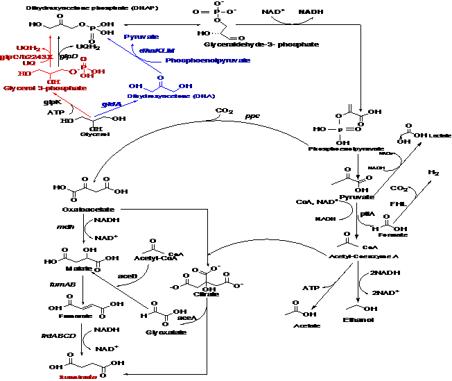
Citation: Bashir Sajo Mienda, Mohd Shahir Shamsir. Model-driven in Silico glpC Gene Knockout Predicts Increased Succinate Production from Glycerol in Escherichia Coli[J]. AIMS Bioengineering, 2015, 2(2): 40-48. doi: 10.3934/bioeng.2015.2.40
[1] | Hakkee Jung . Analytical subthreshold swing model of junctionless elliptic gate-all-around (GAA) FET. AIMS Electronics and Electrical Engineering, 2024, 8(2): 211-226. doi: 10.3934/electreng.2024009 |
[2] | Hakkee Jung . Analysis of drain induced barrier lowering for junctionless double gate MOSFET using ferroelectric negative capacitance effect. AIMS Electronics and Electrical Engineering, 2023, 7(1): 38-49. doi: 10.3934/electreng.2023003 |
[3] | Hakkee Jung . Analytical models of threshold voltage and drain induced barrier lowering in junctionless cylindrical surrounding gate (JLCSG) MOSFET using stacked high-k oxide. AIMS Electronics and Electrical Engineering, 2022, 6(2): 108-123. doi: 10.3934/electreng.2022007 |
[4] | K Srilatha, B T P Madhav, J Krishna, Y V N R Swamy Banothu, Anil Badisa . Design of electromagnetic cloak with sequentially connected rectangular split ring resonators for S-band applications. AIMS Electronics and Electrical Engineering, 2022, 6(4): 385-396. doi: 10.3934/electreng.2022023 |
[5] | Tadele A. Abose, Fanuel O. Ayana, Thomas O. Olwal, Yihenew W. Marye . BER performance analysis of polar-coded FBMC/OQAM in the presence of AWGN and Nakagami-m fading channel. AIMS Electronics and Electrical Engineering, 2024, 8(3): 311-331. doi: 10.3934/electreng.2024014 |
[6] | Jeevani W. Jayasinghe . Application of Genetic Algorithm for Binary Optimization of Microstrip Antennas: A Review. AIMS Electronics and Electrical Engineering, 2021, 5(4): 315-333. doi: 10.3934/electreng.2021016 |
[7] | Habib Hadj-Mabrouk . Analysis and prediction of railway accident risks using machine learning. AIMS Electronics and Electrical Engineering, 2020, 4(1): 19-46. doi: 10.3934/ElectrEng.2020.1.19 |
[8] | Simona Miclaus, Delia-Bianca Deaconescu, David Vatamanu, Andreea Maria Buda, Annamaria Sarbu, Bogdan Pindaru . Peculiarities of the radiated field in the vicinity of a mobile terminal connected to 4G versus 5G networks during various applications usage. AIMS Electronics and Electrical Engineering, 2022, 6(2): 161-177. doi: 10.3934/electreng.2022010 |
[9] | Manisha R. Bansode, Surendra S. Rathod . A bandwidth enhanced multilayer electromagnetic bandgap structure to reduce the simultaneous switching noise. AIMS Electronics and Electrical Engineering, 2023, 7(4): 406-420. doi: 10.3934/electreng.2023021 |
[10] | Patrick Seeling . Augmented Reality Device Operator Cognitive Strain Determination and Prediction. AIMS Electronics and Electrical Engineering, 2017, 1(1): 100-110. doi: 10.3934/ElectrEng.2017.1.100 |
The planar-type MOSFETs are no longer available due to Short Channel Effects (SCEs), such as an increase in subthreshold swing, off-current, threshold voltage roll-off and Drain Induced Barrier Lowering (DIBL) as the transistor size decreases [1,2,3]. The FinFET structure, which is a tri-gate structure used to solve this problem, also has limitations in scaling, so a transistor with a new structure has been developed [4,5,6]. In particular, FinFET using ferroelectric was developed to solve the increase in power consumption, which is the most problematic due to the reduction in transistor size, which is indispensable for high-speed operation [7,8]. Also, a Gate-All-Around (GAA) FET is being developed as a next-generation transistor structure to overcome the limitations of FinFETs [9,10]. The GAA FET has a structure that maximizes the ability of the gate to control the channel carrier, and numerous studies are currently being conducted on these devices [11,12]. In particular, the junctionless structure [13,14], which makes the doping concentration of the channel and the source/drain region almost the same, is applied to the GAA FET structure as a structure that can solve the difficulty of manufacturing due to the reduction in transistor size [15,16,17].
In addition, to achieve low power consumption, it is also necessary to reduce the subthreshold swing (SS). To overcome the limit of 60 mV/dec for the SS, ferroelectric materials are used, for which Metal-Ferroelectric-Insulator-Semiconductor (MFIS) structures and Metal-Ferroelectric- Metal-Insulator-Semiconductors (MFMIS) are mainly used [18,19]. Compared to the MFMIS structure, the stability of the ferroelectric material in the MFIS structure is independent of the gate leakage current, but gate leakage is ignored in this paper, so an analytical model of subthreshold swing is presented for the junctionless GAA FET of the MFMIS structure with high on-current. Research has been conducted extensively on junction-based MFIS-structured GAA FETs [20,21], but little has been done on junctionless MFMIS-structured GAA FETs.
Rassekh et al. analyzed SCEs such as the SS and DIBL for a channel length of 100 nm for the MFMIS-structured double-gate junctionless FET with ferroelectric [22]. It was found that the change of SS for the ferroelectric thickness could not be observed in the deep subthreshold region when the channel length was about 100 nm. Pahwa et al. analyzed the threshold voltage roll-off, SS, DIBL, etc. up to 10 nm channel length for undoped channel double gate FETs with MFIS and MFMIS structures, but they only used numerical simulation [23]. Sakib et al. analyzed SCEs for ferroelectric GAA FETs, but only numerically simulated junction-based MFIS and MFMIS structures [24]. Choi et al. and Raut et al. analyzed SCEs for junctionless GAA FET using ferroelectric, but only used TCAD [25,26]. Mehta et al., Gaidhane et al. and Kim et al. analyzed the current-voltage characteristics of the ferroelectric MFIS structure, but analyzed only one-dimensionally for the channel radial direction of the long-channel, so the change of SS occurring in the short channel could not be interpreted [27,28,29]. It is necessary, however, to analyze not only the potential distribution along the radial direction of the channel but also along the channel length direction as the size of the transistor decreases. To this end, it is necessary to solve the two-dimensional Poisson equation in the GAA structure. In addition, in the junctionless GAA structure using ferroelectric, it is necessary to know how the charge in the ferroelectric changes according to the gate voltage to interpret the SS in the junctionless GAA FET with ferroelectric. Therefore, in this paper, we will find the solution of Poisson's equation two-dimensionally for the junctionless GAA FET of cylindrical structure with ferroelectric, and derive the drain current-gate voltage relationship using it. From the current-voltage relationship obtained in this way, we will find SS according to the definition of SS and compare it with the value of the analytical SS model presented. Ferroelectric will use the properties of HZO and will use the MFMIS structure, which has been proven in many experiments [30,31]. In addition, we will use the relationship between ferroelectric voltage, inner voltage and outer voltage by the LK (Landau-Khalatnikov) equation.
Figure 1 is the structure of the ferroelectric junctionless GAA FET used in this paper. As shown in Figure 1, the MFMIS structure was used and device parameters are shown in Table 1. Although not shown in Figure 1, Vgs1 is the voltage induced to the inner gate metal, and Vgs2 is the voltage applied to the outer gate metal.
Device parameter | Symbol | Value |
Channel length | Lg | 20~60 nm |
Channel radius | R | 5~10 nm |
SiO2 thickness | tox | 1~2 nm |
Doping concentration | Nd | 1018/cm3 |
Ferroelectric thickness | tfe | 0~10 nm |
Remanent polarization | Pr | 15~30 $ {\mathtt{μ}} $C/cm2 |
Coercive field | Ec | 0.8~1.5 MV/cm |
To obtain the potential distribution within the channel of a MOSFET with a GAA structure, Li's two-dimensional potential model for the r and z directions was used [32]. In other words, the potential in the channel can be obtained as the sum of the one-dimensional solution ${\phi _1}(r)$ of Poisson's equation and the two-dimensional solution ${\phi _2}(r,z)$ of the homogeneous Laplace equation, as follows.
$ \phi(r, z) = \phi_{1}(r)+\phi_{2}(r, z) $ |
$ {\phi _1}(r) = - \frac{{q{N_d}}}{{4{\varepsilon _{si}}}}{r^2} + {V_{gs}} - {\phi _{ms}} + \frac{{q{N_d}R}}{{2{C_{ox}}}} + \frac{{q{N_d}{R^2}}}{{4{\varepsilon _{si}}}} $ | (2.1) |
$ {\phi _2}(r,z) = \sum\limits_{n = 1}^\infty {\left[ {{C_n}\exp \left( {\frac{{{\alpha _n}z}}{R}} \right) + {D_n}\exp \left( { - \frac{{{\alpha _n}z}}{R}} \right)} \right]{J_0}\left( {\frac{{{\alpha _n}r}}{R}} \right)} $ | (2.2) |
where ${\alpha _n}$ is an eigenvalue that satisfies (2.3). Refer to the Cn and Dn in [32]
$ R{J_0}({\alpha _n}) - \frac{{{\varepsilon _{si}}}}{{{C_{ox}}}}{\alpha _n}{J_1}({\alpha _n}) = 0 $ | (2.3) |
To find the charge in the ferroelectric, the charge in the channel must first be obtained from the relational expression of (2.4).
$ {Q_{sc}} = - {C_{ox}}({V_{gs1}} - {\phi _{ms}} - {\phi _s}) $ | (2.4) |
At this time, the surface potential ${\phi _s}$ can be obtained as the following (2.5) by substituting r = R into (2.1) and (2.2).
$ \varphi_{s}(z) = \varphi_{1}(R)+\varphi_{2}(R, z) $ | (2.5) |
$
ϕ1(R)=−qNd4εsiR2+Vgs1−ϕms+qNdR2Cox+qNdR24εsi=Vgs1−ϕms+qNdR2Coxϕ2(R,z)=∞∑n=1[Cnexp(αnzR)+Dnexp(−αnzR)]J0(αnRR)=∞∑n=1[Cnexp(αnzR)+Dnexp(−αnzR)]J0(αn)
$
|
where ${\phi _{ms}}$ is the work function difference between the gate metal and semiconductor. Substituting (2.5) into (2.4), the charge in the channel Qsc can be obtained as shown in (2.6) below.
$ {Q_{sc}} = {C_{ox}}\left\{ {\frac{{q{N_d}R}}{{2{C_{ox}}}} + \sum\limits_{n = 1}^\infty {\left[ {{C_n}\exp \left( {\frac{{{\alpha _n}z}}{R}} \right) + {D_n}\exp \left( { - \frac{{{\alpha _n}z}}{R}} \right)} \right]{J_0}\left( {{\alpha _n}} \right)} } \right\} $ | (2.6) |
Using (2.6), the ferroelectric charge Q can be obtained from (2.7).
$ 2\pi R{L_g} \times Q = - \int_0^{{L_g}} {\pi R{Q_{sc}}dz} $ | (2.7) |
Here, the ferroelectric charge can be derived as in (2.8).
$ Q=−12Lg∫Lg0Qscdz=−qNdR4−Cox2Lg[∞∑n=1[Cnexp(αnLgR)−Dnexp(−αnLgR)−Cn+Dn](Rαn)J0(αn)] $
|
(2.8) |
Using the ferroelectric charge Q, the ferroelectric voltage Vf can be obtained from the following (2.9) by Landau theory.
$ {V_f} = 2\alpha {t_f}Q + 4\beta {t_f}{Q^3} + 6\gamma {t_f}{Q^5} $ | (2.9) |
$ α=−3√34EcPr(m/F)β=3√38EcP3r(m5/F/C2)γ=0 $
|
where Pr is the remanent polarization of the ferroelectric material and Ec is the coercive field. As shown in Table 1, the values of Pr and Ec were within the range derived from various papers in the case of HZO [33,34,35,36]. Using the ferroelectric voltage Vf derived in this way, the relationship between inner gate voltage Vgs1 and outer gate voltage Vgs2 can be expressed as in (2.10) below.
$ {V_{gs2}} = {V_{gs1}} + {V_f} $ | (2.10) |
Using (2.1) and (2.2), the relationship between drain current and gate voltage can be derived by the following (2.11).
$ {I_d} = \frac{{2\pi {N_d}{\mu _n}kT\left\{ {1 - \exp \left( {\frac{{ - q{V_{ds}}}}{{kT}}} \right)} \right\}}}{{\int_0^{{L_g}} {\frac{1}{{\int_0^R {r\exp \left\{ {\frac{{q\phi (r,z)}}{{kT}}} \right\}} dr}}} }} $ | (2.11) |
The relationship between drain current and gate voltage obtained using (2.11) is shown in Figure 2(a). As can be seen in Figure 2(a), it was found to be in good agreement with the ISE-TCAD result at tfe = 0, and in Figure 2(b), it was observed that the SS decreased as the ferroelectric thickness increased. In this paper, we propose an analytical SS model consistent with the two-dimensional SS derived in Figure 2.
To obtain the analytical SS model, the SS can be expressed in the following (2.12) by the definition of SS.
$ SS = \frac{{\partial {V_{gs2}}}}{{\partial (\log {I_{ds}})}} = \ln (10)\left( {\frac{{kT}}{q}} \right){\left( {\frac{{\partial {\phi _{\min }}}}{{\partial {V_{gs2}}}}} \right)^{ - 1}} = \ln (10)\left( {\frac{{kT}}{q}} \right){\left[ {\frac{{\partial \phi (0,{z_{\min }})}}{{\partial {V_{gs2}}}}} \right]^{ - 1}} $ | (2.12) |
Here, r = 0 is substituted since most carriers move along the central axis of the channel in the junctionless structure, and z = zmin, which has the minimum potential value, is substituted [37]. In (2.12), the parenthesis of the last term is as follows.
$ ∂ϕ(0,zmin)∂Vgs2=∂∂Vgs2{∑[Cnexp(αnzmin/R)+Dnexp(−αnzmin/R)]J0(0)+ϕ1(0)}=∂∂Vgs2{∑[Cnexp(αnzmin/R)+Dnexp(−αnzmin/R)]}+∂ϕ1(0)∂Vgs2{∵J0(0)=1}=∂ϕ1(0)∂Vgs1∂Vgs1∂Q∂Q∂Vgs2+∑[exp(αnzmin/R)∂Cn∂Vgs2+Cn∂∂Vgs2{exp(αnzmin/R)}+exp(−αnzmin/R)∂Dn∂Vgs2+Dn∂∂Vgs2{exp(−αnzmin/R)}]=∂Vgs1∂Q∂Q∂Vgs2+∑[exp(αnzmin/R)∂Cn∂Vgs2+Cn∂∂Vgs2{exp(αnzmin/R)}+exp(−αnzmin/R)∂Dn∂Vgs2+Dn∂∂Vgs2{exp(−αnzmin/R)}]{∵∂ϕ1(0)∂Vgs1=1} $
|
(2.13) |
The derivative of each term for Vgs2 in (2.13) can be obtained using the parametric differentiation method indicated in the Appendix. Using the formula in the Appendix, the SS can be obtained analytically.
To obtain the analytical SS model, the value of n = 1 had to be used when calculating the zmin value in the Appendix. To prove its validity, the deviation of SSs calculated for n = 1 and n = 32 (the number of n that satisfies (2.3) when the maximum of $\alpha $ is 100) is shown in Figure 3 according to the ratio of the channel length and radius, Lg/R. As shown in Figure 3, the deviation increased as the ratio of channel length and radius decreased, and the deviation was less than 1% regardless of the ferroelectric thickness for Lg/R > 3. In particular, it was found that it is sufficient to calculate only the case of n = 1 when calculating this analytical SS model as the ferroelectric thickness decreases. In general, it will be sufficient to calculate only the case of n = 1 since Lg/R > 2.
In Figure 4, the results of the analytical SS model in the case of n = 1 presented in this paper, the SS derived from the relationship between drain current and gate voltage in (2.11) and the 3D ISE-TCAD simulation value [32] calculated at tfe = 0 nm were compared. As shown in Figure 4, it can be seen that the SS proposed in this paper is reasonable.
To compare the change of SS according to the ferroelectric thickness with the case of using the analytical SS model of this paper and the SS derived from the slope in the subthreshold region of the drain current and gate voltage curve of (2.11), the SSs are shown with the channel length as a parameter in Figure 5. At this time, to maintain the deviation of less than 1%, it was calculated for the case of Lg/R > 4. As can be seen in Figure 5, the SSs from the analytical SS model of this paper agree very well with the SSs derived from the curve of drain current and gate voltage using a 2D potential distribution. As can be observed in Figure 5, it can be seen that the difference between the two values increases as Lg/R decreases. As mentioned in Figure 2(b), the SS decreased as the ferroelectric thickness increased and the change in SS due to the change in ferroelectric thickness decreased as the channel length increased. In particular, SS < 60 mV/dec was exhibited when the channel length was 40 nm or more under the given conditions.
To compare the change of SS with the change of channel radius, Figure 6 shows the change of SS while changing the channel radius R from 5 nm to 10 nm when the channel length is 30 nm under the given conditions. Based on Figure 6, it can be observed that the results of the 2D calculation and the analytical SS model are in good agreement. Since it is in the range of 3 < Lg/R < 6, even if n = 1 was used, the value could be obtained within the deviation range of less than 1%. As the channel radius R increases, SS increases, and it can be observed that the increasing rate $(\Delta SS/\Delta R)$ increases as R increases. In particular, it was found that the case of R = 5 nm, that is, the case of Lg/R = 6, matches very well. Therefore, the analytical SS model of this paper will be very useful.
As shown in Figure 5, it can be seen that SS > 60 mV/dec if Lg < 30 nm under the given conditions. This is the case of remanent polarization ${P_r} = 17\,\mu C/c{m^2}$ and coercive field Ec = 1.2 MV/cm, as shown in Figure 5. The remanent polarization and coercive field values are important factors that determine the hysteresis characteristics of ferroelectric materials, and it is known that the SS value is proportional to the absolute value |Cfe| of the capacitance of ferroelectric materials [38]. Figure 7 shows the contours of SS for the change of Pr and Ec when the channel length is 30 nm while keeping the device parameters the same as in Figure 5. The red dot in Figure 7 shows the SS value calculated under the conditions of Figure 5. As can be seen in Figure 7, the SS decreases as the remanent polarization decreases and the coercive field increases, and it can be observed that a region of SS < 60 mV/dec appears in the range of $15 \leqslant {P_r} \leqslant 16.8\,\mu C/c{m^2}$ and $1.34 \leqslant {E_c} \leqslant 1.5\,MV/cm$. It can be seen that there is a relationship of |Cfe| $ \propto {P_r}/{E_c}$. Therefore, if Pr and Ec satisfying the condition of SS < 60 mV/dec are used, SS < 60 mV/dec can be obtained even if the channel length is shortened.
As shown in Figure 5, the SS shows a relatively large value of SS > 70 mV/dec when the channel length is 20 nm. To obtain the condition of SS < 60 mV/dec, after reducing R = 3 nm and tox = 1 nm, the contour plot for Pr and Ec is shown in Figure 8. As can be seen in Figure 8, it can be observed that the SS < 60 mV/dec appears in the range of $15 \leqslant {P_r} \leqslant 23\,\mu C/c{m^2}$ and $0.95 \leqslant {E_c} \leqslant 1.5\,MV/cm$. As such, it can be observed that if the channel radius R and the oxide thickness tox are reduced, device parameters satisfying the value of SS < 60 mV/dec can be obtained even when the channel length is about 20 nm. However, the models for the quantum and tunneling effect are required when the channel length is less than 10 nm or the channel diameter is reduced to 7 nm [39,40,41,42,43], but further research on this should be conducted.
Observing Figures 7 and 8, it can be seen that the contours have a relationship of Pr=aEc (a is a proportionality constant) to maintain a constant SS value. That is, it can be seen that the SS according to a certain Pr/Ec value is constant. To observe this, Figure 9 shows the change of SS for the change of Pr/Ec value with the channel length as a parameter. As can be seen in Figure 9, it can be seen that the SS is plotted as a single value when Pr/Ec is determined in a given channel length. As mentioned in this section, the SS increases as the value of |Cfe| increases if Pr/Ec increases. It can be seen that the change of SS is relatively large according to Pr/Ec when the channel length is relatively short, 20 nm. As the channel length increased, the changing rate of SS for Pr/Ec decreased, and as Pr/Ec increased, the changing rate of SS for the channel length increased. Note that the SS is almost identical at Pr/Ec=10 pF/cm for channel lengths of 30 nm and 40 nm.
In this paper, an analytical SS model was presented to analyze the SS for junctionless GAA FET with ferroelectric. It has been found that the analytical SS model is valid since the SS value derived from the relation between drain current and gate voltage using a 2D potential distribution agrees well with the analytical SS model proposed here. In the case of the potential distribution represented by the Fourier-Bessel series in this paper, the case of n = 1 is dominant, so compared to the case of using n = 32, n = 1 could be used with a deviation of less than 1% according to the given conditions. As a result of SS analysis of junctionless GAA FET with ferroelectric using this analytical SS model, when the ferroelectric thickness increases at the same outer gate voltage, the voltage applied to the inner gate decreases as the voltage applied to the ferroelectric increases, and the flowing drain current decreases and SS also decreases. As the channel length increased, the change of SS according to the change of ferroelectric thickness relatively decreased. The decrease in channel radius results in a relatively greater ferroelectric thickness, resulting in a decrease in SS. As such, it can be seen that the SS value changes according to the relationship between the channel dimension and the ferroelectric thickness, and a result of SS < 60 mV/dec could be derived according to the device parameters when the ratio Pr/Ec between the remanent polarization Pr and the coercive field Ec decreases even in case of the channel length of 20 nm. In addition, it was found that the SS value was also constant at the given Pr/Ec. From the above results, it is judged that the analytical SS model presented in this paper can be used to analyze the SS of junctionless GAA FET with ferroelectric, and if the device parameters used in this paper are smaller, research on the quantum mechanical model should be conducted.
$ ∂Cn∂Vgs2=∂Cn∂Vgs1∂Vgs1∂Q∂Q∂Vgs2∂Dn∂Vgs2=∂Dn∂Vgs1∂Vgs1∂Q∂Q∂Vgs2∂Cn∂Vgs1=−2J1(αn)αn[J21(αn)+J20(αn)][exp(−αnL/R)−1]2sinh(−αnL/R)∂Dn∂Vgs1=−2J1(αn)αn[J21(αn)+J20(αn)][1−exp(αnL/R)]2sinh(−αnL/R)∂Vgs1∂Q=(∂Q∂Vgs1)−1=[−Cox2Lg[∞∑n=1[∂Cn∂Vgs1exp(αnLgR)−∂Dn∂Vgs1exp(−αnLgR)−∂Cn∂Vgs1+∂Dn∂Vgs1](Rαn)J0(αn)]]−1∂Q∂Vgs2=12αtfe+12βtfeQ2+30γtfeQ4+∂Vgs1∂Q∂∂Vgs2[exp(αnzmin/R)]=αnRexp(αnzmin/R)∂zmin∂Vgs2∂∂Vgs2[exp(−αnzmin/R)]=−αnRexp(−αnzmin/R)∂zmin∂Vgs2 $
|
Here, the zmin and derivative of zmin for Vgs2 can be obtained as the following.
$ z_{\min } = \left(\frac{R}{2 \alpha_{1}}\right) \ln \left(\frac{D_{1}}{C_{1}}\right) $ |
$ ∂zmin∂Vgs2=(R2α1)∂∂Vgs2(lnD1−lnC1)=(R2α1)(∂lnD1∂Vgs1∂Vgs1∂Q∂Q∂Vgs2−∂lnC1∂Vgs1∂Vgs1∂Q∂Q∂Vgs2)=(R2α1)(∂lnD1∂Vgs1−−∂lnC1∂Vgs1)(∂Vgs1∂Q∂Q∂Vgs2)(R2α1)(∂lnD1∂Vgs1−∂lnC1∂Vgs1)=(R2α1)(2J1(α1)α1[J21(α1)+J20(α1)])[−[1−exp(α1L/R)]2D1sinh(−α1L/R)−−[exp(−α1L/R)−1]2C1sinh(−α1L/R)]=(R4α1sinh(−α1L/R))(2J1(α1)α1[J21(α1)+J20(α1)])[[exp(α1L/R)−1]D1+[exp(−α1L/R)−1]C1] $
|
The authors have not used Artificial Intelligence (AI) tools in the creation of this article.
The author declares that there is no conflicts of interest in this paper.
[1] |
Blankschien MD, Clomburg JM, Gonzalez R (2010) Metabolic engineering of Escherichia coli for the production of succinate from glycerol. Metab Eng 12: 409-419. doi: 10.1016/j.ymben.2010.06.002
![]() |
[2] |
Thakker C, Martinez I, San KY, et al. (2012) Succinate production in Escherichia coli. Biotechnol J 7: 213-224. doi: 10.1002/biot.201100061
![]() |
[3] |
McKinlay JB, Vieille C, Zeikus JG (2007) Prospects for a bio-based succinate industry. Appl Microbiol Biotechnol 76: 727-740. doi: 10.1007/s00253-007-1057-y
![]() |
[4] |
Clomburg JM, Gonzalez R (2013) Anaerobic fermentation of glycerol: a platform for renewable fuels and chemicals. Trends Biotechnol 31: 20-28. doi: 10.1016/j.tibtech.2012.10.006
![]() |
[5] |
Dharmadi Y, Murarka A, Gonzalez R (2006) Anaerobic fermentation of glycerol by Escherichia coli: a new platform for metabolic engineering. Biotechnol Bioeng 94: 821-829. doi: 10.1002/bit.21025
![]() |
[6] |
Durnin G, Clomburg J, Yeates Z, et al. (2009) Understanding and harnessing the microaerobic metabolism of glycerol in Escherichia coli. Biotechnol Bioeng 103: 148-161. doi: 10.1002/bit.22246
![]() |
[7] |
Mattam AJ, Clomburg JM, Gonzalez R, et al. (2013) Fermentation of glycerol and production of valuable chemical and biofuel molecules. Biotechnol Lett 35: 831-842. doi: 10.1007/s10529-013-1240-4
![]() |
[8] |
Shams Yazdani S, Gonzalez R (2008) Engineering Escherichia coli for the efficient conversion of glycerol to ethanol and co-products. Metab Eng 10: 340-351. doi: 10.1016/j.ymben.2008.08.005
![]() |
[9] |
Yazdani SS, Gonzalez R (2007) Anaerobic fermentation of glycerol: a path to economic viability for the biofuels industry. Curr Opin Biotechnol 18: 213-219. doi: 10.1016/j.copbio.2007.05.002
![]() |
[10] | Monk J, Palsson BO (2014) Genetics. Predicting microbial growth. Science 344: 1448-1449. |
[11] | Varma A, Bernhard BW, Palsson OB (1993) Stoichiometric Interpretation of Escherichia coli Glucose Catabolism under Various Oxygenation Rates. Appl Environ Microbiol 59: 2465-2473. |
[12] | Feist AM, Henry CS, Reed JL, et al. (2007) A genome-scale metabolic reconstruction for Escherichia coli K-12 MG1655 that accounts for 1260 ORFs and thermodynamic information. Mol Syst Biol 3: 121. |
[13] | Orth JD, Conrad TM, Na J, et al. (2011) A comprehensive genome-scale reconstruction of Escherichia coli metabolism--2011. Mol Syst Biol 7: 535. |
[14] | Oberhardt MA, Palsson BO, Papin JA (2009) Applications of genome-scale metabolic reconstructions. Mol Syst Biol 5: 320. |
[15] |
Feist AM, Zielinski DC, Orth JD, et al. (2010) Model-driven evaluation of the production potential for growth-coupled products of Escherichia coli. Metab Eng 12: 173-186. doi: 10.1016/j.ymben.2009.10.003
![]() |
[16] |
Hara KY, Shimodate N, Ito M, et al. (2009) Systematic genome-wide scanning for genes involved in ATP generation in Escherichia coli. Metab Eng 11: 1-7. doi: 10.1016/j.ymben.2008.07.003
![]() |
[17] | McCloskey D, Palsson BO, Feist AM (2013) Basic and applied uses of genome-scale metabolic network reconstructions of Escherichia coli. Mol Syst Biol 9: 661. |
[18] |
Rocha I, Maia P, Evangelista P, et al. (2010) OptFlux: an open-source software platform for in silico metabolic engineering. BMC Syst Biol 4: 45. doi: 10.1186/1752-0509-4-45
![]() |
[19] |
Schellenberger J, Que R, Fleming RM, et al. (2011) Quantitative prediction of cellular metabolism with constraint-based models: the COBRA Toolbox v2.0. Nat Protoc 6: 1290-1307. doi: 10.1038/nprot.2011.308
![]() |
[20] |
Guzman GI, Utrilla J, Nurk S, et al. (2015) Model-driven discovery of underground metabolic functions in Escherichia coli. Proc Natl Acad Sci U S A 112: 929-934. doi: 10.1073/pnas.1414218112
![]() |
[21] |
Lee SJ, Lee DY, Kim TY, et al. (2005) Metabolic engineering of Escherichia coli for enhanced production of succinic acid, based on genome comparison and in silico gene knockout simulation. Appl Environ Microbiol 71: 7880-7887. doi: 10.1128/AEM.71.12.7880-7887.2005
![]() |
[22] | Chen Z, Liu H, Zhang J, et al. (2010) Elementary mode analysis for the rational design of efficient succinate conversion from glycerol by Escherichia coli. J Biomed Biotechnol 2010: 518743. |
[23] | von Kamp A, Schuster S (2006) Metatool 5.0: fast and flexible elementary modes analysis. Bioinformatics 22: 1930-1931. |
[24] |
Kim P, Laivenieks M, Vieille C, et al. (2004) Effect of Overexpression of Actinobacillus succinogenes Phosphoenolpyruvate Carboxykinase on Succinate Production in Escherichia coli. Appl Environ Microb 70: 1238-1241. doi: 10.1128/AEM.70.2.1238-1241.2004
![]() |
[25] |
Gokarn RR, Evans JD, Walker JR, et al. (2001) The physiological effects and metabolic alterations caused by the expression of Rhizobium etli pyruvate carboxylase in Escherichia coli. Appl Microbiol Biot 56: 188-195. doi: 10.1007/s002530100661
![]() |
[26] | Sanchez AM, Bennett GN, San KY (2005) Efficient Succinic Acid Production from Glucose through Overexpression of Pyruvate Carboxylase in an Escherichia coli Alcohol Dehydrogenase and Lactate Dehydrogenase Mutant. Biotechnol Prog 21: 358-365. |
[27] |
Wang Q, Wu C, Chen T, et al. (2006) Expression of galactose permease and pyruvate carboxylase in Escherichia coli ptsG mutant increases the growth rate and succinate yield under anaerobic conditions. Biotechnol Lett 28: 89-93. doi: 10.1007/s10529-005-4952-2
![]() |
[28] |
Vemuri GN, Eiteman MA, Altman E (2002) Effects of Growth Mode and Pyruvate Carboxylase on Succinic Acid Production by Metabolically Engineered Strains of Escherichia coli. Appl Environ Microbiol 68: 1715-1727. doi: 10.1128/AEM.68.4.1715-1727.2002
![]() |
[29] |
Zhang X, Jantama K, Moore JC, et al. (2009) Metabolic evolution of energy-conserving pathways for succinate production in Escherichia coli. Proc Natl Acad Sci U S A 106: 20180-20185. doi: 10.1073/pnas.0905396106
![]() |
[30] |
Jantama K, Haupt MJ, Svoronos SA, et al. (2008) Combining metabolic engineering and metabolic evolution to develop nonrecombinant strains of Escherichia coli C that produce succinate and malate. Biotechnol Bioeng 99: 1140-1153. doi: 10.1002/bit.21694
![]() |
[31] |
Segre D, Vitkup D, Church GM (2002) Analysis of optimality in natural and perturbed metabolic networks. Proc Natl Acad Sci U S A 99: 15112-15117. doi: 10.1073/pnas.232349399
![]() |
[32] | Varma A, Palsson BO (1994) Stoichiometric Flux Balance Models Quantitatively Predict Growth and Metabolic By-Product Secretion in Wild-Type Escherichia coli W3110. Appl Environ Microbiol 60: 3724-3731. |
[33] | Cheng K-K, Lee B-S, Masuda T, et al. (2014) Global metabolic network reorganization by adaptive mutations allows fast growth of Escherichia coli on glycerol. Nat Commun 5. |
[34] | Cole ST, Eiglmeier K, Ahmed S, et al. (1988) Nucleotide Sequence and Gene-Polypeptide Relationships of the glpABC Operon Encoding the Anaerobic sn-Glycerol-3-Phosphate Dehydrogenase of Escherichia coli K-12. J Bacteriol 170: 2448-2456. |
[35] |
Sauer U, Eikmanns BJ (2005) The PEP-pyruvate-oxaloacetate node as the switch point for carbon flux distribution in bacteria. FEMS Microbiol Rev 29: 765-794. doi: 10.1016/j.femsre.2004.11.002
![]() |
1. | Analysis of Drain-Induced Barrier Lowering for Gate-All-Around FET with Ferroelectric, 2024, 14, 2226-809X, 189, 10.46604/ijeti.2023.12887 | |
2. | Ibrahim Rahmani, Zohir Dibi, Hichem Farhati, Faycal Djeffal, Novel junctionless GAA negative capacitance FET based on gate engineering aspects: analytical modeling and performance assessment, 2025, 24, 1569-8025, 10.1007/s10825-024-02241-x | |
3. | F. Djeffal, I. Rahmani, H. Ferhati, Performance Assessment of a New Opto-ferroelectric-JL-FET IR Phototransistor: Impact of Negative Capacitance and Nanoparticle Plasmonics, 2024, 1557-1955, 10.1007/s11468-024-02728-0 |
Device parameter | Symbol | Value |
Channel length | Lg | 20~60 nm |
Channel radius | R | 5~10 nm |
SiO2 thickness | tox | 1~2 nm |
Doping concentration | Nd | 1018/cm3 |
Ferroelectric thickness | tfe | 0~10 nm |
Remanent polarization | Pr | 15~30 $ {\mathtt{μ}} $C/cm2 |
Coercive field | Ec | 0.8~1.5 MV/cm |