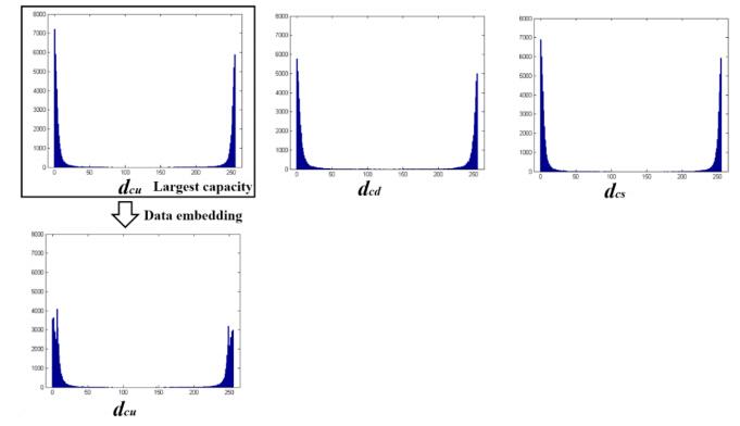
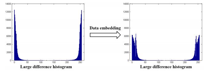
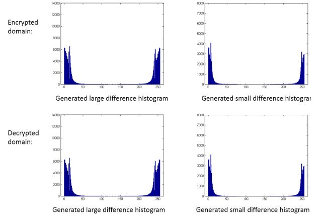
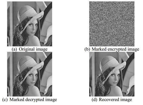
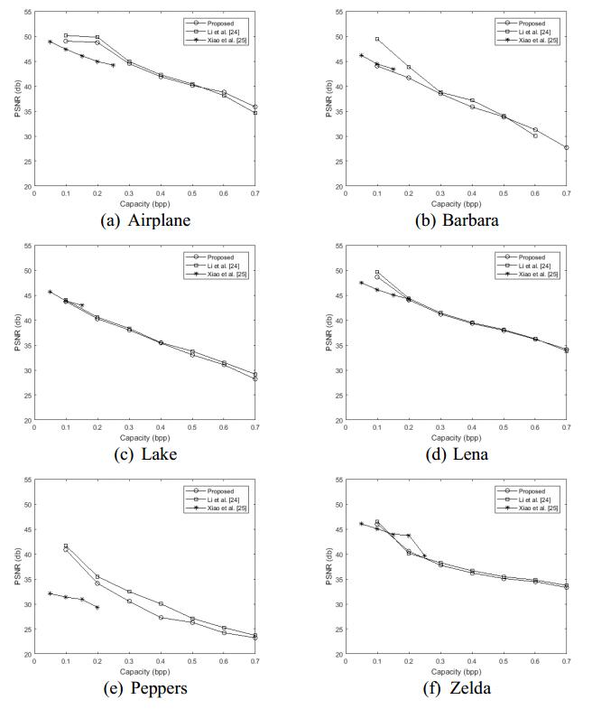
With the extensive use of cloud services in different applications, it's a problem for the cloud service provider to manage or process the privacy data that are encrypted by the content owner. Therefore, signal processing technology in the encrypted domain has attracted the attention of researchers. In this paper, we propose a new reversible data hiding method for encrypted images based on two-phase histogram shifting. In the proposed method, the original image is encrypted by using special image division and additive homomorphic encryption. After image encryption, the encrypted image can partially maintain spatial correlation for data embedding while the content security of the encrypted image is ensured. Due to the spatial correlation, the data hider can generate two difference histograms from the encrypted image, which provide high embedding capacity. A two-phase histogram shift scheme is used to embed the secret data into the two difference histograms. At the receiver side, the secret data can be extracted from the encrypted image or the decrypted image, and the image can be recovered to its original version without any error. The experimental results demonstrated that the proposed method can efficiently improve the capacity of data embedding and outperform other related methods, while the visual quality of the marked image can be maintained.
Citation: Kaimeng Chen, Chin-Chen Chang. High-capacity reversible data hiding in encrypted images based on two-phase histogram shifting[J]. Mathematical Biosciences and Engineering, 2019, 16(5): 3947-3964. doi: 10.3934/mbe.2019195
With the extensive use of cloud services in different applications, it's a problem for the cloud service provider to manage or process the privacy data that are encrypted by the content owner. Therefore, signal processing technology in the encrypted domain has attracted the attention of researchers. In this paper, we propose a new reversible data hiding method for encrypted images based on two-phase histogram shifting. In the proposed method, the original image is encrypted by using special image division and additive homomorphic encryption. After image encryption, the encrypted image can partially maintain spatial correlation for data embedding while the content security of the encrypted image is ensured. Due to the spatial correlation, the data hider can generate two difference histograms from the encrypted image, which provide high embedding capacity. A two-phase histogram shift scheme is used to embed the secret data into the two difference histograms. At the receiver side, the secret data can be extracted from the encrypted image or the decrypted image, and the image can be recovered to its original version without any error. The experimental results demonstrated that the proposed method can efficiently improve the capacity of data embedding and outperform other related methods, while the visual quality of the marked image can be maintained.

| [1] | C. Qin, X. Chen, X. Luo, et al., Perceptual image hashing via dual-cross pattern encoding and salient structure detection, Inform. Sci., 423 (2018), 284–302. |
| [2] | C. Qin, C. C. Chang and Y. P. Chiu, A novel joint data-hiding and compression scheme based on SMVQ and image inpainting, IEEE Trans. Image Process., 23 (2014), 969–978. |
| [3] | C. Qin, P. Ji, X. Zhang, et al., Fragile image watermarking with pixel-wise recovery based on overlapping embedding strategy, Signal Process., 138 (2017), 280–293. |
| [4] | Z. Qian, H. Xu, X. Luo, et al., New framework of reversible data hiding in encrypted JPEG bitstreams, IEEE Trans. Circuits Syst. Video Technol., 29 (2018), 351–362. |
| [5] | J. Tian, Reversible data embedding using a difference expansion, IEEE Trans. Circuits Syst. Video Technol., 13 (2003), 890–896. |
| [6] | Y. Hu, H. K. Lee and J. Li, DE-based reversible data hiding with improved overflow location map, IEEE Trans. Circuits Syst. Video Technol., 19 (2009), 250–260. |
| [7] | Y. Qiu, Z. Qian and L. Yu, Adaptive reversible data hiding by extending the generalized integer transformation, IEEE Signal Process. Lett., 23 (2016), 130–134. |
| [8] | Z. Ni, Y. Q. Shi, N. Ansari, et al., Reversible data hiding, IEEE Trans. Circuits Syst. Video Technol., 16 (2006), 354–362. |
| [9] | T. S. Nguyen, C. C. Chang and N. T. Huynh, A novel reversible data hiding scheme based on difference-histogram modification and optimal EMD algorithm, J. Vis. Commun. Image Represent., 33 (2015), 389–397. |
| [10] | J. Wang, J. Ni, X. Zhang, et al., Rate and distortion optimization for reversible data hiding using multiple histogram shifting, IEEE Trans. Cybern., 47 (2016), 315–326. |
| [11] | X. Li, J. Li, B. Li, et al., High-fidelity reversible data hiding scheme based on pixel-value-ordering and prediction-error expansion, Signal Process., 93 (2013), 198–205. |
| [12] | X. Qu and H. J. Kim, Pixel-based pixel value ordering predictor for high-fidelity reversible data hiding, Signal Process., 111 (2015), 249–260. |
| [13] | B. Ou, X. Li and J. Wang, High-fidelity reversible data hiding based on pixel-value-ordering and pairwise prediction-error expansion, J. Vis. Commun. Image Represent., 39 (2016), 12–23. |
| [14] | X. Zhang, Reversible data hiding in encrypted images, IEEE Signal Process. Lett., 18 (2011), 255–258. |
| [15] | W. Hong, T. Chen and H. Wu, An improved reversible data hiding in encrypted images using side match, IEEE Signal Process. Lett., 19 (2012), 199–202. |
| [16] | X. Liao and C. Shu, Reversible data hiding in encrypted images based on absolute mean difference of multiple neighboring pixels, J. Vis. Commun. Image Represent., 28 (2015), 21–27. |
| [17] | C. Qin and X. Zhang, Effective reversible data hiding in encrypted image with privacy protection for image content, J. Vis. Commun. Image Represent., 31 (2015), 154–164. |
| [18] | X. Wu and W. Sun, High-capacity reversible data hiding in encrypted images by prediction error, Signal Process., 104 (2014), 387–400. |
| [19] | X. Zhang, Separable reversible data hiding in encrypted image, IEEE Trans. Inf. Forensics Security, 7 (2012), 826–832. |
| [20] | C. Qin, W. Zhang, F. Cao, et al., Separable reversible data hiding in encrypted images via adaptive embedding strategy with block selection, Signal Process., 153 (2018), 109–122. |
| [21] | C. Qin, Z. He, X. Luo and J. Dong, Reversible data hiding in encrypted image with separable capability and high embedding capacity, Inform. Sci., 465 (2018), 285–304. |
| [22] | X. Zhang, Z. Qian, G. Feng, et al., Efficient reversible data hiding in encrypted images, J. Vis. Commun. Image Represent., 25 (2014), 322–328. |
| [23] | Z. Qian and X. Zhang, Reversible data hiding in encrypted image with distributed source encoding, IEEE Trans. Circuits Syst. Video Technol., 26 (2016), 636–646. |
| [24] | M. Li, D. Xiao, Y. Zhang, et al., Reversible data hiding in encrypted images using cross division and additive homomorphism, Signal Process.: Image Commun., 39 (2015), 234–248. |
| [25] | D. Xiao, Y. Xiang, H. Zheng, et al., Separable reversible data hiding in encrypted image based on pixel value ordering and additive homomorphism, J. Vis. Commun. Image Represent., 45 (2017), 1–10. |
| [26] | S. Yi, Y. Zhou and Z. Hua, Reversible data hiding in encrypted images using adaptive block-level prediction-error expansion, Signal Process.: Image Commun., 64 (2018), 78–88. |
| [27] | R. L. Rivest, L. Adleman and M. L. Dertouzos, On data banks and privacy homomorphisms, Found. Secure Comput., 4 (1978), 169–180. |
Figures(10) / Tables(2)

Kaimeng Chen, Chin-Chen Chang. High-capacity reversible data hiding in encrypted images based on two-phase histogram shifting[J]. Mathematical Biosciences and Engineering, 2019, 16(5): 3947-3964. doi: 10.3934/mbe.2019195


 DownLoad: