


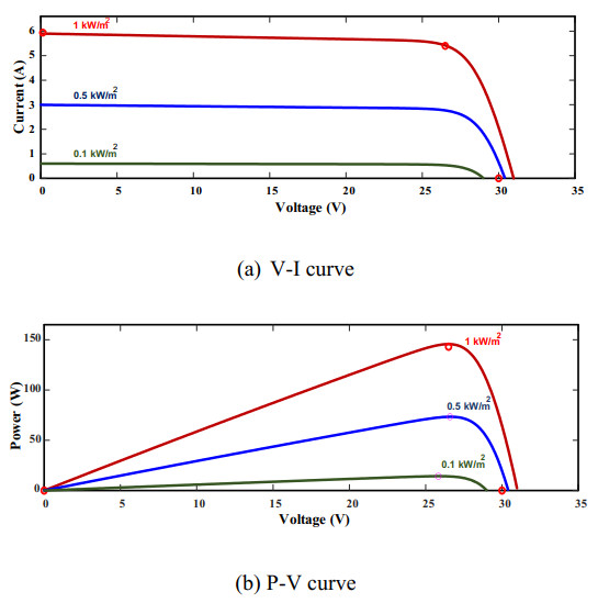
Figure 1.
PV panel characteristics: (a) V-I curve; (b) P-V curve.
Li-ion batteries can be charged with different techniques according to the charging time and required capacity usage. Most charging techniques face difficulties when implemented in PV systems due to the intermittent and unpredictable nature of the power supply. This paper addresses the issue of determining the appropriate charging technique for Li-ion batteries in a PV system. We have developed a mode-selective control approach that determines the optimal charging mode according to the given SOC and solar irradiation, aiming to maximize the utilization of the generated PV power. The developed control approach has been implemented using a dual-switched buck converter in the MATLAB/Simulink environment. The key control algorithm focused on regulating current, with different references being used based on the selected charging mode. Three references for charging current were set: the maximum current, the required current assigned based on the given SOC, and the pulsed current. The pulsed current reference was employed during a stage of the charging process to accelerate charging and prevent dissipation of PV power. Furthermore, a gain-scheduled controller with carefully picked control parameters was used to ensure stable operation across different modes. The results proved the effectiveness of the proposed control in reducing charging time and minimizing PV power dissipation without resorting to the use of harmful charging currents.
Citation: Rasool M. Imran, Kadhim Hamzah Chalok. Innovative mode selective control and parameterization for charging Li-ion batteries in a PV system[J]. AIMS Energy, 2024, 12(4): 822-839. doi: 10.3934/energy.2024039
| [1] | Imam Abadi, Chairul Imron, Mohammad Musa Bachrowi, Dwi Nur Fitriyanah . Design and implementation of battery charging system on solar tracker based stand alone PV using fuzzy modified particle swarm optimization. AIMS Energy, 2020, 8(1): 142-155. doi: 10.3934/energy.2020.1.142 |
| [2] | A.M.S.M.H.S.Attanayaka, J.P.Karunadasa, K.T.M.U.Hemapala . Estimation of state of charge for lithium-ion batteries - A Review. AIMS Energy, 2019, 7(2): 186-210. doi: 10.3934/energy.2019.2.186 |
| [3] | Mark P. McHenry, P. V. Brady, M. M. Hightower . PV-Li-ion-micropump membrane systems for portable personal desalination. AIMS Energy, 2016, 4(3): 444-460. doi: 10.3934/energy.2016.3.444 |
| [4] | Junguang Sun, Xiaodong Zhang, Wenrui Cao, Lili Bo, Changhai Liu, Bin Wang . State of health estimation of lithium-ion batteries based on data-driven methods with a selected charging voltage interval. AIMS Energy, 2025, 13(2): 290-308. doi: 10.3934/energy.2025012 |
| [5] | Saad Jarid, Manohar Das . An Electro-Thermal Model based fast optimal charging strategy for Li-ion batteries. AIMS Energy, 2021, 9(5): 915-933. doi: 10.3934/energy.2021043 |
| [6] | K. M. S. Y. Konara, M. L. Kolhe, Arvind Sharma . Power dispatching techniques as a finite state machine for a standalone photovoltaic system with a hybrid energy storage. AIMS Energy, 2020, 8(2): 214-230. doi: 10.3934/energy.2020.2.214 |
| [7] | Mansoor Soomro, Zeeshan Ali Shaikh, Mazhar Baloch, Abdul Manan Shaikh, Sohaib Tahir Chauhdary . Development of wind and solar systems for power charging: An application of an electric vehicle to grid systems. AIMS Energy, 2024, 12(3): 664-685. doi: 10.3934/energy.2024031 |
| [8] | Chi Van Nguyen, Thuy Nguyen Vinh . Design of energy balancing circuit for battery cells connected in series based on modifying the bidirectional CuK converter. AIMS Energy, 2022, 10(2): 219-235. doi: 10.3934/energy.2022012 |
| [9] | Nadwan Majeed Ali, Handri Ammari . Design of a hybrid wind-solar street lighting system to power LED lights on highway poles. AIMS Energy, 2022, 10(2): 177-190. doi: 10.3934/energy.2022010 |
| [10] | Anbazhagan Geetha, S. Usha, J. Santhakumar, Surender Reddy Salkuti . Forecasting of energy consumption rate and battery stress under real-world traffic conditions using ANN model with different learning algorithms. AIMS Energy, 2025, 13(1): 125-146. doi: 10.3934/energy.2025005 |
Li-ion batteries can be charged with different techniques according to the charging time and required capacity usage. Most charging techniques face difficulties when implemented in PV systems due to the intermittent and unpredictable nature of the power supply. This paper addresses the issue of determining the appropriate charging technique for Li-ion batteries in a PV system. We have developed a mode-selective control approach that determines the optimal charging mode according to the given SOC and solar irradiation, aiming to maximize the utilization of the generated PV power. The developed control approach has been implemented using a dual-switched buck converter in the MATLAB/Simulink environment. The key control algorithm focused on regulating current, with different references being used based on the selected charging mode. Three references for charging current were set: the maximum current, the required current assigned based on the given SOC, and the pulsed current. The pulsed current reference was employed during a stage of the charging process to accelerate charging and prevent dissipation of PV power. Furthermore, a gain-scheduled controller with carefully picked control parameters was used to ensure stable operation across different modes. The results proved the effectiveness of the proposed control in reducing charging time and minimizing PV power dissipation without resorting to the use of harmful charging currents.
Renewable energy sources (RESs) represent the future of electricity production. Solar energy is a potential choice among RESs that can meet the requirements of global energy demand because it is inexhaustible, clean, and available worldwide [1]. Photovoltaic (PV) energy is a form of solar energy that converts solar radiation into electricity through the use of power-electronic devices. Alongside its numerous benefits, PV energy exhibits some weaknesses such as intermittency, unpredictability, and lack of controllability. Algorithms to address one or more of the mentioned weaknesses are being developed by researchers [2,3,4]. Maximum power point tracking (MPPT) is an example of such algorithms, which aims to continuously track the instantaneous PV power and instruct the interfaced converter to maximize power output by adjusting either voltage or current [5]. The MPPT algorithm comes with several basic categories, such as incremental conductance, hill climbing, perturb and observe (P&O), fractional open-circuit voltage, fractional short-circuit current, and the look-up table method [6,7,8]. Modifications to the basic MPPT algorithm have also been developed based on fuzzy logic control, practical swarm optimization, artificial bee colonies, and artificial neural networks [9,10,11]. The maximum power generated while using the MPPT algorithm may exceed the demand load and thus the surplus may be wasted if not stored. To store the extra power generated in a PV system, energy storage systems (ESSs), e.g., batteries, can be utilized [12]. Li-ion batteries are frequently used in modern systems due to their efficient properties [13]. Despite its effectiveness, the Li-ion battery can be considered a costly solution and therefore requires special control to extend its life. Adjusting the charging current via a typical battery management system (BMS) ensures a safe charging current that helps it achieve its longest possible lifespan. Most BMSs are configured to obtain the desired power from controllable sources to meet the necessary charging requirements. In the case of the PV system, the input power is uncontrollable, requiring additional modification of the BMS algorithm to perform its task. Relevant modifications made to PV-ESS systems connected to the electricity grid are presented in [14,15,16]. Primarily, grid-connected PV systems feed the surplus generated-power into the grid most of the time. Also, using the maximum capacity of the battery is not crucial in such systems because the battery may perform the required purpose even at half its capacity. The task becomes more difficult in autonomous PV-battery systems, where there is a trade-off between absorbing maximum power and maintaining an adequate charging current for the battery. A strategy for obtaining the maximum possible power generated by the PV panel while regulating the charging voltage of the battery in a standalone PV-battery system is introduced by [17,18]. This strategy utilizes two DC-DC converters: the first is configured to achieve maximum power using the MPPT algorithm, while the second is dedicated to battery charging control. The strategy uses a conventional charging technique that supplies the battery with an appropriate charging voltage. However, the issue of PV power dissipation may not be properly addressed in this strategy. Also, the high complexity of the system using two DC-DC converters presents a design challenge. Another two-stage topology for tracking the maximum PV power and regulating the battery voltage is presented in [19]. The topology considers the use of fuzzy logic-based MPPT to obtain the maximum power under different irradiations while maintaining the charging voltage. The presented topology simplifies the overall design, and the MPPT used ensures minimal ripples in the regulated voltage. However, this topology is solely focused on controlling the battery voltage, without regulating the battery current, which may lead to battery damage due to high charging currents. The current-based MPPT technique is a solution that attains the maximum power by introducing limited perturbations into the demand current [20,21]. This technique is applied via a single DC-DC converter to obtain maximum PV power on one hand and extend battery life by avoiding overcharge on the other hand. Mode-selective control is another solution that incorporates the benefit of the MPPT algorithm while regulating the voltage at the battery terminals [22,23]. Mode-selective control chooses between the MPPT algorithm and constant voltage charging depending on certain information, such as the available PV power, load demand, and SOC [24]. The existing mode-selective control does not take into account altering the charging method, so the constant-voltage charging method is typically used. Altering the charging method at a certain stage of the charging scenario can be implemented to make the battery absorb more power. This paper presents a modification to mode-selective control that enables it to choose between current-dependent MPPT and constant-voltage charging for Li-ion batteries. The modification lies in the use of a pulsed-current charging method instead of the constant-voltage method when the PV power exceeds the required power determined based on the battery SOC and attached load. The pulsed-current charging method provides rest intervals between high-current pulses to prevent overheating of the battery and ensure safe operation [25]. Modifications are necessary for both voltage and current controllers to ensure their reliability when different control references are used. Moreover, a gain-scheduled strategy is implemented for the current controller to adjust control parameters following the change in charging mode (pulsed-current and constant-voltage). The contributions of this paper can be summarized in the following points:
● Utilize a current-dependent MPPT algorithm to charge Li-ion batteries through mode-selective control while considering battery health constraints.
● Introduce the pulsed-current charging approach at a stage of the charging process to speed up charging and reduce the dissipation of PV power.
● Employ a gain-scheduled strategy that adapts controller parameters according to the required charging mode to enhance system stability.
This paper includes five sections after the introduction. Section 2 presents the design of the system used and its main components. Section 3 describes in detail the essential control techniques employed in this study. Section 4 defines the main parameters of the proposed control and verifies their stability through system roots analysis. Section 5 outlines the case study scenarios and presents their associated results. Section 6 provides the conclusion of the paper.
The utilized system consists of three main components: A PV panel, a DC-DC converter, and a Li-ion battery pack, as will be illustrated in this section. A PV panel is a collection of PV cells connected in parallel and series to provide the required voltage and current. A 150 W monocrystalline PV panel of 30 cells and 25 V at the maximum power is utilized. Each PV cell on the panel can be presented as a P-N junction diode that converts the light applied to it into electric charge. The relationship between the load current and cell voltage can be represented by [26]:
| I=IL−IS[exp(V+IRSv)−1] | (1) |
where I, IL, and IS represent the load current, insolation light current, and saturation current, respectively. The insolation light current, or light-generated current, can be defined as the current generated by the sun's irradiance falling on the PV cell. V, v, and RS represent the output voltage, timing completion factor, and resistance of series-connected cells, respectively. The V-I and P-V curves of the utilized PV panel under different irradiance levels are shown in Figure 1.
The DC-DC converter is a power electronics-based device that steps up or steps down input voltage with the help of an inductor and capacitor. In the utilized system, the voltage of the PV panel is always higher than the load voltage. Therefore, a step-down (buck) converter is used. A buck converter can be formed in different types with one or two switches. Since both output voltage and current need to be controlled, a dual-switch buck converter is utilized, as shown in Figure 2.
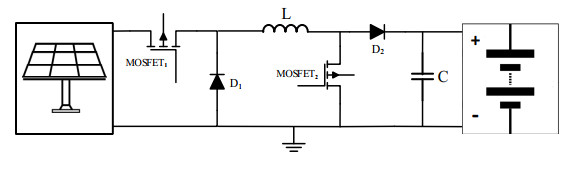
Each switch in the buck converter is responsible for regulating a specific component (voltage or current). Both switches are MOSFETs, chosen to meet the requirements for rated voltage, current, and switching frequency. The values of the buck inductor (L) and capacitor (C) can be found by [27]:
| L=[VO(Vin−VO)fSIrVin];C=[Ir8fSVr] | (2) |
where VO, Vin, Ir, fS, and Vr are the output voltage, input voltage, ripple current, chopping frequency, and ripple voltage, respectively.
The Li-ion battery pack is a set of Li-ion cells connected in parallel and series to produce the desired voltage and current. An NCR18650B Li-ion pack of four cells connected in series with 14 V and 4 Ah capacity is used. The most widely used RC model of the Li-ion cell can be represented in Figure 3. R0, R1, and C1 in Figure 3 represent the internal resistance, hysteresis resistance, and hysteresis capacitance, respectively.
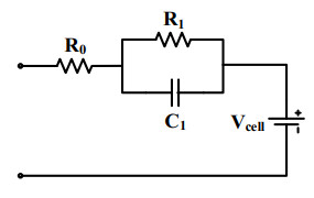
When modelling the battery cell, battery parameters (R0, R1, and C1) are represented as 2D lookup tables. The x-axis and y-axis of the lookup tables correspond to the SOC and temperature, respectively. These battery parameters are established through a parametrization process that is repeated several times for various temperatures. The parameterization process involves experimentally discharging a fully charged battery at each particular temperature and observing the battery voltage for each SOC value specified in the lookup tables. A single voltage-SOC curve is plotted for each temperature, and the resulting curves are used in the Simulink design optimization tool in MATLAB to establish breakpoints for the 2D lookup tables of the battery parameters. The battery output voltage can be denoted as a non-linear function of the SOC.
The utilized system comprises several stages of control. The essential control algorithms along with the proposed control approach are presented in this section.
The MPPT in a PV system is an algorithm that continually attempts to attain the maximum power (PMax) produced by the PV panel and inject it into the load through a power electronic converter. Hill climbing and P&O are more common and straightforward compared to other MPPT algorithms. The hill climbing algorithm creates a perturbation in the duty ratio of a power-electronic converter whereas the P&O algorithm introduces a disturbance in the operating voltage of the PV panel. The P&O algorithm is known for its well-regulated output voltage and fast response compared to the hill climbing algorithm [28]. The P&O algorithm operates under the assumption that if a slight change in PV voltage results in an increase in power drawn from the PV panel, this means that the operating point is moving toward the PMax. Conversely, if the voltage change causes a decrease in power drawn, the operating point is moving away from the PMax. This process is repeated in the direction that increases power until PMax is reached, as:
| PPV=VI | (3) |
| Vnew={V+mΔVforPPV>PPVoldV−mΔVforPPV<PPVold | (4) |
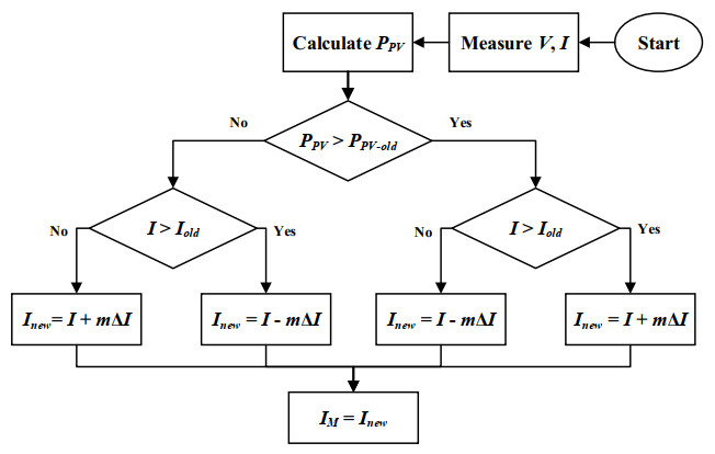
where Vnew, m, ΔV, PPV, and PPV-old represent the new iteration voltage, accelerating gain, voltage perturbation, recent PV power, and the PV power of the previous iteration, respectively [29]. The conventional P&O algorithm can be adapted to track current perturbation (ΔI) instead of voltage perturbation, as described in [30]. In this way, if both the power and current values for the recent iteration are greater or less than those of the previous iteration, the new current value is attained by adding ΔI, otherwise, it can be attained by subtracting ΔI. The process of generating the maximum current based on the current perturbation is illustrated in the flowchart depicted in Figure 4. This modification to the P&O algorithm makes it more convenient when used in current control systems, such as the case in this paper.
Techniques for charging Li-ion batteries vary in complexity depending on system significance. The constant voltage charging technique is the simplest approach, as most adapters provide a fixed voltage and demand-based variable current. More sophisticated approaches can be used to offer other purposes, e.g., constant current-constant voltage, which is often used in present-day applications. Moreover, when fast charging is needed, techniques like pulsed-current and pulsed-voltage can be employed. The pulsed-current method is particularly suitable for systems where the main control signal is the charging current. This technique provides the battery with intermittent high current and periodic rest intervals in between, which ensures retrieving the battery to its normal state and floating voltage. The rest interval can also enlarge the energy density of the battery, enabling it to accept the upcoming high current pulse. The length of the rest interval can be fixed or variable depending on control requirements of the charging technique. Current pulses are characterized by parameters such as amplitude (Ipeak), duty cycle (Dp), and frequency (fp). These parameters are tuned to ensure fast charging and safe operating temperature. The frequency of pulsed current is defined below, where T, tp, and tr refer to the period, pulse width, and rest interval, respectively.
| fp=1T | (5) |
| T=tp+tr | (6) |
| Dp=tpT | (7) |
The average value (Iav) of the pulsed current can be obtained as:
| Iav=DpIpeak | (8) |
The control of the pulsed-current charging approach requires certain features such as fast response and overshoot damping, especially due to the sharp changes in the reference signal. Therefore, if PI control is used, the control parameters need careful tuning to make sure that the operation is stable.
The MPPT algorithm encounters some restrictions when applied to an autonomous system comprising a PV panel and Li-ion battery. In such systems, the current flowing into the battery must be restrained within certain limits to prolong battery life and maximize capacity utilization. The proposed technique aims, on one hand, to leverage the benefits of the MPPT algorithm so as to extract the maximum available PV power. On the other hand, it intends to limit the battery current to a safe margin determined based on the SOC. The maximum current (IM) obtained via the current-based MPPT algorithm is compared with the current required by the battery and attached load (Ir). Subsequently, the optimal current (Iopt) is set as follows:
| Iopt={IMforIM<IrIrforIM>Ir | (9) |
In the equation above, IM is determined through the current-based MPPT algorithm, and Ir refers to the total current required by the battery (Ir_b) and any attached load (IL). To achieve Ir_b, the Li-ion battery pack undergoes a full charging scenario with a constant voltage of 14.4 V. Accordingly, the current absorbed by the battery varies from 2 to 0.4 C as the SOC moved from 0% to 100%. The current and SOC data are organized on the two axes of a 2D lookup table. Thereafter, the Ir_b is derived based on the SOC information, as shown in Figure 5. Although the SOC can be estimated using various methods, the extended Kalman filter (EKF) presented in [31] was used.
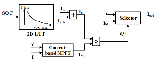
Whenever Ir is picked, any power between the maximum and required margins will be wasted. If the Li-ion battery is adopted to absorb more than Ir_b, the wasted power can be reduced. This can be achieved by delivering a higher current to the battery, such as through a pulsed-current charging approach. Hence, it is proposed that the mode-selective control switches to another selection, i.e., setting the pulsed-current as a reference when the IM exceeds 1.5 Ir. Charging with pulsed-current allows for accepting twice the rated current of the battery. The pulsed-current is set to be chopped with a duty cycle of 75% and a frequency of 0.03 Hz to maintain an acceptable rise in battery temperature [32]. To ensure safe charging, the amplitude of pulsed-current should not exceed twice the rated current of the battery.
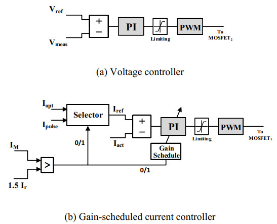
The firing angle of MOSFET2 is generated via a voltage controller as in Figure 6(a). The controller gains (Kp and Ki) were tuned by using a trial-and-error method and listed in Table 1. Similarly, the firing angles of MOSFET1 were produced by the current controller, which forms the main control in this paper. The gains of the current controller were initially obtained by a trial-and-error method. These gains enable the controller to work efficiently under two cases: when the constant voltage approach is picked and when the controller switches to the MPPT algorithm. When the control reference is set based on the pulsed-current charging approach, triggered when the maximum power exceeds 1.5 of the required power, overshoot happens at every pulse edge. Current overshoot may exceed the ratings of converter components and potentially damage the battery pack. To overcome this issue, different control gains are required in order to dampen oscillations when the pulsed-current approach is used. A gain scheduled control is suggested to be used for regulating battery current. This control changes its gains according to the selected current reference. Further trial-and-error tuning was conducted to determine new optimal values of Kp and Ki that exhibit damping properties when utilizing the pulsed-current method.
| Parameter | Value |
| Voltage proportional gain | 10.75 |
| Voltage integral gain | 0.85 |
| Opt. current proportional gain | 3.25 |
| Opt. current integral gain | 30.4 |
| Pulsed-current proportional gain | 22.8 |
| Pulsed-current integral gain | 83 |
 DownLoad:
CSV
DownLoad:
CSV
The newly obtained gains, along with the old ones, are set and ready to be used when needed for the gain-scheduled current controller (see Figure 6(b)). Vref, Vmeas, Iref, and Iact in Figure 6 represent the reference and measured values for voltage and current, respectively. The obtained current control parameters are also listed in Table 1 (initial values). These parameters must be verified in both mentioned cases to ensure stable operation. Assuming a steady voltage while deriving the dynamic states of the current controller, the only switch considered for converter configuration is the current-regulating switch, MOSFET1. The mathematical expressions for the dynamic states, inductor current (iL), and capacitor voltage (vC) can be derived by inspecting the average behavior of the converter when MOSFET1 is switched on and off, as detailed in Eqs (10) and (11). Eq (12) clarifies the system output, which represents the controlled battery current.
| diLdt=−vCL+VinDL | (10) |
| dvCdt=iLC−vCRTC | (11) |
| iO=iL−iC | (12) |
where D is the duty ratio for MOSFET1, and RT is the load resistance that refers to the typical internal resistance of the battery.
The equations for the dynamic states and system output are rewritten after performing the Laplace transform in Eqs (13–15).
| siL=−1LvC+VinLD | (13) |
| svC=1CiL−1RTCvC | (14) |
| iO(s)=iL−ωCvC | (15) |
Given that the input and output of the system are D and iO, respectively, the transfer function of the converter (GC (s)) can be expressed in (16) after implementing some mathematical arrangements.
| GC(s)=iO(s)D(s)=Vin(sCRT−ωCRT+1)s2LCRT+sL+RT | (16) |
The transfer function of the PI current controller is given in (17). Eq (18) defines the transfer function for the entire closed-loop system of the converter and current controller, which is depicted in Figure 7(a).
| GI(s)=KPs+Kis | (17) |
| GT(s)=iO(s)Iref(s)=GCGI1+GCGI | (18) |
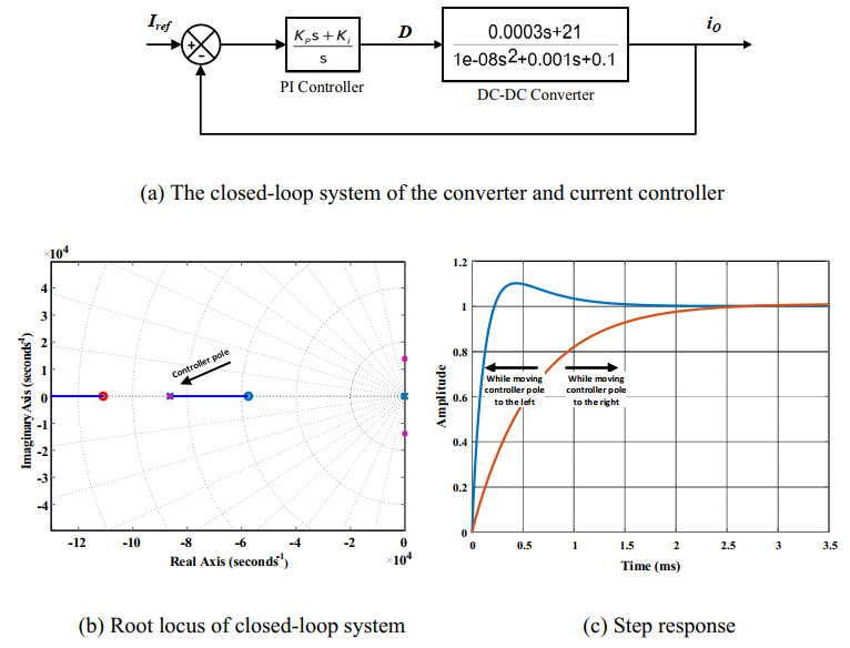
Using the control and system parameters from Tables 1 and 2, the root locus of the entire system can be plotted in Figure 7(b). The closed-loop system has two zeros and three poles, all of which lie within the left-half of the s-plane, which indicates system stability. The far pole on the left is related to the PI controller, and it primarily influences the step response characteristics. Figure 7(c) shows the closed-loop step response when moving the controller pole to the left, which speeds up the system response and makes it suitable for use with the current reference (Iopt). On the other hand, moving the controller pole to the right slows down the system response while reducing overshoot, making it more suitable for use with the current reference (Ipulse). This helps in selecting appropriate gains for the current controller in both mentioned cases.
| Parameter | Value |
| PV panel voltage | 30 V |
| PV panel rating power | 150 W |
| Li-ion battery pack voltage | 14 V |
| Li-ion battery pack capacity | 4000 mAh |
| Buck inductor | 680 µH |
| Buck capacitor | 100 µF |
| MOSFET1 / MOSFET2 | IRF740, 10 A |
DownLoad:
CSV
The proposed system has been applied in the Simulink environment of MATLAB R2023b using the system parameters from Table 2. Three different scenarios are suggested to verify the performance of the control approach, as follows:
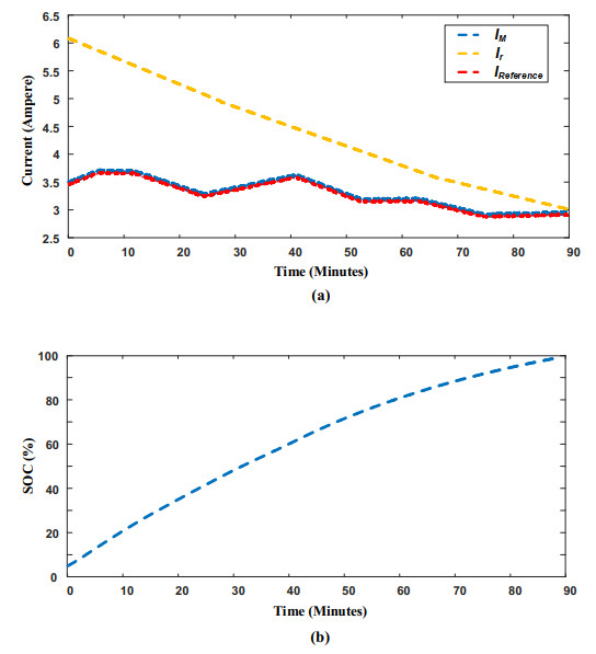
We are given that the required power by the battery at any instant is determined based on the corresponding SOC. Assuming there is no load current for the attached load, thus, the required current (Ir) is set to be equal to the required current by the battery (Ir_b), this scenario assumes low PV irradiation, in which for a charging cycle of the Li-ion battery, the PV panel consistently produces output power lower than the required power. Figure 8(a) illustrates this scenario in terms of currents (Ir and IM). Figure 8(b) shows the progress of SOC verses time in minutes. Note that the battery required ninety minutes to reach full charge, which is the longest duration among the other scenarios considered. The mode-selective control selects IM as the reference current. This scenario has experienced no power losses and all PV-produced power has been transferred to the battery.
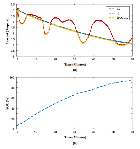
This scenario assumes that PV power varies, rising above the required power at certain times and falling below it at other times during the charging process. This scenario is more realistic as it emulates irradiation variances in semi-cloudy weather.
The controller in this case ensures smooth swapping of the current reference between the IM and Ir. The selected reference current is depicted in Figure 9(a) in yellow. As shown in Figure 9(b), the SOC progression accelerated, and the time to reach a fully charged state has reduced because the battery charging current reached its required value most of the time. Note from Figure 9(a) that there is no significant overshoot during transitions between IM and Ir. Therefore, the PI gains used in the current controller are doable for both current references. It is also noteworthy that IM did not exceed 1.5 Ir, thus the pulsed-current approach was not activated.
In this scenario, the controller experiences all possible current references within one charging cycle, as shown in Figure 10(a). During the interval of 1–3 minutes, IM was picked as the reference because the maximum PV power was lower than the required power. In the subsequent interval (3–12.5 min), IM exceeds Ir but remains below the margin of 1.5 Ir. The controller in this interval picked Ir to avoid excessive charging current and maintain a healthy charging process. In the interval of 22–27 minutes, IM became greater than 1.5 Ir, prompting the controller to initiate charging with pulsed-current.
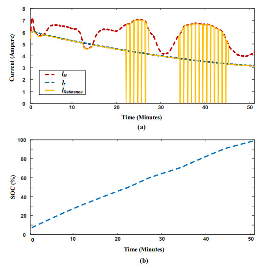
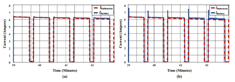
Note that the controller effectively tracked the pulsed-current reference even during rapid changes. This verifies the effectiveness of gain-scheduled control in selecting the appropriate gains for the given situation. At the same time, damping properties of the selected gains mitigated overshoot without compromising steady state operation speed. Figure 10(b) illustrates that SOC progression is the fastest among the scenarios, achieved by speeding up charging using the pulsed-current method. Furthermore, charging via pulsed-current increased energy transfer to the battery by 20% under the given irradiation conditions. This demonstrates the effectiveness of the control algorithm in conserving PV energy from dissipation. Figure 11 clarifies the response of actual current following changes in its reference during pulsed-current charging, comparing cases with and without gain-scheduled control. The selected gains noticeably reduced overshoot for this particular case. Figure 11 also shows that the transition between control gains is smooth and does not compromise stability.
This paper developed a mode-selective current control for Li-ion battery charging in a PV system. The developed control aimed to leverage the MPPT algorithm to optimize PV power utilization, while simultaneously ensuring the battery current remains within a safe margin. Furthermore, a pulsed-current charging approach was employed to minimize power dissipation and efficiently grasp excess PV power in a safe manner. The current controller was designed to handle three forms of references: maximum, required, and pulsed. A gain-scheduled controller was suggested that adjusts its parameters following the selected current reference. The developed controller has undergone various trial-and-error scenarios to assign the optimal gains. These gains have also been verified for stable operation through root locus analysis of the closed-loop system. The developed controller was tested in the MATLAB/Simulink environment for various expected scenarios to verify its effectiveness. The results reveal that the proposed control efficiently converts most of the available PV power into the Li-ion battery while taking into account battery health constraints and minimizing power dissipation. The results also demonstrate stable operation of the developed controller under different scenarios.
The authors declare they have not used Artificial Intelligence (AI) tools in the creation of this article.
The paper was a collaborative effort between both authors. Rasool M. Imran contributed to the methodology, conducted the theoretical analysis, and wrote the original draft of the manuscript. Kadhim Hamzah Chalok verified the findings through simulation and edited the manuscript. All authors have read and approved the final version of the manuscript.
The authors declare no conflicts of interest.
| [1] |
Morsy N, Gaber M, Chaves-Ávila JP, et al. (2022) Automatic generation control of a future multisource power system considering high renewables penetration and electric vehicles: Egyptian power system in 2035. IEEE Access 10: 51662‒51681. https://doi.org/10.1109/ACCESS.2022.3174080 doi: 10.1109/ACCESS.2022.3174080

|
| [2] |
Sarvi M, Azadian A (2022) A comprehensive review and classified comparison of MPPT algorithms in PV systems. Energy Syst 13: 281‒320. https://doi.org/10.1007/s12667-021-00427-x doi: 10.1007/s12667-021-00427-x
|
| [3] |
Katche ML, Makokha AB, Zachary SO, et al. (2023) A comprehensive review of maximum power point tracking (MPPT) techniques used in solar PV systems. Energies 16: 2206. https://doi.org/10.3390/en16052206 doi: 10.3390/en16052206
|
| [4] |
Li C, Zhu CX, Zhang N, et al. (2022) Free vibration of self-powered nanoribbons subjected to thermal-mechanical-electrical fields based on a nonlocal strain gradient theory. Appl Math Model 110: 583‒602. https://doi.org/10.1016/j.apm.2022.05.044 doi: 10.1016/j.apm.2022.05.044
|
| [5] |
Ni J, Xiang J (2023) A concise control method based on spatial-domain dp/dv calculation for MPPT/power reserved of PV systems. IEEE Trans Energy Convers 38: 3‒14. https://doi.org/10.1109/TEC.2022.3195565 doi: 10.1109/TEC.2022.3195565
|
| [6] |
Jately V, Azzopardi B, Joshi J, et al. (2021) Experimental analysis of hill-climbing MPPT algorithms under low irradiance levels. Renewable Sustainable Energy Rev 150: 111467. https://doi.org/10.1016/j.rser.2021.111467 doi: 10.1016/j.rser.2021.111467
|
| [7] |
Ali AIM, Mohamed HRA (2022) Improved P&O MPPT algorithm with efficient open-circuit voltage estimation for two-stage grid-integrated PV system under realistic solar radiation. Int J Electr Power Energy Syst 137: 107805. https://doi.org/10.1016/j.ijepes.2021.107805 doi: 10.1016/j.ijepes.2021.107805
|
| [8] |
Hassan A, Bass O, Masoum MA (2023) An improved genetic algorithm based fractional open circuit voltage MPPT for solar PV systems. Energy Rep 9: 1535‒1548. https://doi.org/10.1016/j.egyr.2022.12.088 doi: 10.1016/j.egyr.2022.12.088
|
| [9] |
Fayrouz D (2023) Improved MPPT algorithm: Artificial neural network trained by an enhanced Gauss-Newton method. AIMS Electron Electr Eng 7: 380‒405. https://dx.doi.org/10.3934/electreng.2023020 doi: 10.3934/electreng.2023020
|
| [10] |
Sangrody R, Taheri S, Cretu AM, et al. (2023) An improved PSO-based MPPT technique using stability and steady state analyses under partial shading conditions. IEEE Trans Sustainable Energy 15: 136‒145. https://doi.org/10.1109/TSTE.2023.3274939 doi: 10.1109/TSTE.2023.3274939
|
| [11] |
Aly M, Rezk H (2022) An improved fuzzy logic control-based MPPT method to enhance the performance of PEM fuel cell system. Neural Comput Appl 34: 4555‒4566. https://doi.org/10.1007/s00521-021-06611-5 doi: 10.1007/s00521-021-06611-5
|
| [12] |
Yan HW, Farivar GG, Beniwal N, et al. (2023) Battery lifetime extension in a stand-alone microgrid with flexible power point tracking of photovoltaic system. IEEE J Emerg Sel Top Power Electron 11: 2281‒2290. https://doi.org/10.1109/JESTPE.2022.3212702 doi: 10.1109/JESTPE.2022.3212702
|
| [13] |
Yadav I, Sachan S, Maurya SK, et al. (2023) Effective battery charging system using step voltage and step duty size-based MPPT controller for solar PV system. Energy Rep 10: 744‒755. https://doi.org/10.1016/j.egyr.2023.07.033 doi: 10.1016/j.egyr.2023.07.033
|
| [14] |
Sorte PK, Panda KP, Panda G (2022) Current reference control based MPPT and investigation of power management algorithm for grid-tied solar PV-battery system. IEEE Syst J 16: 386‒396. https://doi.org/10.1109/JSYST.2021.3052959 doi: 10.1109/JSYST.2021.3052959
|
| [15] |
Chankaya M, Hussain I, Ahmad A, et al. (2021) Multi-objective grasshopper optimization based MPPT and VSC control of grid-tied PV-battery system. Electronics 10: 2770. https://doi.org/10.3390/electronics10222770 doi: 10.3390/electronics10222770
|
| [16] |
Jaga OP, GhatakChoudhuri S (2023) A smart control for self-reliant single-phase, grid-tied photovoltaic-battery storage system. Sustainable Energy Technol Assess 57: 103269. https://doi.org/10.1016/j.seta.2023.103269 doi: 10.1016/j.seta.2023.103269
|
| [17] |
Hasabelrasul H, Cai Z, Sun L, et al. (2022) Two-stage converter standalone PV-battery system based on VSG control. IEEE Access 10: 39825‒39832. https://doi.org/10.1109/ACCESS.2022.3165664 doi: 10.1109/ACCESS.2022.3165664
|
| [18] |
Yilmaz U, Kircay A, Borekci S (2018) PV system fuzzy logic MPPT method and PI control as a charge controller. Renewable Sustainable Energy Rev 81: 994‒1001. https://doi.org/10.1016/j.rser.2017.08.048 doi: 10.1016/j.rser.2017.08.048
|
| [19] |
Pathak PK, Yadav AK (2019) Design of battery charging circuit through intelligent MPPT using SPV system. Sol Energy 178: 79‒89. https://doi.org/10.1016/j.solener.2018.12.018 doi: 10.1016/j.solener.2018.12.018
|
| [20] |
Raiker GA, Loganathan U, Reddy SB (2021) Current control of boost converter for PV interface with momentum-based perturb and observe MPPT. IEEE Trans Ind Appl 57: 4071‒4079. https://doi.org/10.1109/TIA.2021.3081519 doi: 10.1109/TIA.2021.3081519
|
| [21] |
Arun S, Ahamed TI, Lakaparampil ZV, et al. (2022) An autonomous solar PV system using boost TPC for energy harvesting with mode-based power flow management control. Sustainable Energy Technol Assess 53: 102528. https://doi.org/10.1016/j.seta.2022.102528 doi: 10.1016/j.seta.2022.102528
|
| [22] |
Mahmood H, Blaabjerg F (2022) Autonomous power management of distributed energy storage systems in islanded microgrids. IEEE Trans Sustainable Energy 13: 1507‒1522. https://doi.org/10.1109/TSTE.2022.3156393 doi: 10.1109/TSTE.2022.3156393
|
| [23] |
Chtita S, Derouich A, El Ghzizal A, et al. (2021) An improved control strategy for charging solar batteries in off-grid photovoltaic systems. Sol Energy 220: 927‒941. https://doi.org/10.1016/j.solener.2021.04.003 doi: 10.1016/j.solener.2021.04.003
|
| [24] |
Traiki G, El Magri A, Lajouad R, et al. (2023) Multi-objective control and optimization of a stand-alone photovoltaic power conversion system with battery storage energy management. IFAC J Syst Control 26: 100227. https://doi.org/10.1016/j.ifacsc.2023.100227 doi: 10.1016/j.ifacsc.2023.100227
|
| [25] | Imran RM, Farhan BS, Yang YJ, et al. (2021) Comparative investigation of lithium-ion charging methods implemented via a single DC/DC converter. 5th International Conference on Green Energy and Applications (ICGEA), Singapore, 32‒37. https://doi.org/10.1109/ICGEA51694.2021.9487608 |
| [26] |
Viswa Teja A, Razia Sultana W, Salkuti SR (2023) Performance explorations of a PMS motor drive using an ANN-based MPPT controller for solar-battery powered electric vehicles. Designs 7: 79. https://doi.org/10.3390/designs7030079 doi: 10.3390/designs7030079
|
| [27] | Lee J (2015) Basic calculation of a buck converter's power stage. Richtek Technol Corp AN041: 1‒8. Available from: http://acots.info/pdf/an041_en.pdf. |
| [28] | Liu F, Kang Y, Zhang Y, et al. (2008) Comparison of P&O and hill climbing MPPT methods for grid-connected PV converter. 2008 3rd IEEE Conference on Industrial Electronics and Applications, Singapore, 804‒807. https://doi.org/10.1109/ICIEA.2008.4582626 |
| [29] | Mirbagheri SZ, Aldeen M, Saha S (2015) A comparative study of MPPT algorithms for standalone PV systems under RCIC. 2015 IEEE PES Asia-Pacific Power and Energy Engineering Conference (APPEEC), Brisbane, Australia, 1‒5. https://doi.org/10.1109/APPEEC.2015.7380869 |
| [30] | Mohapatra A, Nayak B, Mohanty KB (2014) Current based novel adaptive P&O MPPT algorithm for photovoltaic system considering sudden change in the irradiance. 2014 IEEE International Conference on Power Electronics, Drives and Energy Systems (PEDES), Mumbai, India, 1‒4. https://doi.org/10.1109/PEDES.2014.7042032 |
| [31] |
Imran RM, Li Q, Flaih FMF (2020) An enhanced lithium-ion battery model for estimating the state of charge and degraded capacity using an optimized extended kalman filter. IEEE Access 8: 208322‒208336. https://doi.org/10.1109/ACCESS.2020.3038477 doi: 10.1109/ACCESS.2020.3038477
|
| [32] |
Huang X, Li Y, Acharya AB, et al. (2020) A review of pulsed current technique for lithium-ion batteries. Energies 13: 2458. https://doi.org/10.3390/en13102458 doi: 10.3390/en13102458
|
| 1. | Rasool M. Imran, Kadhim Hamzah Chalok, Siraj A. M. Nasrallah, Innovative two-stage thermal control of DC-DC converter for hybrid PV-battery system, 2025, 9, 2578-1588, 26, 10.3934/electreng.2025002 |
Figures(11) / Tables(2)

Rasool M. Imran, Kadhim Hamzah Chalok. Innovative mode selective control and parameterization for charging Li-ion batteries in a PV system[J]. AIMS Energy, 2024, 12(4): 822-839. doi: 10.3934/energy.2024039

| Parameter | Value |
| Voltage proportional gain | 10.75 |
| Voltage integral gain | 0.85 |
| Opt. current proportional gain | 3.25 |
| Opt. current integral gain | 30.4 |
| Pulsed-current proportional gain | 22.8 |
| Pulsed-current integral gain | 83 |
DownLoad:
CSV
| Parameter | Value |
| PV panel voltage | 30 V |
| PV panel rating power | 150 W |
| Li-ion battery pack voltage | 14 V |
| Li-ion battery pack capacity | 4000 mAh |
| Buck inductor | 680 µH |
| Buck capacitor | 100 µF |
| MOSFET1 / MOSFET2 | IRF740, 10 A |
DownLoad:
CSV
| Parameter | Value |
| Voltage proportional gain | 10.75 |
| Voltage integral gain | 0.85 |
| Opt. current proportional gain | 3.25 |
| Opt. current integral gain | 30.4 |
| Pulsed-current proportional gain | 22.8 |
| Pulsed-current integral gain | 83 |
| Parameter | Value |
| PV panel voltage | 30 V |
| PV panel rating power | 150 W |
| Li-ion battery pack voltage | 14 V |
| Li-ion battery pack capacity | 4000 mAh |
| Buck inductor | 680 µH |
| Buck capacitor | 100 µF |
| MOSFET1 / MOSFET2 | IRF740, 10 A |
