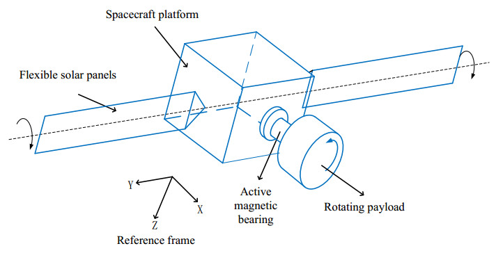
This study focuses on the attitude control of a flexible spacecraft comprising rotating appendages, magnetic bearings, and a satellite platform capable of carrying flexible solar panels. The kinematic and dynamic models of the spacecraft were established using Lagrange methods to describe the translation and rotation of the spacecraft system and its connected components. A simplified model of the dynamics of a five-degrees-of-freedom (DOF) active magnetic bearing was developed using the equivalent stiffness and damping methods based on the magnetic gap variations in the magnetic bearing. Next, a fixed-time sliding mode control method was proposed for each component of the spacecraft to adjust the magnetic gap of the active magnetic bearing, realize a stable rotation of the flexible solar panels, obtain a high inertia for the appendage of the spacecraft, and accurately control the attitude. Finally, the numerical simulation results of the proposed fixed-time control method were compared with those of the proportional-derivative control method to demonstrate the superiority and effectiveness of the proposed control law.
Citation: Gaowang Zhang, Feng Wang, Jian Chen, Huayi Li. Fixed-time sliding mode attitude control of a flexible spacecraft with rotating appendages connected by magnetic bearing[J]. Mathematical Biosciences and Engineering, 2022, 19(3): 2286-2309. doi: 10.3934/mbe.2022106
This study focuses on the attitude control of a flexible spacecraft comprising rotating appendages, magnetic bearings, and a satellite platform capable of carrying flexible solar panels. The kinematic and dynamic models of the spacecraft were established using Lagrange methods to describe the translation and rotation of the spacecraft system and its connected components. A simplified model of the dynamics of a five-degrees-of-freedom (DOF) active magnetic bearing was developed using the equivalent stiffness and damping methods based on the magnetic gap variations in the magnetic bearing. Next, a fixed-time sliding mode control method was proposed for each component of the spacecraft to adjust the magnetic gap of the active magnetic bearing, realize a stable rotation of the flexible solar panels, obtain a high inertia for the appendage of the spacecraft, and accurately control the attitude. Finally, the numerical simulation results of the proposed fixed-time control method were compared with those of the proportional-derivative control method to demonstrate the superiority and effectiveness of the proposed control law.

| [1] |
Z. Wang, D. Yang, H. Zhang, Stability analysis on a class of nonlinear fractional-order systems, Non. Dyn., 86 (2016), 1023-1033. doi: 10.1007/s11071-016-2943-6. doi: 10.1007/s11071-016-2943-6

|
| [2] |
J. Pongfai, X. Su, H. Zhang, W. Assawinchaichot, PID controller autotuning design by a deterministic Q-SLP algorithm, IEEE Access, 8 (2020), 50010-50021. doi: 10.1109/ACCESS.2020.2979810. doi: 10.1109/ACCESS.2020.2979810
|
| [3] |
Q. Zhou, H. Li, C. Wu, L. Wang, C. K. Ahn, Adaptive fuzzy control of nonlinear systems with unmodeled dynamics and input saturation using small-gain approach, IEEE Trans. Syst. Man Cybern, 47 (2017), 1979-1989. doi: 10.1109/TSMC.2016.2586108. doi: 10.1109/TSMC.2016.2586108
|
| [4] |
N. Wang, Y. Gao, Z. Sun, Z. Zheng, Nussbaum-based adaptive fuzzy tracking control of unmanned surface vehicles with fully unknown dynamics and complex input nonlinearities, Int. J. Fuzzy Syst., 20 (2018), 259-268. doi: 10.1007/s40815-017-0387-x. doi: 10.1007/s40815-017-0387-x
|
| [5] |
H. Schättler, U. Ledzewicz, B. Cardwell, Robustness of optimal controls for a class of mathematical models for tumor anti-angiogenesis, Math. Biosci. Eng., 8 (2011), 355-369. doi: 10.3934/mbe.2011.8.355. doi: 10.3934/mbe.2011.8.355
|
| [6] | J. Jang, K. Jang, H. Kwon, J. Lee, Feedback control of an HBV model based on ensemble kalman filter and differential evolution, Math. Biosci. Eng., 15 (2018), 667-691. doi: 10.3934/mbe.2018030. |
| [7] | L. Chen, Y. Zhu, C. K. Ahn. Adaptive neural network-based observer design for switched systems with quantized measurements, IEEE Trans. Neural Netw. Learn Syst., (2021). doi: 10.1109/TNNLS.2021.3131412. |
| [8] |
P. Li, Z. Lin, H. Shen, Z. Zhang, Optimized neural network based sliding mode control for quadrotors with disturbances, Math. Biosci. Eng., 18 (2021), 1774-1793. doi: 10.3934/mbe.2021092. doi: 10.3934/mbe.2021092
|
| [9] |
W. Qi, G. Zong, H. R. Karimi, Sliding mode control for nonlinear stochastic singular semi-markov jump systems, IEEE Trans. Automat. Contr., 65 (2020), 361-368. doi: 10.1109/TAC.2019.2915141. doi: 10.1109/TAC.2019.2915141
|
| [10] |
M. Liu, L. Zhang, P. Shi, Y. Zhao, Fault estimation sliding mode observer with digital communication constraints, IEEE Trans. Automat. Contr., 63 (2018), 3434-3441. doi: 10.1109/TAC.2018.2794826. doi: 10.1109/TAC.2018.2794826
|
| [11] |
X. Gu, X. Tong, Overview of china earth observation satellite programs, IEEE Geosci. Remote Sens. Mag., 3 (2015), 113-129. doi: 10.1109/MGRS.2015.2467172. doi: 10.1109/MGRS.2015.2467172
|
| [12] | A. T. A. Peijnenburg, J. P. M. Vermeulen, J. van Eijk, Magnetic levitation systems compared to conventional bearing systems, Microelectron, 83 (2006), 1372-1375. doi: 10.1016/j.mee.2006.01.248. |
| [13] |
Y. Li, X. Wang, X. Xie, D. Gu, C. Dong, Study on the control of the adaptive PID of the model of uncertain magnetic suspension bearings, J. Anhui University Sci. Tech., 38 (2018), 44-47. doi: 10.3969/j.issn.1672-1098.2018.02.008. doi: 10.3969/j.issn.1672-1098.2018.02.008
|
| [14] |
I. S. Kuseyri, Robust control and unbalance compensation of rotor/active magnetic bearing systems, J. Vib. Contr., 18 (2012), 817-832. doi: 10.1177/1077546310397560. doi: 10.1177/1077546310397560
|
| [15] |
X. Cao, P. Shi, Z. Li, M. Liu, Neural-network-based adaptive backstepping control with application to spacecraft attitude regulation, IEEE Trans Neural Netw. Learn Syst., 29 (2017), 4303-4313. doi: 10.1109/TNNLS.2017.2756993. doi: 10.1109/TNNLS.2017.2756993
|
| [16] |
M. S. Kang, J. Lyou, J. K. Lee, Sliding mode control for an active magnetic bearing system subject to base motion, Mechatronics, 20 (2010), 171-178. doi: 10.1016/j.mechatronics.2009.09.010. doi: 10.1016/j.mechatronics.2009.09.010
|
| [17] |
D. Zhang, X. Fang, X. Zhang, H. Wu, L. Zhang, Terminal sliding mode variable structure control of active magnetic bearing, J. Wuhan Uni., 52 (2019), 736-740. doi: 10.14188/j.1671-8844.2019-08-012. doi: 10.14188/j.1671-8844.2019-08-012
|
| [18] |
F. Wu, X. Cao, E.A. Butcher, F. Wang, Dynamics and control of spacecraft with a large misaligned rotational component, Aero. Sp. Sci. Technol., 87 (2019), 207-217. doi: 10.1016/j.ast.2019.02.029. doi: 10.1016/j.ast.2019.02.029
|
| [19] |
D. Zhao, Y. Zhong, L. Wu, Y. Fang, Modeling and design of a novel permanent-magnet biased 3-DOF magnetic bearing, Sm. Sp. Elec. Mac., 47 (2019), 5-9. doi: 10.3969/j.issn.1004-7018.2019.07.002. doi: 10.3969/j.issn.1004-7018.2019.07.002
|
| [20] |
Y. Zhao, X. Chen, F. Wang, C. Wei. Y. Zhao, Modeling of active magnetic bearing in rotating payload satellite considering shaft motion coupling, J. Mech. Sci. Technol., 34 (2020), 4423-4437. doi: 10.1007/s12206-020-1005-7. doi: 10.1007/s12206-020-1005-7
|
| [21] | M. J. Sidi, Spacecraft dynamics and control: A practical engineering approach, Cambridge University Press, Cambridge, (1997). doi: 10.2514/2.3299. |
| [22] |
G. Zhang, X. Chen, R. Xi, H. Li, Nonsingular integral sliding mode attitude control for rigid-flexible coupled spacecraft with high-inertia rotating appendages, Complexity, 1 (2021), 1-17. doi: 10.1155/2021/8812187. doi: 10.1155/2021/8812187
|
| [23] |
Y. Miao, I. Hwang, M. Liu, F. Wang, Adaptive fast nonsingular terminal sliding mode control for attitude tracking of flexible spacecraft with rotating appendage, Aero. Sp. Sci. Technol., 93 (2019), 1-10. doi: 10.1016/j.ast.2019.105312. doi: 10.1016/j.ast.2019.105312
|
| [24] | X. Song, Y. Chen, Control and simulation of spacecraft's attitude control based on quaternions, Appl. Mech. Mater., 380-384 (2013), 298-301, doi: 10.4028/www.scientific.net/AMM.380-384.298. |
| [25] |
B. Xiao, Q. Hu, Y. Zhang, Adaptive sliding mode fault tolerant attitude tracking control for flexible spacecraft under actuator saturation, IEEE Trans. Contr. Syst. Technol., 20 (2011), 1605-1612. doi: 10.1109/TCST.2011.2169796. doi: 10.1109/TCST.2011.2169796
|
| [26] |
L. Lu, J. Fei, L. Yu, Y. Yuan, A rolling bearing fault detection method based on compressed sensing and a neural network, Math. Biosci. Eng., 17 (2020), 5864-5882. doi: 10.3934/mbe.2020313. doi: 10.3934/mbe.2020313
|
| [27] |
D. Zhang, C. Huang, J. Fei, Defect reconstruction from magnetic flux leakage measurements employing modified cuckoo search algorithm, Math. Biosci. Eng., 18 (2021), 1898-1925. doi: 10.3934/mbe.2021099. doi: 10.3934/mbe.2021099
|
| [28] | N. S. Gibson, G. D. Buckner, H. Choi, F. Wu, Confidence interval networks for bounding model uncertainty: experimental evaluations on an active magnetic bearing system//Soft Computing in Industrial Applications, Pro. of the 2005 IEEE Mid-Summer Workshop on IEEE, (2005). doi: 10.1109/SMCIA.2005.1466966. |
| [29] |
A. Jiang, Q. Hu, M. I. Friswell, Fixed-time attitude control for rigid spacecraft with actuator saturation and faults, IEEE Trans. Contr. Syst. Technol., 24 (2016), 1892-1898. doi: 10.1109/TCST.2016.2519838. doi: 10.1109/TCST.2016.2519838
|
| [30] |
Y. Guo, S. Song, Adaptive finite-time backstepping control for attitude tracking of spacecraft based on rotation matrix, Chin. J. Aero., 27 (2014), 375-382. doi: 10.1016/j.cja.2014.02.017. doi: 10.1016/j.cja.2014.02.017
|
| [31] |
S. Yu, X. Yu, B. Shirinzadeh, Z. Man, Continuous finite-time control for robotic manipulators with terminal sliding mode, Automat., 41 (2005), 1957-1964. doi: 10.1016/j.automatica.2005.07.001. doi: 10.1016/j.automatica.2005.07.001
|
| [32] |
B. Liu, L. Ai-Jun, B. Huang, Attitude control of aerospace vehicle based on adaptive fixed-time sliding mode controller, Comput. Sim., 36 (2019), 5-8. doi: 10.3969/j.issn.1006-9348.2019.11.004. doi: 10.3969/j.issn.1006-9348.2019.11.004
|
| [33] |
Y. Zhu, W. Zheng, Multiple lyapunov functions analysis approach for discrete-time switched piecewise-affine systems under dwell-time constraints, IEEE Trans. Automat. Contr., 65 (2020), 2177-2184. doi: 10.1109/TAC.2019.2938302. doi: 10.1109/TAC.2019.2938302
|


Figures(13)

Gaowang Zhang, Feng Wang, Jian Chen, Huayi Li. Fixed-time sliding mode attitude control of a flexible spacecraft with rotating appendages connected by magnetic bearing[J]. Mathematical Biosciences and Engineering, 2022, 19(3): 2286-2309. doi: 10.3934/mbe.2022106


 DownLoad: