


Figure 1.
Taylor series solution.
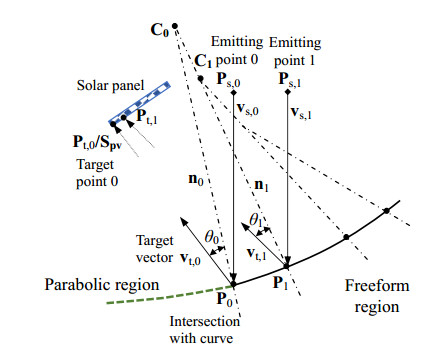
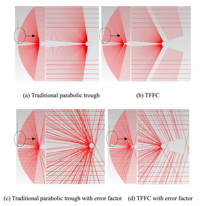
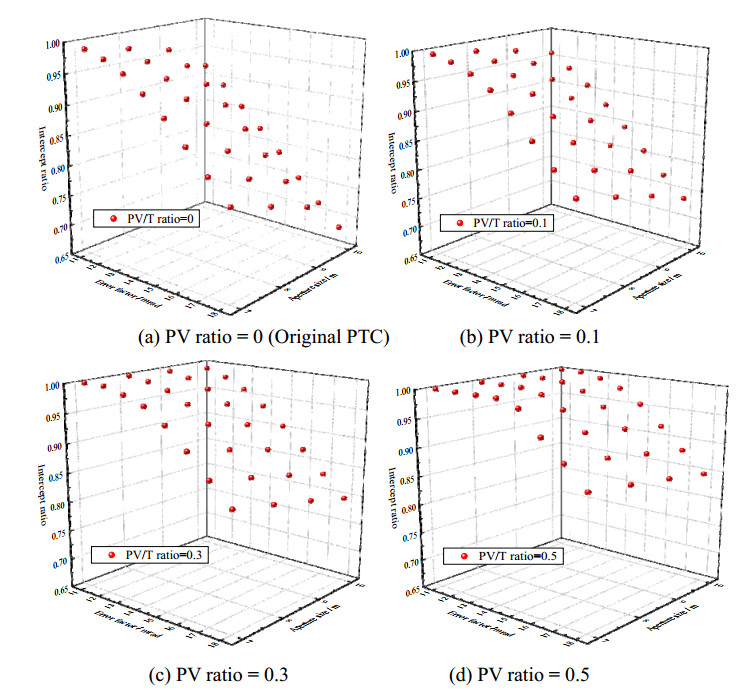
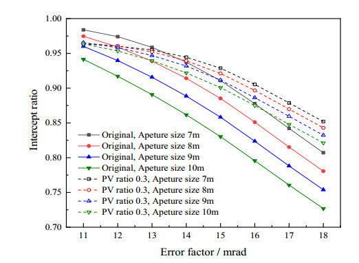
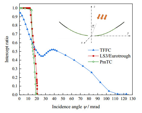
The developmental tendency of parabolic trough collector (PTC) is larger aperture area for energy harvest and novel optical design for higher solar concentration. Larger aperture faces a higher demand in tracking accuracy and lower tolerances with respect to wind loads, quality of mirrors, control, and mounting imprecisions. With the increase of reflection angle, the divergence size of concentrated focal spot gets enlarged on receiving surface, forming a Gaussian distribution. Receiving more energy and making best use of the concentrated solar power have become a key problem. In current study, a novel trough free-form solar concentrator (TFFC) has been developed by extending the aperture size with the aid of freeform optics and combined PV/thermal utilization. The structure model is composed by traditional parabolic trough with thermal tube, and extended freeform reflector with solar panel in slope configuration. The free-form surface is generated by geometric construction method for the sake of uniform heat flux distribution. The optical characteristics are validated by ray tracing method. The advantages will be revealed by compared with traditional system. The sensitivity analysis and error factors would be discussed as well. The initial results are promising and significant for the enhancement of trough type solar concentrator systems.
Citation: Xian-long Meng, Cun-liang Liu, Xiao-hui Bai, De-hai Kong, Kun Du. Improvement of the performance of parabolic trough solar concentrator using freeform optics and CPV/T design[J]. AIMS Energy, 2021, 9(2): 286-304. doi: 10.3934/energy.2021015
| [1] | Yi Tian . Approximate solution of initial boundary value problems for ordinary differential equations with fractal derivative. Mathematical Modelling and Control, 2022, 2(2): 75-80. doi: 10.3934/mmc.2022009 |
| [2] | Abduljawad Anwar, Shayma Adil Murad . On the Ulam stability and existence of Lp-solutions for fractional differential and integro-differential equations with Caputo-Hadamard derivative. Mathematical Modelling and Control, 2024, 4(4): 439-458. doi: 10.3934/mmc.2024035 |
| [3] | Ravindra Rao, Jagan Mohan Jonnalagadda . Existence of a unique solution to a fourth-order boundary value problem and elastic beam analysis. Mathematical Modelling and Control, 2024, 4(3): 297-306. doi: 10.3934/mmc.2024024 |
| [4] | Zhen Xin, Yuhe Yang, Qiaoxia Li . Controllability of nonlinear ordinary differential equations with non-instantaneous impulses. Mathematical Modelling and Control, 2022, 2(1): 1-6. doi: 10.3934/mmc.2022001 |
| [5] | K. Venkatachalam, M. Sathish Kumar, P. Jayakumar . Results on non local impulsive implicit Caputo-Hadamard fractional differential equations. Mathematical Modelling and Control, 2024, 4(3): 286-296. doi: 10.3934/mmc.2024023 |
| [6] | Iman Malmir . Novel closed-loop controllers for fractional nonlinear quadratic systems. Mathematical Modelling and Control, 2023, 3(4): 345-354. doi: 10.3934/mmc.2023028 |
| [7] | Hui Li, Nana Jin, Yu Zhang . Existence of nonoscillatory solutions for higher order nonlinear mixed neutral differential equations. Mathematical Modelling and Control, 2024, 4(4): 417-423. doi: 10.3934/mmc.2024033 |
| [8] | Mrutyunjaya Sahoo, Dhabaleswar Mohapatra, S. Chakraverty . Wave solution for time fractional geophysical KdV equation in uncertain environment. Mathematical Modelling and Control, 2025, 5(1): 61-72. doi: 10.3934/mmc.2025005 |
| [9] | Kexin Ouyang, Xinmin Qu, Huiqin Lu . Sign-changing and signed solutions for fractional Laplacian equations with critical or supercritical nonlinearity. Mathematical Modelling and Control, 2025, 5(1): 1-14. doi: 10.3934/mmc.2025001 |
| [10] | Zhenguo Luo, Liping Luo . New criteria for oscillation of damped fractional partial differential equations. Mathematical Modelling and Control, 2022, 2(4): 219-227. doi: 10.3934/mmc.2022021 |
The developmental tendency of parabolic trough collector (PTC) is larger aperture area for energy harvest and novel optical design for higher solar concentration. Larger aperture faces a higher demand in tracking accuracy and lower tolerances with respect to wind loads, quality of mirrors, control, and mounting imprecisions. With the increase of reflection angle, the divergence size of concentrated focal spot gets enlarged on receiving surface, forming a Gaussian distribution. Receiving more energy and making best use of the concentrated solar power have become a key problem. In current study, a novel trough free-form solar concentrator (TFFC) has been developed by extending the aperture size with the aid of freeform optics and combined PV/thermal utilization. The structure model is composed by traditional parabolic trough with thermal tube, and extended freeform reflector with solar panel in slope configuration. The free-form surface is generated by geometric construction method for the sake of uniform heat flux distribution. The optical characteristics are validated by ray tracing method. The advantages will be revealed by compared with traditional system. The sensitivity analysis and error factors would be discussed as well. The initial results are promising and significant for the enhancement of trough type solar concentrator systems.
Nonlinear equations arise always in electroanalytical chemistry with complex and esoteric nonlinear terms[1,2], though there are some advanced analytical methods to deal with nonlinear problems, for examples, the Gamma function method[3], Fourier spectral method[4], the reproducing kernel method[5], the perturbation method[6], the homotopy perturbation method[7,8], He's frequency formulation[9,10,11] and the dimensional method[12], chemists are always eager to have a simple one step method for nonlinear equations. This paper introduces an ancient Chinese algorithm called as the Ying Buzu algorithm[13] to solve nonlinear differential equations.
We first introduce the Taylor series method[14]. Considering the nonlinear differential equation:
| d2udx2+F(u)=0. | (0.1) |
The boundary conditions are
| dudx(a)=α, | (0.2) |
| u(b)=β. | (0.3) |
If u(a) is known, we can use an infinite Taylor series to express the exact solution[14]. We assume that
| u(a)=c. | (0.4) |
From (0.1), we have
| u″(a)=−F(u(a))=−F(c), |
| u‴(a)=−∂F(c)∂uu′(a)=−α∂F(c)∂u. |
Other higher order derivatives can be obtained with ease, and its Taylor series solution is
| u(x)=u(a)+(x−a)u′(a)+12!(x−a)2u″(a)+13!(x−a)3u‴(a)+...+1N!(x−a)Nu(N)(a), |
the constant c can be determined by the boundary condition of (0.3).
The Ying Buzu algorithm[15,16] was used to solve differential equations in 2006[13], it was further developed to He's frequency formulation for nonlinear oscillators[13,17,18,19,20,21,22,23] and Chun-Hui He's algorithm for numerical simulation[24].
As c in (0.4) is unknown, according to the Ying Buzu algorithm[13,15,16], we can assume two initial guesses:
| u1(a)=c1,u2(a)=c2. | (0.5) |
where c1 and c2 are given approximate values.
Using the initial conditions given in (0.2) and (0.5), we can obtain the terminal values:
| u(b,c1)=β1,u(b,c2)=β2. |
According to the Ying Buzu algorithm[6,7,8,9,10,11,12], the initial guess can be updated as
| u(a)est=c3=c1(β−β2)−c2(β−β1)(β−β2)−(β−β1), |
and its terminal value can be calculated as
| u(b,c3)=β3. |
For a given small threshold, ε, |β−β3|≤ε, we obtain u(a)=c3 as an approximate solution.
Here, we take Michaelis Menten dynamics as an example to solve the equation. Michaelis Menten reaction diffusion equation is considered as follows[25,26]:
| d2udx2−u1+u=0. | (0.6) |
The boundary conditions of it are as follows:
| dudx(0)=0,u(1)=1. | (0.7) |
We assume
| u(0)=c. |
From (0.6), we have
| u″(0)=c1+c, |
| u‴(0)=0, | (0.8) |
| u(4)=c(1+c)3. |
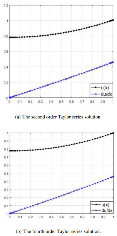
The 2nd order Taylor series solution is
| u(x)=u(0)+u′(0)1!x+u″(0)2!x2=c+c2(1+c)x2. |
In view of the boundary condition of (0.7), we have
| u(1)=c+c2(1+c)=1, | (0.9) |
solving c from (0.9) results in
| c=0.7808. |
So we obtain the following approximate solution
| u(x)=0.7808+0.2192x2. |
Similarly the fourth order Taylor series solution is
| u(x)=c+c2!(1+c)x2+c4!(1+c)3x4. |
Incorporating the boundary condition, u(1)=1, we have
| c+c2!(1+c)+c4!(1+c)3=1. | (0.10) |
We use the Ying Buzu algorithm to solve c, and write (0.10) in the form
| R(c)=c+c2(1+c)+c24(1+c)3−1. |
Assume the two initial solutions are
| c1=0.8,c2=0.5. |
We obtain the following residuals
| R1(0.8)=0.0279,R2(0.5)=−0.3271. |
By the Ying Buzu algorithm, c can be calculated as
| c=R2c1−R1c2R2−R1=0.0279×0.5+0.3271×0.80.0279+0.3271=0.7764. |
The exact solution of (0.10) is
| c=0.7758. |
The 4th order Taylor series solution is
| u(x)=0.7758+0.2192x2+0.0057x4. |
Figure 1 shows the Taylor series solutions, which approximately meet the requirement of the boundary condition at x=1.
Now we use the Ying Buzu algorithm by choosing two initial guesses
| u1(0)=0.5,u2(0)=1, |
which lead to u1=0.6726 and u2=1.2550, respectively, see Figure 2 (a) and (b).

It is obvious that the terminal value at x=1 deviates from u(1)=1 for each guess, according to the Ying Buzu algorithm, the initial guess can be updated as
| u3(0)=0.5×(1−1.2550)−1×(1−0.6726)(1−1.2550)−(1−0.6726)=0.7810. | (0.11) |
The shooting process using (0.11) results in
| u3(1)=1.0058, |
which deviates the exact value of u(1)=1 with a relative error of 0.5%, see Figure 3.

We can continue the iteration process to obtain a higher accuracy by using two following two guesses u1(0)=0.5, u3(0)=0.7810:
| u4(0)=0.5×(1−1.0058)−0.7810×(1−0.6726)(1−1.0058)−(1−0.6726)=0.7761. |
Using this updated initial value, the shooting process leads to the result
| u(1)=1.0001, |
so the approximate u(0)=0.7761 has only a relative error of 0.01%.
The above solution process couples the numerical method, and the ancient method can also be solved independently.
We assume that solution is
| u(x)=c+(1−c)x2. | (0.12) |
Equation (0.12) meets all boundary conditions.
The residual equation is
| R(x)=d2udx2−u1+u. |
It is easy to find that
| R(0)=2(1−c)−c1+c. |
We choose two guesses:
| c1=0.5,c2=1. |
We obtain the following residuals
| R1(0)=2(1−0.5)−0.51+0.5=23, |
| R2(0)=2(1−1)−11+1=−12. |
The Ying Buzu algorithm leads to the updated result:
| c=c2R1(0)−c1R2(0)R1(0)−R2(0)=23×1+12×0.523+12=0.7857. |
The relative error is 1.2%, and the process can continue if a higher accuracy is still needed.
The ancient Chinese algorithm provides a simple and straightforward tool to two-point boundary value problems arising in chemistry, and it can be used for fast insight into the solution property of a complex problem.
The authors declare that they have no conflicts of interest to this work.
| [1] |
Islam MT, Huda N, Abdullah AB, et al. (2018) A comprehensive review of state-of-the-art concentrating solar power (CSP) technologies: Current status and research trends. Renewable Sustainable Energy Rev 91: 987-1018. doi: 10.1016/j.rser.2018.04.097

|
| [2] |
Wang Q, Hu M, Yang H, et al. (2019) Energetic and exergetic analyses on structural optimized parabolic trough solar receivers in a concentrated solar-thermal collector system. Energy 171: 611-623. doi: 10.1016/j.energy.2018.12.211
|
| [3] |
Wang Q, Yang H, Zhong S, et al. (2020) Comprehensive experimental testing and analysis on parabolic trough solar receiver integrated with radiation shield. Appl Energy 268: 115004. doi: 10.1016/j.apenergy.2020.115004
|
| [4] |
Wang F, Cheng Z, Tan J, et al. (2017) Progress in concentrated solar power technology with parabolic trough collector system: A comprehensive review. Renewable Sustainable Energy Rev 79: 1314-1328. doi: 10.1016/j.rser.2017.05.174
|
| [5] |
Núnez Bootello JP, Schramm M, Silva AS, et al. (2017) Parametric trough solar collector with commercial evacuated receiver: Performance comparison at plant level. J Sol Energy Eng 139: 041014. doi: 10.1115/1.4036934
|
| [6] |
Bootello JPN, Price H, Perez MS, et al. (2016) Optical analysis of a two stage XX concentrator for parametric trough primary and tubular absorber with application in solar thermal energy trough power plants. J Sol Energy Eng 138: 041002-1. doi: 10.1115/1.4032944
|
| [7] |
Miñano JC, Benítez P, Santamaría A (2009) Free-form optics for illumination. Opt Rev 16: 99-102. doi: 10.1007/s10043-009-0017-4
|
| [8] |
Luo Y, Feng Z, Han Y, et al. (2010) Design of compact and smooth free-form optical system with uniform illuminance for LED source. Opt Express 18: 9055-9063. doi: 10.1364/OE.18.009055
|
| [9] |
Reimers J, Schiesser EM, Thompson K, et al. (2015) Comparison of freeform imaging spectrometer design forms using spectral full-field displays. Freeform Opt, FM3B. 3. doi: 10.1364/FREEFORM.2015.FM3B.3
|
| [10] |
Fournier F, Rolland J (2008) Optimization of freeform lightpipes for light-emitting-diode projectors. Appl Opt 47: 957-966. doi: 10.1364/AO.47.000957
|
| [11] |
Hernández M, Benítez P, Miñano J, et al. (2007) The XR nonimaging photovoltaic concentrator. Proceedings of SPIE, Nonimaging Optics and Efficient Illumination Systems Ⅳ, 667005-667010. doi: 10.1117/12.736897
|
| [12] |
Cui SF, Nicholas P, Liliana RD, et al. (2019) Silicone optical elements for cost-effective freeform solar concentration. Opt Express 27: A572-A580. doi: 10.1364/OE.27.00A572
|
| [13] | Cvetkovic A, Hernandez M, Benítez P, et al. (2008) The free form XR photovoltaic concentrator: a high performance SMS3D design. Proceedings of SPIE-The International Society for Optical Engineering: 7043. |
| [14] |
Hernández M, Benítez P, Miñano J, et al. (2007) XR: A high-performance PV concentrator. Proceedings of SPIE, 664904-664910. doi: 10.1117/12.736910
|
| [15] | Cvetkovića A, Hernandezb M, Beníteza P, et al. (2008) The SMS3D photovoltaic concentrator. Proceedings of SPIE-The International Society for Optical Engineering 7059: 705909.1-705909.12. |
| [16] | Miñano J, Hernandez M, Benítez P, et al. (2005) Free-form integrator array optics. Proceedings of the SPIE: 114-125. |
| [17] | Symko-Davies M (2007) High and low concentration for solar electric applications ii. Proceedings of SPIE-The International Society for Optical Engineering, 6339. |
| [18] | Zamora P, Cvetkovic A, Buljan M, et al. (2009) Advanced PV concentrators. Photovoltaic Specialists Conference (PVSC) 34th IEEE: 000929-000932. |
| [19] |
Benítez P, Miñano JC, Zamora P, et al. (2010) High performance Fresnel-based photovoltaic concentrator. Opt Express 18: A25-A40. doi: 10.1364/OE.18.000A25
|
| [20] |
Miñano JC, Benítez P, Zamora P, et al. (2013) Free-form optics for Fresnel-lens-based photovoltaic concentrators. Opt Express 21: A494-A502. doi: 10.1364/OE.21.00A494
|
| [21] | Alvarez JL, Hernandez M, Benitez P, et al. (2001) TIR-R concentrator: a new compact high-gain SMS design. Proc. SPIE 4446, Nonimaging Optics: Maximum Efficiency Light Transfer Ⅵ. |
| [22] |
Benítez P, Miñano JC (2007) The Future of illumination design. Opt Photonics News 18: 20-25. doi: 10.1364/OPN.18.5.000020
|
| [23] | Cheng D, Wang Y, Hua H (2010) Free form optical system design with differential equations. International Society for Optics and Photonics, 78490Q-78490Q-78498. |
| [24] |
Ries H, Muschaweck J (2002) Tailored freeform optical surfaces. JOSA A 19: 590-595. doi: 10.1364/JOSAA.19.000590
|
| [25] |
Fournier FR, Cassarly WJ, Rolland JP (2010) Fast freeform reflector generation using source-target maps. Opt Express 18: 5295-5304. doi: 10.1364/OE.18.005295
|
| [26] | Dross O, Mohedano R, Benitez P, et al. (2004) Review of SMS design methods and real-world applications. Proceedings of SPIE-The International Society for Optical Engineering 5529: 35-47. |
| [27] |
Tsai CY (2015) Improved irradiance distribution on high concentration solar cell using free-form concentrator. Sol Energy 115: 694-707. doi: 10.1016/j.solener.2015.03.032
|
| [28] |
Cheng Y, Fang F, Zhang X (2012) Design and manufacture of off-axis optical reflective integrator with faceted structure. Opt Eng 51: 4001. doi: 10.1117/1.OE.51.9.094001
|
| [29] |
Coventry JS, Lovegrove K (2003) Development of an approach to compare the 'value' of electrical and thermal output from a domestic pv/thermal system. Sol Energy 75: 63-72. doi: 10.1016/S0038-092X(03)00231-7
|
| 1. | Yi Tian, Approximate solution of initial boundary value problems for ordinary differential equations with fractal derivative, 2022, 2, 2767-8946, 75, 10.3934/mmc.2022009 | |
| 2. | Guang-Qing Feng, Jing-Yan Niu, The analysis for the dynamic pull-in of a micro-electromechanical system, 2022, 1461-3484, 146134842211455, 10.1177/14613484221145588 | |
| 3. | YONG-GANG KANG, SHUAI-JIA KOU, SI-REN SONG, YU-ZHEN CHANG, AN-YANG WANG, YONG-GANG CHEN, VIBRATION ANALYSIS OF HEAVY WEAPONS IN TRANSIT BY AIRCRAFT IN FRACTAL SPACE CONSIDERING LOCATION DEVIATION, 2024, 32, 0218-348X, 10.1142/S0218348X2450018X | |
| 4. | Jing-Yan Niu, Guang-Qing Feng, A mini-review on ancient mathematics’ modern applications with an emphasis on the old Babylonian mathematics for MEMS systems, 2024, 12, 2296-424X, 10.3389/fphy.2024.1532630 |
Figures(14) / Tables(1)

Xian-long Meng, Cun-liang Liu, Xiao-hui Bai, De-hai Kong, Kun Du. Improvement of the performance of parabolic trough solar concentrator using freeform optics and CPV/T design[J]. AIMS Energy, 2021, 9(2): 286-304. doi: 10.3934/energy.2021015

 DownLoad:
