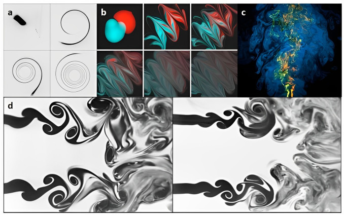
Mixing is the basis of stable and efficient combustion in air-breathing power systems, and it is also an important problem in fluid mechanics, which has been extensively studied from various perspectives. The purpose of this review is to investigate mixing mechanisms based on two commonly-used mixing indicators, namely $ c^i $ ($ c $ refers to concentration, and $ i $ is either 1 or 2, indicating first- or second-order statistics), with a focus on passive-scalar (PS) and variable-density (VD) mixing. For PS mixing, the flow is not influenced by the mixing process. By using first-order statistics with concentration as the core, the PS mixing mechanisms on lamella structures can be described as stretching enhancing diffusion and promoting mixing. On the other hand, second-order statistics represented by the scalar dissipation rate can investigate mixing mechanisms on specific type of flow structures described by the invariants of velocity gradient tensors and the rotation of principal strain axis. As such, it has been found that strain-dominated flow structures can promote mixing, while rotation-dominated flow structures hinder it. For VD mixing, it has two distinct characteristics: flow changes due to baroclinic vorticity, and the inherent velocity divergence alters the mixing indicators. Studies using first-order statistics center on the mixing time in different types of VD flows, leading to the discovery of new phenomena. For instance, the second baroclinic vorticity can promote stretching in shock bubble interactions. Studies on second-order statistics for VD mixing have defined several mixing indicators from the component-transport equation, which have been utilized in phenomenological studies on VD mixing. This review aims to provide an overview of mixing phenomena, mixing indicators, and mixing mechanisms, and proposes research directions for understanding the mixing characteristics, flow structures, and their relationship with specific combustion phenomena particularly by second-order statistics.
Citation: Xu Han, Bin Yu, Hong Liu. Mixing mechanisms in the view of mixing indicators: from passive-scalar mixing to variable-density mixing[J]. Metascience in Aerospace, 2024, 1(1): 1-37. doi: 10.3934/mina.2024001
Mixing is the basis of stable and efficient combustion in air-breathing power systems, and it is also an important problem in fluid mechanics, which has been extensively studied from various perspectives. The purpose of this review is to investigate mixing mechanisms based on two commonly-used mixing indicators, namely $ c^i $ ($ c $ refers to concentration, and $ i $ is either 1 or 2, indicating first- or second-order statistics), with a focus on passive-scalar (PS) and variable-density (VD) mixing. For PS mixing, the flow is not influenced by the mixing process. By using first-order statistics with concentration as the core, the PS mixing mechanisms on lamella structures can be described as stretching enhancing diffusion and promoting mixing. On the other hand, second-order statistics represented by the scalar dissipation rate can investigate mixing mechanisms on specific type of flow structures described by the invariants of velocity gradient tensors and the rotation of principal strain axis. As such, it has been found that strain-dominated flow structures can promote mixing, while rotation-dominated flow structures hinder it. For VD mixing, it has two distinct characteristics: flow changes due to baroclinic vorticity, and the inherent velocity divergence alters the mixing indicators. Studies using first-order statistics center on the mixing time in different types of VD flows, leading to the discovery of new phenomena. For instance, the second baroclinic vorticity can promote stretching in shock bubble interactions. Studies on second-order statistics for VD mixing have defined several mixing indicators from the component-transport equation, which have been utilized in phenomenological studies on VD mixing. This review aims to provide an overview of mixing phenomena, mixing indicators, and mixing mechanisms, and proposes research directions for understanding the mixing characteristics, flow structures, and their relationship with specific combustion phenomena particularly by second-order statistics.

| [1] |
Cetegen BM, Mohamad N (1993) Experiments on liquid mixing and reaction in a vortex. J Fluid Mech 249: 391–414. https://doi.org/10.1017/S0022112093001223 doi: 10.1017/S0022112093001223

|
| [2] |
Verzicco R, Orlandi P (1995) Mixedness in the formation of a vortex ring. Phys Fluids 7: 1513–1515. https://doi.org/10.1063/1.868538 doi: 10.1063/1.868538
|
| [3] |
Urzay J (2018) Supersonic combustion in air-breathing propulsion systems for hypersonic flight. Annu Rev Fluid Mech 50: 593–627. https://doi.org/10.1146/annurev-fluid-122316-045217 doi: 10.1146/annurev-fluid-122316-045217
|
| [4] | Ferri A, Libby PA, Zakkay V (1964) Theoretical and experimental investigation of supersonic combustion, in High Temperatures in Aeronautics, Elsevier, 55–118. https://doi.org/10.1016/B978-0-08-010558-1.50011-6 |
| [5] |
Ferri A (1973) Mixing-controlled supersonic combustion. Annu Rev Fluid Mech 5: 301–338. https://doi.org/10.1146/annurev.fl.05.010173.001505 doi: 10.1146/annurev.fl.05.010173.001505
|
| [6] | Gupta AK, Lilley DG, Syred N (1984) Swirl flows. Tunbridge Wells. |
| [7] |
Candel S, Durox D, Schuller T, et al. (2014) Dynamics of swirling flames. Annu Rev Fluid Mech 46: 147–173. https://doi.org/10.1146/annurev-fluid-010313-141300 doi: 10.1146/annurev-fluid-010313-141300
|
| [8] | Bahr D (1987) Technology for the design of high temperature rise combustors. J Propuls Power 3: 179–186. |
| [9] |
An Q, Steinberg AM (2019) The role of strain rate, local extinction, and hydrodynamic instability on transition between attached and lifted swirl flames. Combusti Flame 199: 267–278. https://doi.org/10.1016/j.combustflame.2018.10.029 doi: 10.1016/j.combustflame.2018.10.029
|
| [10] |
Caulfield C (2021) Layering, instabilities, and mixing in turbulent stratified flows. Annu Rev Fluid Mech 53: 113–145. https://doi.org/10.1146/annurev-fluid-042320-100458 doi: 10.1146/annurev-fluid-042320-100458
|
| [11] |
Crimaldi JP, Zimmer RK (2014) The physics of broadcast spawning in benthic invertebrates. Annu Rev Mar Sci 6: 1. https://doi.org/10.1146/annurev-marine-010213-135119 doi: 10.1146/annurev-marine-010213-135119
|
| [12] |
Mingotti N, Wood R, Noakes C, et al. (2020) The mixing of airborne contaminants by the repeated passage of people along a corridor. J Fluid Mech 903: A52. https://doi.org/10.1017/jfm.2020.671 doi: 10.1017/jfm.2020.671
|
| [13] |
Lohse D, Xia KQ (2010) Small-scale properties of turbulent rayleigh-bénard convection. Annu Rev Fluid Mech 42: 335–364. https://doi.org/10.1146/annurev-fluid-10908.165152 doi: 10.1146/annurev-fluid-10908.165152
|
| [14] |
Kolmogorov AN (1941) The local structure of turbulence in incompressible viscous fluid for very large reynolds numbers. Cr Acad Sci URSS 30: 301–305. https://doi.org/10.1007/978-94-011-3030-1_45 doi: 10.1007/978-94-011-3030-1_45
|
| [15] |
Batchelor GK (1959) Small-scale variation of convected quantities like temperature in turbulent fluid ${\text{Part 1}}$. general discussion and the case of small conductivity. J Fluid Mech 5: 113–133. https://doi.org/10.1017/S002211205900009X doi: 10.1017/S002211205900009X
|
| [16] |
Warhaft Z (2000) Passive scalars in turbulent flows. Annu Rev Fluid Mech 32: 203–240. https://doi.org/10.1146/annurev.fluid.32.1.203 doi: 10.1146/annurev.fluid.32.1.203
|
| [17] |
Schwertfirm F, Manhart M (2007) Dns of passive scalar transport in turbulent channel flow at high schmidt numbers. Int J Heat Fluid Fl 28: 1204–1214. https://doi.org/10.1016/j.ijheatfluidflow.2007.05.012 doi: 10.1016/j.ijheatfluidflow.2007.05.012
|
| [18] |
Dimotakis PE (2000) The mixing transition in turbulent flows. J Fluid Mech 409: 69–98. https://doi.org/10.1017/S0022112099007946 doi: 10.1017/S0022112099007946
|
| [19] |
Meunier P, Villermaux E (2003) How vortices mix. J Fluid Mech 476: 213–222. https://doi.org/10.1017/S0022112002003166 doi: 10.1017/S0022112002003166
|
| [20] |
Souzy M, Zaier I, Lhuissier H, et al. (2018) Mixing lamellae in a shear flow. J Fluid Mech 838: R3. https://doi.org/10.1017/jfm.2017.916 doi: 10.1017/jfm.2017.916
|
| [21] |
Buaria D, Clay MP, Sreenivasan KR, et al. (2021) Turbulence is an ineffective mixer when schmidt numbers are large. Phys Rev Lett 126: 074501. https://doi.org/10.1103/PhysRevLett.126.074501 doi: 10.1103/PhysRevLett.126.074501
|
| [22] |
Raynal F, Gence JN (1997) Energy saving in chaotic laminar mixing. Int J Heat Mass Trans 40: 3267–3273. https://doi.org/10.1016/S0017-9310(96)00383-3 doi: 10.1016/S0017-9310(96)00383-3
|
| [23] |
Dimotakis PE (2005) Turbulent mixing. Annu Rev Fluid Mech 37: 329–356. https://doi.org/10.1146/annurev.fluid.36.050802.122015 doi: 10.1146/annurev.fluid.36.050802.122015
|
| [24] |
Thiffeault JL (2012) Using multiscale norms to quantify mixing and transport. Nonlinearity 25: R1. https://doi.org/10.1088/0951-7715/25/2/R1 doi: 10.1088/0951-7715/25/2/R1
|
| [25] |
Duplat J, Jouary A, Villermaux E (2010) Entanglement rules for random mixtures. Phys Rev Lett 105: 034504. https://doi.org/10.1103/PhysRevLett.105.034504 doi: 10.1103/PhysRevLett.105.034504
|
| [26] |
Kree M, Duplat J, Villermaux E (2013) The mixing of distant sources. Phys Fluids 25: 091103. https://doi.org/10.1063/1.4820015 doi: 10.1063/1.4820015
|
| [27] |
Villermaux E, Rehab H (2000) Mixing in coaxial jets. J Fluid Mech 425: 161–185. https://doi.org/10.1017/S002211200000210X doi: 10.1017/S002211200000210X
|
| [28] | Vidick B (1989) Critical mixing parameters for good control of cement slurry quality. in SPE Production Operations Symposium. OnePetro. https://doi.org/10.2118/18895-PA |
| [29] |
Poulain S, Villermaux E, Bourouiba L (2018) Ageing and burst of surface bubbles. J Fluid Mech 851: 636–671. https://doi.org/10.1017/jfm.2018.471 doi: 10.1017/jfm.2018.471
|
| [30] | Marble F (1985) Growth of a diffusion flame in the field of a vortex, in Recent advances in the aerospace sciences, Springer, 395–413. https://doi.org/10.1007/978-1-4684-4298-4_19 |
| [31] |
Villermaux E (2019) Mixing versus stirring. Annu Rev Fluid Mech 51: 245–273. https://doi.org/10.1146/annurev-fluid-010518-040306 doi: 10.1146/annurev-fluid-010518-040306
|
| [32] |
Ranz WE (1979) Applications of a stretch model to mixing, diffusion, and reaction in laminar and turbulent flows. AIChE J 25: 41–47. https://doi.org/10.1002/aic.690250105 doi: 10.1002/aic.690250105
|
| [33] | Marble FE, Broadwell JE (1977) The coherent flame model for turbulent chemical reactions. Purdue Univ Lafayette in project squid head quaters. Tech Rep. Available from: https://api.semanticscholar.org/CorpusID:45411925. |
| [34] |
Villermaux E, Duplat J (2003) Mixing is an aggregation process. Comptes Rendus Mécanique 331: 515–523. https://doi.org/10.1016/S1631-0721(03)00110-4 doi: 10.1016/S1631-0721(03)00110-4
|
| [35] |
Duplat J, Villermaux E (2008) Mixing by random stirring in confined mixtures. J Fluid Mech 617: 51–86. https://doi.org/10.1017/S0022112008003789 doi: 10.1017/S0022112008003789
|
| [36] |
Duplat J, Innocenti C, Villermaux E (2010) A nonsequential turbulent mixing process. Phys Fluids 22: 035104. https://doi.org/10.1063/1.3319821 doi: 10.1063/1.3319821
|
| [37] |
Haller G (2015) Lagrangian coherent structures. Annu Rev Fluid Mech 47: 137–162. https://doi.org/10.1146/annurev-fluid-010313-141322 doi: 10.1146/annurev-fluid-010313-141322
|
| [38] |
Hang H, Yu B, Xiang Y, et al. (2020) An objective-adaptive refinement criterion based on modified ridge extraction method for finite-time lyapunov exponent (ftle) calculation. J Visual 23: 81–95. https://doi.org/10.1007/S12650-019-00605-1 doi: 10.1007/S12650-019-00605-1
|
| [39] |
Liang G, Yu B, Zhang B, et al. (2019) Hidden flow structures in compressible mixing layer and a quantitative analysis of entrainment based on lagrangian method. J Hydrodyn 31: 256–265. https://doi.org/10.1017/jfm.2020.295 doi: 10.1017/jfm.2020.295
|
| [40] |
Zheng Z, Fan Z, Wang Z, et al. (2021) Lagrangian visualization of mixing enhancement induced by finite-time stretching in compressible vortex interaction. J Visual 24: 19–28. https://doi.org/10.1007/s12650-020-00698-z doi: 10.1007/s12650-020-00698-z
|
| [41] |
Götzfried P, Emran MS, Villermaux E, et al. (2019) Comparison of lagrangian and eulerian frames of passive scalar turbulent mixing. Phys Rev Fluids 4: 044607. https://doi.org/10.1103/PhysRevFluids.4.044607 doi: 10.1103/PhysRevFluids.4.044607
|
| [42] |
Meunier P, Villermaux E (2022) The diffuselet concept for scalar mixing. J Fluid Mech 951: A33. https://doi.org/10.1017/jfm.2022.771 doi: 10.1017/jfm.2022.771
|
| [43] |
Meunier P, Villermaux E (2010) The diffusive strip method for scalar mixing in two dimensions. J Fluid Mechanics 662: 134–172. https://doi.org/10.1017/S0022112010003162 doi: 10.1017/S0022112010003162
|
| [44] |
Martínez-Ruiz D, Meunier P, Favier B, et al.(2018) The diffusive sheet method for scalar mixing. J Fluid Mech 837: 230–257. https://doi.org/10.1017/S0022112010003162 doi: 10.1017/S0022112010003162
|
| [45] |
Sen S, Singh P, Heyman J, et al. (2020) The impact of stretching-enhanced mixing and coalescence on reactivity in mixing-limited reactive flows. Phys Fluids 32: 106602, 2020. https://doi.org/10.1063/5.0022798 doi: 10.1063/5.0022798
|
| [46] |
Heyman J, Lester DR, Turuban R, et al. (2020) Stretching and folding sustain microscale chemical gradients in porous media. P Natl Acad Sci 117: 13 359–13 365. https://doi.org/10.1073/pnas.2002858117 doi: 10.1073/pnas.2002858117
|
| [47] |
Guilbert E, Almarcha C, Villermaux E (2021) Chemical reaction for mixing studies. Phys Rev Fluids 6: 114501. https://doi.org/10.1103/PhysRevFluids.6.114501 doi: 10.1103/PhysRevFluids.6.114501
|
| [48] |
Guilbert E, Metzger B, Villermaux E (2022) Chemical production on a deforming substrate. J Fluid Mech 934: R1. https://doi.org/10.1017/jfm.2021.1122 doi: 10.1017/jfm.2021.1122
|
| [49] |
Buch KA, Dahm WJ (1996) Experimental study of the fine-scale structure of conserved scalar mixing in turbulent shear flows. part 1. sc [dbl greater-than sign] 1. J Fluid Mech 317: 21–71. https://doi.org/10.1017/s0022112096000651 doi: 10.1017/s0022112096000651
|
| [50] |
Cetegen B, Aguirre J (1990) Analysis of molecular mixing and chemical reaction in a vortex pair. Phys Fluids 2: 2211–2216. https://doi.org/10.1063/1.857807 doi: 10.1063/1.857807
|
| [51] |
Basu S, Barber T, Cetegen B (2007) Computational study of scalar mixing in the field of a gaseous laminar line vortex. Phys Fluids 19: 053601. https://doi.org/10.1063/1.2732454 doi: 10.1063/1.2732454
|
| [52] |
Flohr P, Vassilicos J (1997) Accelerated scalar dissipation in a vortex. J Fluid Mech 348: 295–317. https://doi.org/10.1017/S0022112097006927 doi: 10.1017/S0022112097006927
|
| [53] |
Bilger R (1976) The structure of diffusion flames. Combust Sci Technol 13: 155–170. https://doi.org/10.1080/00102207608946733 doi: 10.1080/00102207608946733
|
| [54] |
Bilger RW (1989) Turbulent diffusion flames. Annu Rev Fluid Mech 21: 101–135. https://doi.org/10.1146/annurev.fl.21.010189.000533 doi: 10.1146/annurev.fl.21.010189.000533
|
| [55] |
Yeung P, Girimaji S, Pope S (1990) Straining and scalar dissipation on material surfaces in turbulence: implications for flamelets. Combust Flame 79: 340–365. https://doi.org/10.1016/0010-2180(90)90145-H doi: 10.1016/0010-2180(90)90145-H
|
| [56] |
Kim SH, Pitsch H (2007) Scalar gradient and small-scale structure in turbulent premixed combustion. Phys Fluids 19: 115104. https://doi.org/10.1063/1.2784943 doi: 10.1063/1.2784943
|
| [57] |
Boratav O, Elghobashi S, Zhong R (1996) On the alignment of the $alpha$-strain and vorticity in turbulent nonpremixed flames. Phys Fluids 8: 2251–2253. https://doi.org/10.1063/1.869000 doi: 10.1063/1.869000
|
| [58] |
Boratav O, Elghobashi S, Zhong R (1998) On the alignment of strain, vorticity and scalar gradient in turbulent, buoyant, nonpremixed flames. Phys Fluids 10: 2260–2267. https://doi.org/10.1063/1.869747 doi: 10.1063/1.869747
|
| [59] |
Attili A, Bisetti F (2019) Statistics of scalar dissipation and strain/vorticity/scalar gradient alignment in turbulent nonpremixed jet flames. Flow Turbul Combust 103: 625–642. https://doi.org/10.1007/s10494-019-00044-w doi: 10.1007/s10494-019-00044-w
|
| [60] |
McManus TA, Sutton JA (2022) Conditional analysis of temperature and strain rate effects on dissipation structure in turbulent non-premixed jet flames. P Combust Inst. https://doi.org/10.1016/j.proci.2022.07.052 doi: 10.1016/j.proci.2022.07.052
|
| [61] |
Chakraborty N, Swaminathan N (2007) Influence of the damköhler number on turbulence-scalar interaction in premixed flames. i. physical insight. Phys Fluids 19: 045103. https://doi.org/10.1063/1.2714070 doi: 10.1063/1.2714070
|
| [62] |
Zhao S, Er-Raiy A, Bouali Z, et al. (2018) Dynamics and kinematics of the reactive scalar gradient in weakly turbulent premixed flames. Combust Flame 198: 436–454. https://doi.org/10.1016/j.combustflame.2018.10.002 doi: 10.1016/j.combustflame.2018.10.002
|
| [63] |
Batchelor GK (1952) The effect of homogeneous turbulence on material lines and surfaces. Proc Math Phys Sci 213: 349–366. https://doi.org/10.1098/rspa.1952.0130 doi: 10.1098/rspa.1952.0130
|
| [64] |
Girimaji S, Pope S (1990) 'Material-element deformation in isotropic turbulence. J Fluid Mech 220: 427–458. https://doi.org/10.1017/S0022112090003330 doi: 10.1017/S0022112090003330
|
| [65] |
Dresselhaus E, Tabor M (1992) The kinematics of stretching and alignment of material elements in general flow fields. J Fluid Mech 236: 415–444. https://doi.org/10.1017/S0022112092001460 doi: 10.1017/S0022112092001460
|
| [66] |
Lapeyre G, Klein P, Hua B (1999) Does the tracer gradient vector align with the strain eigenvectors in 2d turbulence? Phys Fluids 11: 3729–3737. https://doi.org/10.1063/1.870234 doi: 10.1063/1.870234
|
| [67] |
Klein P, Hua BL, Lapeyre G (2000) Alignment of tracer gradient vectors in 2d turbulence. Physica D 146: 246–260. https://doi.org/10.1016/S0167-2789(00)00119-6 doi: 10.1016/S0167-2789(00)00119-6
|
| [68] |
Swaminathan N, Grout R (2006) Interaction of turbulence and scalar fields in premixed flames. Phys Fluids 18: 045102. https://doi.org/10.1063/1.2186590 doi: 10.1063/1.2186590
|
| [69] |
Minamoto Y, Jigjid K, Igari R, et al. (2022) Effect of flame–flame interaction on scalar pdf in turbulent premixed flames. Combust Flame 239: 111660. https://doi.org/10.1016/j.combustflame.2021.111660 doi: 10.1016/j.combustflame.2021.111660
|
| [70] |
Holzner M, Lüthi B (2011) Laminar superlayer at the turbulence boundary. Phys Rev Lett 106, : 134503. https://doi.org/10.1103/PhysRevLett.106.134503 doi: 10.1103/PhysRevLett.106.134503
|
| [71] |
Townsend AA (1951) The diffusion of heat spots in isotropic turbulence. Proc Math Phys Sci 209: 418–430. https://doi.org/10.1098/rspa.1951.0216 doi: 10.1098/rspa.1951.0216
|
| [72] |
Cocke W (1969) Turbulent hydrodynamic line stretching: consequences of isotropy. Phys Fluids 12: 2488–2492. https://doi.org/10.1063/1.1692385 doi: 10.1063/1.1692385
|
| [73] |
Ashurst WT, Kerstein A, Kerr R, et al. (1987) Alignment of vorticity and scalar gradient with strain rate in simulated navier–stokes turbulence. Phys Fluids 30: 2343–2353. https://doi.org/10.1063/1.866513 doi: 10.1063/1.866513
|
| [74] |
Vincent A, Meneguzzi M (1991) The spatial structure and statistical properties of homogeneous turbulence. J Fluid Mech 225: 1–20. https://doi.org/10.1017/S0022112091001957 doi: 10.1017/S0022112091001957
|
| [75] |
Carter HH, Okubo A (1972) Longitudinal dispersion in non-uniform flow. Water Resour Res 8: 648–660. https://doi.org/10.1029/WR008i003p00648 doi: 10.1029/WR008i003p00648
|
| [76] |
Weiss J (1991) The dynamics of enstrophy transfer in two-dimensional hydrodynamics. Physica D 48: 273–294. https://doi.org/10.1016/0167-2789(91)90088-Q doi: 10.1016/0167-2789(91)90088-Q
|
| [77] | Hunt JC, Wray AA, Moin P (1988) Eddies, streams, and convergence zones in turbulent flows. Studying turbulence using numerical simulation databases, 2. Proceedings of the 1988 summer program. Available from: https://ntrs.nasa.gov/citations/19890015184 |
| [78] |
Basdevant C, Philipovitch T (1994) On the validity of the "weiss criterion" in two-dimensional turbulence. Physica D 73: 17–30. https://doi.org/10.1016/0167-2789(94)90222-4 doi: 10.1016/0167-2789(94)90222-4
|
| [79] |
Hua B, Klein P (1998) An exact criterion for the stirring properties of nearly two-dimensional turbulence. Physica D 113: 98–110. https://doi.org/10.1016/S0167-2789(97)00143-7 doi: 10.1016/S0167-2789(97)00143-7
|
| [80] |
Galanti B, Gibbon J, Heritage M (1997) Vorticity alignment results for the three-dimensional euler and navier-stokes equations. Nonlinearity 10: 1675. https://doi.org/10.1088/0951-7715/10/6/013 doi: 10.1088/0951-7715/10/6/013
|
| [81] |
Ohkitani K, Kishiba S (1995) Nonlocal nature of vortex stretching in an inviscid fluid. Phys Fluids 7: 411–421. https://doi.org/10.1063/1.868638 doi: 10.1063/1.868638
|
| [82] |
Tsinober A, Ortenberg M, Shtilman L (1999) On depression of nonlinearity in turbulence. Phys Fluids 11: 2291–2297. https://doi.org/10.1063/1.870091 doi: 10.1063/1.870091
|
| [83] |
Wacks DH, Chakraborty N, Klein M, et al. (2016) Flow topologies in different regimes of premixed turbulent combustion: A direct numerical simulation analysis. Phys Rev Fluids 1: 083401. https://doi.org/10.1103/PhysRevFluids.1.083401 doi: 10.1103/PhysRevFluids.1.083401
|
| [84] |
Meneveau C (2011) Lagrangian dynamics and models of the velocity gradient tensor in turbulent flows. Annu Rev Fluid Mech 43: 219–245. https://doi.org/10.1146/annurev-fluid-122109-160708 doi: 10.1146/annurev-fluid-122109-160708
|
| [85] |
Jeong J, Hussain F (1995) On the identification of a vortex. J Fluid Mech 285: 69–94. https://doi.org/10.1017/S0022112095000462 doi: 10.1017/S0022112095000462
|
| [86] |
Chong MS, Perry AE, Cantwell BJ (1990) A general classification of three-dimensional flow fields. Phys Fluids A 2: 765–777. https://doi.org/10.1063/1.857730 doi: 10.1063/1.857730
|
| [87] |
Perry AE, Chong MS (1987) A description of eddying motions and flow patterns using critical-point concepts. Annu Rev Fluid Mech 19: 125–155. https://doi.org/10.1146/annurev.fl.19.010187.001013 doi: 10.1146/annurev.fl.19.010187.001013
|
| [88] |
Danish M, Suman S, Girimaji SS (2016) Influence of flow topology and dilatation on scalar mixing in compressible turbulence. J Fluid Mech 793: 633–655. https://doi.org/10.1017/jfm.2016.145 doi: 10.1017/jfm.2016.145
|
| [89] |
Gao X, Bermejo-Moreno I, Larsson J (2020) Parametric numerical study of passive scalar mixing in shock turbulence interaction. J Fluid Mech 895: A21. https://doi.org/10.1017/jfm.2020.292 doi: 10.1017/jfm.2020.292
|
| [90] |
Cifuentes L, Dopazo C, Martin J, et al. (2014) Local flow topologies and scalar structures in a turbulent premixed flame. Phys Fluids 26: 065108. https://doi.org/10.1063/1.4884555 doi: 10.1063/1.4884555
|
| [91] |
Han W, Scholtissek A, Dietzsch F, et al. (2019) Influence of flow topology and scalar structure on flame-tangential diffusion in turbulent non-premixed combustion. Combust Flame 206: 21–36. https://doi.org/10.1016/j.combustflame.2019.04.038 doi: 10.1016/j.combustflame.2019.04.038
|
| [92] |
Heyman J, Lester D, Le Borgne T (2021) Scalar signatures of chaotic mixing in porous media. Phys Rev Lett 126: 034505. https://doi.org/10.1103/PhysRevLett.126.034505 doi: 10.1103/PhysRevLett.126.034505
|
| [93] |
Waitz I, Qiu Y, Manning T, et al. (1997) Enhanced mixing with streamwise vorticity. Prog Aerosp Sci 33: 323–351. https://doi.org/10.1016/S0376-0421(96)00008-5 doi: 10.1016/S0376-0421(96)00008-5
|
| [94] |
Vergine F, Ground C, Maddalena L (2016) Turbulent kinetic energy decay in supersonic streamwise interacting vortices. J Fluid Mech 807: 353–385. https://doi.org/10.1017/jfm.2016.611 doi: 10.1017/jfm.2016.611
|
| [95] |
Wu Z, He M, Yu B, et al. (2022) A circulation prediction model for ramp and vortex generator in supersonic flow: A numerical study. Aerosp Sci Technol 127: 107688. https://doi.org/10.1016/j.ast.2022.107688 doi: 10.1016/j.ast.2022.107688
|
| [96] |
Wang Z, Yu B, Zhang B, et al. (2021) Kinematic and mixing characteristics of vortex interaction induced by a vortex generator model: a numerical study. Appl Math Mech 42: 387–404. https://doi.org/10.1007/s10483-021-2711-5 doi: 10.1007/s10483-021-2711-5
|
| [97] |
Schetz JA, Maddalena L, Burger SK (2010) Molecular weight and shock-wave effects on transverse injection in supersonic flow. J Propuls Power 26: 1102–1113. https://doi.org/10.2514/1.49355 doi: 10.2514/1.49355
|
| [98] |
Tew DE, Hermanson JC, Waitz IA (2004) Impact of compressibility on mixing downstream of lobed mixers. AIAA J 42: 2393–2396. https://doi.org/10.2514/1.11004 doi: 10.2514/1.11004
|
| [99] |
Brouillette M (2002) The richtmyer-meshkov instability. Annu Rev Fluid Mech 34: 445–468. https://doi.org/10.1146/annurev.fluid.34.090101.162238 doi: 10.1146/annurev.fluid.34.090101.162238
|
| [100] |
Zhou Y (2017) Rayleigh–taylor and richtmyer–meshkov instability induced flow, turbulence, and mixing. ii. Phys Rep 723: 1–160. https://doi.org/10.1016/j.physrep.2017.07.008 doi: 10.1016/j.physrep.2017.07.008
|
| [101] |
Zhou Y (2017) Rayleigh–taylor and richtmyer–meshkov instability induced flow, turbulence, and mixing. i. Phys Rep 720-722: 1–136. https://doi.org/10.1016/j.physrep.2017.07.005 doi: 10.1016/j.physrep.2017.07.005
|
| [102] |
Peng G, Zabusky NJ, Zhang S (2003) Vortex-accelerated secondary baroclinic vorticity deposition and late-intermediate time dynamics of a two-dimensional richtmyer–meshkov interface. Phys Fluids 15: 3730–3744. https://doi.org/10.1063/1.1621628 doi: 10.1063/1.1621628
|
| [103] |
Livescu D (2020) Turbulence with large thermal and compositional density variations. Annu Rev Fluid Mech 52: 309-341. https://doi.org/10.1146/annurev-fluid-010719-060114 doi: 10.1146/annurev-fluid-010719-060114
|
| [104] |
Weber C, Haehn N, Oakley J, et al. (2012) Turbulent mixing measurements in the richtmyer-meshkov instability. Phys Fluids 24: 074105. https://doi.org/10.1063/1.4733447 doi: 10.1063/1.4733447
|
| [105] |
Mikaelian KO (1998) Analytic approach to nonlinear rayleigh-taylor and richtmyer-meshkov instabilities. Phys Rev Lett 80: 508–511. https://doi.org/10.1103/PhysRevLett.80.508 doi: 10.1103/PhysRevLett.80.508
|
| [106] |
Zabusky NJ (1999) Vortex paradigm for accelerated inhomogeneous flows: Visiometrics for the rayleigh-taylor and richtmyer-meshkov environments. Annu Rev Fluid Mech 31: 495–536. https://doi.org/10.1146/annurev.fluid.31.1.495 doi: 10.1146/annurev.fluid.31.1.495
|
| [107] |
Kumar S, Orlicz G, Tomkins C, et al. (2005) Stretching of material lines in shock-accelerated gaseous flows. Phys Fluids 17: 082107. https://doi.org/10.1063/1.2031347 doi: 10.1063/1.2031347
|
| [108] |
Zhou Y, Cabot WH, Thornber B (2016) Asymptotic behavior of the mixed mass in rayleigh–taylor and richtmyer–meshkov instability induced flows. Phys Plasmas 23: 052712. https://doi.org/10.1063/1.4951018 doi: 10.1063/1.4951018
|
| [109] |
Richtmyer RD (1960) Taylor instability in shock acceleration of compressible fluids. Commun Pure Appl Math 13: 297–319. https://doi.org/10.1002/cpa.3160130207 doi: 10.1002/cpa.3160130207
|
| [110] |
Meshkov E (1969) Instability of the interface of two gases accelerated by a shock wave. Fluid Dyn 4: 101–104. https://doi.org/10.1007/BF01015969 doi: 10.1007/BF01015969
|
| [111] |
Klein RI, McKee CF, Colella P (1994) On the hydrodynamic interaction of shock waves with interstellar clouds. 1: Nonradiative shocks in small clouds. Astrophys J 420: 213–236. https://doi.org/10.1086/173554 doi: 10.1086/173554
|
| [112] |
Cabot WH, Cook AW (2006) Reynolds number effects on rayleigh–taylor instability with possible implications for type ia supernovae. Nat Phys 2: 562–568. https://doi.org/10.1038/nphys361 doi: 10.1038/nphys361
|
| [113] |
Lindl JD, McCrory RL, Campbell EM (1992) Progress toward ignition and burn propagation in inertial confinement fusion. Phys Today 45: 32–40. https://doi.org/10.1063/1.881318 doi: 10.1063/1.881318
|
| [114] |
EOran ES, Gamezo VN (2007) Origins of the deflagration-to-detonation transition in gas-phase combustion. Combust Flame 148: 4–47. https://doi.org/10.1016/j.combustflame.2006.07.010 doi: 10.1016/j.combustflame.2006.07.010
|
| [115] |
Yang J, Kubota T, Zukoski EE (1994) A model for characterization of a vortex pair formed by shock passage over a light-gas inhomogeneity. J Fluid Mech 258: 217–244. https://doi.org/10.1017/S0022112094003307 doi: 10.1017/S0022112094003307
|
| [116] |
Yu B, He M, Zhang B, et al. (2020) Two-stage growth mode for lift-off mechanism in oblique shock-wave/jet interaction. Phys Fluids 32: 116105. https://doi.org/10.1063/5.0022449 doi: 10.1063/5.0022449
|
| [117] |
Zhang B, Liu H, Yu B, et al. (2022) Numerical investigation on combustion-enhancement strategy in shock–fuel jet interaction. AIAA J 60: 393–410. https://doi.org/10.2514/1.J060168 doi: 10.2514/1.J060168
|
| [118] |
Zhang B, Chen H, Yu B, et al. (2019) Molecular simulation on viscous effects for microscale combustion in reactive shock-bubble interaction. Combust Flame 208: 351–363. https://doi.org/10.1016/j.combustflame.2019.07.001 doi: 10.1016/j.combustflame.2019.07.001
|
| [119] |
Liu H, Yu B, Chen H, et al. (2020) Contribution of viscosity to the circulation deposition in the richtmyer–meshkov instability. J Fluid Mech 895: A10. https://doi.org/10.1017/jfm.2020.295 doi: 10.1017/jfm.2020.295
|
| [120] |
Wang Z, Yu B, Chen H, et al. (2018) Scaling vortex breakdown mechanism based on viscous effect in shock cylindrical bubble interaction. Phys Fluids 30: 126103. https://doi.org/10.1063/1.5051463 doi: 10.1063/1.5051463
|
| [121] |
Ding J, Si T, Yang J, et al. (2017) Measurement of a richtmyer-meshkov instability at an air-sf 6 interface in a semiannular shock tube. Phys Rev Lett 119: 014501. https://doi.org/10.1103/PhysRevLett.119.014501 doi: 10.1103/PhysRevLett.119.014501
|
| [122] |
Cook AW, Dimotakis PE (2001) Transition stages of rayleigh–taylor instability between miscible fluids. J Fluid Mech 443: 69–99. https://doi.org/10.1017/S0022112002007802 doi: 10.1017/S0022112002007802
|
| [123] |
Cook AW, Cabot W, Miller PL (2004) The mixing transition in rayleigh–taylor instability. J Fluid Mech 511: 333–362. https://doi.org/10.1017/S0022112004009681 doi: 10.1017/S0022112004009681
|
| [124] |
Ristorcelli J, Clark T (2004) Rayleigh–taylor turbulence: self-similar analysis and direct numerical simulations. J Fluid Mech 507: 213–253. https://doi.org/10.1017/S0022112004008286 doi: 10.1017/S0022112004008286
|
| [125] |
Samtaney R, Zabusky NJ (1993) On shock polar analysis and analytical expressions for vorticity deposition in shock-accelerated density-stratified interfaces. Phys Fluids A: Fluid Dyn 5: 1285–1287. https://doi.org/10.1063/1.858618 doi: 10.1063/1.858618
|
| [126] |
Marugan-Cruz C, Rodriguez-Rodriguez J, Martinez-Bazan C (2013) Formation regimes of vortex rings in negatively buoyant starting jets. J Fluid Mech 716: 470–486. https://doi.org/10.1017/jfm.2012.554 doi: 10.1017/jfm.2012.554
|
| [127] |
Soteriou MC, Ghoniem AF (1995) Effects of the free stream density ratio on free and forced spatially developing shear layers. Phys Fluids 7: 2036–2051. https://doi.org/10.1063/1.868451 doi: 10.1063/1.868451
|
| [128] |
Livescu D, Ristorcelli J, Petersen M, et al. (2010) New phenomena in variable-density rayleigh–taylor turbulence. Phys Scripta 2010: 014015. https://doi.org/10.1088/0031-8949/2010/T142/014015 doi: 10.1088/0031-8949/2010/T142/014015
|
| [129] |
Zhai Z, Si T, Luo X, et al. (2011) On the evolution of spherical gas interfaces accelerated by a planar shock wave. Phys Fluids 23: 084104. https://doi.org/10.1063/1.3623272 doi: 10.1063/1.3623272
|
| [130] |
Si T, Long T, Zhai Z, et al. (2015) Experimental investigation of cylindrical converging shock waves interacting with a polygonal heavy gas cylinder. J Fluid Mech 784: 225–251. https://doi.org/10.1017/jfm.2015.581 doi: 10.1017/jfm.2015.581
|
| [131] |
Luo X, Wang M, Si T, et al. (2015) On the interaction of a planar shock with an polygon. J Fluid Mech 773: 366–394. https://doi.org/10.1017/jfm.2015.257 doi: 10.1017/jfm.2015.257
|
| [132] |
Ding J, Si T, Chen M, et al. (2017) On the interaction of a planar shock with a three-dimensional light gas cylinder. J Fluid Mech 828: 289–317. https://doi.org/10.1017/jfm.2017.528 doi: 10.1017/jfm.2017.528
|
| [133] |
Li D, Guan B, Wang G (2022) Effects of interface diffusion and shock strength on shock-accelerated sf6 cylinder. Phys Fluids 34: 076109. https://doi.org/10.1063/5.0099353 doi: 10.1063/5.0099353
|
| [134] |
Vorobieff P, Rightley PM, Benjamin RF (1998) Power-law spectra of incipient gas-curtain turbulence. Phys Rev Lett 81: 2240. https://doi.org/10.1103/PhysRevLett.81.2240 doi: 10.1103/PhysRevLett.81.2240
|
| [135] |
Niederhaus JH, Greenough J, Oakley J, et al. (2008) A computational parameter study for the three-dimensional shock–bubble interaction. J Fluid Mech 594: 85–124. https://doi.org/10.1017/S0022112007008749 doi: 10.1017/S0022112007008749
|
| [136] |
Lombardini M, Pullin D, Meiron D (2012) Transition to turbulence in shock-driven mixing: a mach number study. J Fluid Mech 690: 203–226. https://doi.org/10.1017/jfm.2011.425 doi: 10.1017/jfm.2011.425
|
| [137] |
Oggian T, Drikakis D, Youngs D, et al. (2015) Computing multi-mode shock-induced compressible turbulent mixing at late times. J Fluid Mech 779: 411–431. https://doi.org/10.1017/jfm.2015.392 doi: 10.1017/jfm.2015.392
|
| [138] |
Liu H, Yu B, Zhang B, et al. (2020) On mixing enhancement by secondary baroclinic vorticity in shock bubble interaction. J Fluid Mech 931: A17. https://doi.org/10.1017/jfm.2021.923 doi: 10.1017/jfm.2021.923
|
| [139] |
Li Y, Wang Z, Yu B, et al. (2019) Gaussian models for late-time evolution of two-dimensional shock–light cylindrical bubble interaction. Shock Waves 1–16. https://doi.org/10.1007/s00193-019-00928-w doi: 10.1007/s00193-019-00928-w
|
| [140] |
Thornber B, Griffond J, Poujade O, et al. (2017) Late-time growth rate, mixing, and anisotropy in the multimode narrowband richtmyer–meshkov instability: The $\theta$-group collaboration. Phys Fluids 29: 105107. https://doi.org/10.1063/1.4993464 doi: 10.1063/1.4993464
|
| [141] |
Li H, He Z, Zhang Y, et al. (2019) On the role of rarefaction/compression waves in richtmyer-meshkov instability with reshock. Phys Fluids 31: 054102. https://doi.org/10.1063/1.5083796 doi: 10.1063/1.5083796
|
| [142] |
Bin Y, Xiao M, Shi Y, et al. (2021) A new idea to predict reshocked richtmyer–meshkov mixing: constrained large-eddy simulation. J Fluid Mech 918: R1. https://doi.org/10.1017/jfm.2021.332 doi: 10.1017/jfm.2021.332
|
| [143] |
Ruan YC, Zhang YS, Tian BL, et al. (2020) Density-ratio-invariant mean-species profile of classical rayleigh-taylor mixing. Phys Rev Fluids 5: 054501. https://doi.org/10.1103/PhysRevFluids.5.054501 doi: 10.1103/PhysRevFluids.5.054501
|
| [144] |
Yu B, Liu H, Liu H (2021) Scaling behavior of density gradient accelerated mixing rate in shock bubble interaction. Phys Rev Fluids 6: 064502. https://doi.org/10.1103/PhysRevFluids.6.064502 doi: 10.1103/PhysRevFluids.6.064502
|
| [145] |
Yu B, Li L, Xu H, et al. (2022) Effects of reynolds number and schmidt number on variable density mixing in shock bubble interaction. Acta Mech Sinica 38: 121256. https://doi.org/10.1007/s10409-022-09011-9 doi: 10.1007/s10409-022-09011-9
|
| [146] |
Tian Y, Jaberi FA, Li Z, et al. (2017) Numerical study of variable density turbulence interaction with a normal shock wave. J Fluid Mech 829: 551–588. https://doi.org/10.1017/jfm.2017.542 doi: 10.1017/jfm.2017.542
|
| [147] |
Wong ML, Livescu D, Lele SK (2019) High-resolution navier-stokes simulations of richtmyer-meshkov instability with reshock. Phys Rev Fluids 4: 104609. https://doi.org/10.1103/PhysRevFluids.4.104609 doi: 10.1103/PhysRevFluids.4.104609
|
| [148] |
Livescu D, Ryu J (2016) Vorticity dynamics after the shock–turbulence interaction. Shock Waves 26: 241–251. https://doi.org/10.1007/s00193-015-0580-5 doi: 10.1007/s00193-015-0580-5
|
| [149] |
Aslangil D, Livescu D, Banerjee A (2020) Variable-density buoyancy-driven turbulence with asymmetric initial density distribution. Physica D 406: 132444. https://doi.org/10.1016/j.physd.2020.132444 doi: 10.1016/j.physd.2020.132444
|
| [150] |
Tian Y, Jaberi FA, Livescu D (2019) Density effects on post-shock turbulence structure and dynamics. J Fluid Mech 880: 935–968. https://doi.org/10.1017/jfm.2019.707 doi: 10.1017/jfm.2019.707
|
| [151] |
Orlicz G, Balasubramanian S, Prestridge K (2013)Incident shock mach number effects on richtmyer-meshkov mixing in a heavy gas layer. Phys Fluids 25: 114101. https://doi.org/10.1063/1.4827435 doi: 10.1063/1.4827435
|
| [152] |
Tomkins C, Kumar S, Orlicz G, et al. (2008) An experimental investigation of mixing mechanisms in shock-accelerated flow. J Fluid Mech 611: 131–150. https://doi.org/10.1017/S0022112008002723 doi: 10.1017/S0022112008002723
|
| [153] |
Marble FE, Zukoski EE, Jacobs JW, et al. (1990) Shock enhancement and control of hypersonic mixing and combustion. AIAA Pap 1981: 1990. https://doi.org/10.2514/6.1990-1981 doi: 10.2514/6.1990-1981
|
| [154] |
Ottino JM (1990) Mixing, chaotic advection, and turbulence. Annu Rev Fluid Mech 22: 207–254. https://doi.org/10.1146/annurev.fl.22.010190.001231 doi: 10.1146/annurev.fl.22.010190.001231
|
| [155] |
Sreenivasan KR (2019) Turbulent mixing: A perspective. P Natl Acad Sci 116: 18 175–18 183. https://doi.org/10.1073/pnas.1800463115 doi: 10.1073/pnas.1800463115
|
| [156] |
Ranjan D, Oakley J, Bonazza R (2011) Shock-bubble interactions. Annu Rev Fluid Mech 43: 117–140. https://doi.org/10.1146/annurev-fluid-122109-160744 doi: 10.1146/annurev-fluid-122109-160744
|
| [157] |
Mulla IA, Hardalupas Y (2022) Measurement of instantaneous fully 3d scalar dissipation rate in a turbulent swirling flow. Exp Fluids 63: 173. https://doi.org/10.1007/s00348-022-03518-2 doi: 10.1007/s00348-022-03518-2
|


Figures(12) / Tables(1)
Xu Han, Bin Yu, Hong Liu. Mixing mechanisms in the view of mixing indicators: from passive-scalar mixing to variable-density mixing[J]. Metascience in Aerospace, 2024, 1(1): 1-37. doi: 10.3934/mina.2024001


 DownLoad: