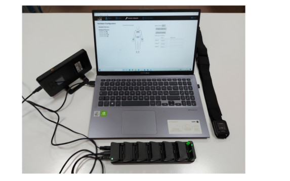
Parkinson's disease is the second most common neurodegenerative disorder in the world. Assumed that gait dysfunctions represent a major motor symptom for the pathology, gait analysis can provide clinicians quantitative information about the rehabilitation outcome of patients. In this scenario, wearable inertial systems for gait analysis can be a valid tool to assess the functional recovery of patients in an automatic and quantitative way, helping clinicians in decision making. Aim of the study is to evaluate the impact of the short-term rehabilitation on gait and balance of patients with Parkinson's disease. A cohort of 12 patients with Idiopathic Parkinson's disease performed a gait analysis session instrumented by a wearable inertial system for gait analysis: Opal System, by APDM Inc., with spatial and temporal parameters being analyzed through a statistic and machine learning approach. Six out of fourteen motion parameters exhibited a statistically significant difference between the measurements at admission and at discharge of the patients, while the machine learning analysis confirmed the separability of the two phases in terms of Accuracy and Area under the Receiving Operating Characteristic Curve. The rehabilitation treatment especially improved the motion parameters related to the gait. The study shows the positive impact on the gait of a short-term rehabilitation in patients with Parkinson's disease and the feasibility of the wearable inertial devices, that are increasingly spreading in clinical practice, to quantitatively assess the gait improvement.
Citation: Leandro Donisi, Giuseppe Cesarelli, Pietro Balbi, Vincenzo Provitera, Bernardo Lanzillo, Armando Coccia, Giovanni D'Addio. Positive impact of short-term gait rehabilitation in Parkinson patients: a combined approach based on statistics and machine learning[J]. Mathematical Biosciences and Engineering, 2021, 18(5): 6995-7009. doi: 10.3934/mbe.2021348
Parkinson's disease is the second most common neurodegenerative disorder in the world. Assumed that gait dysfunctions represent a major motor symptom for the pathology, gait analysis can provide clinicians quantitative information about the rehabilitation outcome of patients. In this scenario, wearable inertial systems for gait analysis can be a valid tool to assess the functional recovery of patients in an automatic and quantitative way, helping clinicians in decision making. Aim of the study is to evaluate the impact of the short-term rehabilitation on gait and balance of patients with Parkinson's disease. A cohort of 12 patients with Idiopathic Parkinson's disease performed a gait analysis session instrumented by a wearable inertial system for gait analysis: Opal System, by APDM Inc., with spatial and temporal parameters being analyzed through a statistic and machine learning approach. Six out of fourteen motion parameters exhibited a statistically significant difference between the measurements at admission and at discharge of the patients, while the machine learning analysis confirmed the separability of the two phases in terms of Accuracy and Area under the Receiving Operating Characteristic Curve. The rehabilitation treatment especially improved the motion parameters related to the gait. The study shows the positive impact on the gait of a short-term rehabilitation in patients with Parkinson's disease and the feasibility of the wearable inertial devices, that are increasingly spreading in clinical practice, to quantitatively assess the gait improvement.

| [1] | J. M. Hausdorff, Gait dynamics in Parkinson's disease: Common and distinct behavior among stride length, gait variability, and fractal-like scaling, Chaos, 19 (2009), 026113. |
| [2] |
L. M. de Lau, M. M. B. Breteler, Epidemiology of Parkinson's disease, Lancet Neurol., 5 (2006), 525-535. doi: 10.1016/S1474-4422(06)70471-9

|
| [3] |
A. Lee, R. M. Gilbert, Epidemiology of Parkinson disease, Neurol. Clin., 34 (2016), 955-965. doi: 10.1016/j.ncl.2016.06.012
|
| [4] | J. M. S. Pearce, Aetiology and natural history of Parkinson's disease, Br. Med. J., 2 (1978), 1664-1666. |
| [5] |
O. Sofuwa, A. Nieuwboer, K. Desloovere, A. M. Willems, F. Chavret, I. Jonkers, Quantitative gait analysis in Parkinson's disease: Comparison with a healthy control group, Arch. Phys. Med. Rehabil., 86 (2005), 1007-1013. doi: 10.1016/j.apmr.2004.08.012
|
| [6] |
M. G. Spillantini, R. A. Crowther, R. Jakes, M. Hasegawa, M. Goedert, α-Synuclein in filamentous inclusions of Lewy bodies from Parkinson's disease and dementia with Lewy bodies, Proc. Natl. Acad. Sci. U.S.A., 95 (1998), 6469-6473. doi: 10.1073/pnas.95.11.6469
|
| [7] |
M. E. Morris, R. Iansek, T. A. Matyas, J. J. Summers, The pathogenesis of gait hypokinesia in Parkinson's disease, Brain, 117 (1994), 1169-1181. doi: 10.1093/brain/117.5.1169
|
| [8] |
N. Giladi, R. Kao, S. Fahn, Freezing phenomenon in patients with parkinsonian syndromes, Mov. Disord., 12 (1997), 302-305. doi: 10.1002/mds.870120307
|
| [9] |
A. Nieuwboer, W. De Weerdt, R. Dom, E. Lesaffre, A frequency and correlation analysis of motor deficits in Parkinson patients, Disabil. Rehabil., 20 (1998), 142-150. doi: 10.3109/09638289809166074
|
| [10] |
J. Verghese, A. LeValley, C. B. Hall, M. J. Katz, A. F. Ambrose, R. B. Lipton, Epidemiology of gait disorders in community-residing older adults, J. Am. Geriatr. Soc., 54 (2006), 255-261. doi: 10.1111/j.1532-5415.2005.00580.x
|
| [11] |
M. E. Morris, Movement disorders in people with parkinson disease: A model for physical therapy, Phys Ther., 80 (2000), 578-597. doi: 10.1093/ptj/80.6.578
|
| [12] | L. I. Golbe, P. A. Ohman-Strickland, A clinical rating scale for progressive supranuclear palsy, Brain, 130 (2007), 1552-1565. |
| [13] | G. D'Addio, L. Donisi, L. Mercogliano, G. Cesarelli, P. Bifulco, M. Cesarelli, Potential biomechanical overload on skeletal muscle structures in students during walk with backpack, in Mediterranean Conference on Medical and Biological Engineering and Computing, Springer, (2019), 262-266. |
| [14] | L. Donisi, A. Coccia, F. Amitrano, L. Mercogliano, G. Cesarelli, G. D'Addio, Backpack influence on kinematic parameters related to Timed Up and Go (TUG) test in school children, in 2020 IEEE International Symposium on Medical Measurements and Applications (MeMeA), IEEE, 2020. |
| [15] |
W. Tao, T. Liu, R. Zheng, H. Feng, Gait analysis using wearable sensors, Sensors, 12 (2012), 2255-2283. doi: 10.3390/s120202255
|
| [16] | L. Donisi, G. Cesarelli, A. Coccia, M. Panigazzi, E. M. Capodaglio, G. D'Addio, Work-related risk assessment according to the revised NIOSH lifting equation: A preliminary study using a wearable inertial sensor and machine learning, Sensors, 21 (2021), 2593. |
| [17] | G. Pagano, G. D'Addio, M. De Campi, L. Donisi, A. Biancardi, M. Cesarelli, Rehabilitation outcome in patients undergone hip or knee replacement surgery using inertial technology for gait analysis, in 2020 IEEE International Symposium on Medical Measurements and Applications (MeMeA), IEEE, 2020. |
| [18] | A. Coccia, B. Lanzillo, L. Donisi, F. Amitrano, G. Cesarelli, G. D'Addio, Repeatability of spatio-temporal gait measurements in Parkinson's disease, in 2020 IEEE International Symposium on Medical Measurements and Applications (MeMeA), IEEE, 2020. |
| [19] | S. Patel, H. Park, P. Bonato, L. Chan, M. Rodgers, A review of wearable sensors and systems with application in rehabilitation, J. Neuroeng. Rehabilitation., 9 (2012). |
| [20] | G. D'Addio, S. Evangelista, L. Donisi, A. Biancardi, E. Andreozzi, G. Pagano, et al., Development of a prototype e-textile sock, in 2019 41st Annual International Conference of the IEEE Engineering in Medicine and Biology Society (EMBC), IEEE, (2019), 1749-1752. |
| [21] | F. Amitrano, L. Donisi, A. Coccia, A. Biancardi, G. Pagano, G. D'Addio, Experimental development and validation of an e-textile sock prototype, in 2020 IEEE International Symposium on Medical Measurements and Applications (MeMeA), IEEE, 2020. |
| [22] | F. Amitrano, A. Coccia, C. Ricciardi, L. Donisi, G. Cesarelli, E. M. Capodaglio, et al., Design and validation of an e-textile-based wearable sock for remote gait and postural assessment, Sensors, 20 (2020). |
| [23] |
X. Xu, R. W. McGorry, L. S. Chou, J. H. Lin, C. C. Chang, Accuracy of the Microsoft Kinect™ for measuring gait parameters during treadmill walking, Gait Posture, 42 (2015), 145-151. doi: 10.1016/j.gaitpost.2015.05.002
|
| [24] |
M. Agmon, C. K. Perry, E. Phelan, G. Demiris, H. Q. Nguyen, A pilot study of Wii Fit exergames to improve balance in older adults, J. Geriatr. Phys. Ther., 34 (2011), 161-167. doi: 10.1519/JPT.0b013e3182191d98
|
| [25] |
M. De Vos, J. Prince, T. Buchanan, J. J. FitzGerald, C.A. Antoniades, Discriminating progressive supranuclear palsy from Parkinson's disease using wearable technology and machine learning, Gait Posture, 77 (2020), 257-263. doi: 10.1016/j.gaitpost.2020.02.007
|
| [26] | M. Mancini, L. King, A. Salarian, L. Holmstrom, J. McNames, F.B. Horak, Mobility lab to assess balance and gait with synchronized body-worn sensors, J. Bioeng. Biomed. Sci., 2012. |
| [27] | L. Donisi, G. Pagano, G. Cesarelli, A. Coccia, F. Amitrano, G. D'Addio, Benchmarking between two wearable inertial systems for gait analysis based on a different sensor placement using several statistical approaches, Measurement, 173 (2021). |
| [28] |
M. Mancini, F. B. Horak, Potential of APDM mobility lab for the monitoring of the progression of Parkinson's disease, Expert Rev. Med. Devices, 13 (2016), 455-462. doi: 10.1586/17434440.2016.1153421
|
| [29] |
N. V. Chawla, K. W. Bowyer, L. O. Hall, W. P. Kegelmeyer, SMOTE: Synthetic minority over-sampling technique, J. Artif. Intell. Res., 16 (2002), 321-357. doi: 10.1613/jair.953
|
| [30] | S. Moon, J. H. Song, V. D. Sharma, K. E. Lyons, R. Pahwa, A. E. Akinwuntan, et al., Classification of Parkinson's disease and essential tremor based on balance and gait characteristics from wearable motion sensors via machine learning techniques: a data-driven approach, J. Neuroeng. Rehabilitation, 17 (2020). |
| [31] | L. Breiman, Random forests, Mach. Learn., 45 (2001), 5-32. |
| [32] |
I. H. Witten, E. Frank, Data mining: practical machine learning tools and techniques with Java implementations, SIGMOD Rec., 31 (2002), 76-77. doi: 10.1145/507338.507355
|
| [33] |
Y. Freund, R. E. Schapire, A decision-theoretic generalization of on-line learning and an application to boosting, J. Comput. Syst. Sci., 55 (1997), 119-139. doi: 10.1006/jcss.1997.1504
|
| [34] | P. Sheng, L. Chen, J. Tian, Learning-based road crack detection using gradient boost decision tree, in 2018 13th IEEE Conference on Industrial Electronics and Applications (ICIEA), IEEE, (2018), 1228-1232. |
| [35] |
T. T. Wong, Performance evaluation of classification algorithms by k-fold and leave-one-out cross validation, Pattern Recognit., 48 (2015), 2839-2846. doi: 10.1016/j.patcog.2015.03.009
|
| [36] | S. Lei, A feature selection method based on information gain and genetic algorithm, in 2012 International Conference on Computer Science and Electronics Engineering, IEEE, 2 (2012), 355-358. |
| [37] | M. Recenti, C. Ricciardi, R. Aubonnet, I. Picone, D. Jacob, H.Á. Svansson, et al., Toward predicting motion sickness using virtual reality and a moving platform assessing brain, muscles, and heart signals, Front. Bioeng. Biotechnol., 9 (2021). |
| [38] |
A. Stanzione, C. Ricciardi, R. Cuocolo, V. Romeo, J. Petrone, M. Sarnataro, et al., MRI radiomics for the prediction of fuhrman grade in clear cell renal cell carcinoma: A machine learning exploratory study, J. Digit. Imaging, 33 (2020), 879-887. doi: 10.1007/s10278-020-00336-y
|
| [39] | D. Scrutinio, C. Ricciardi, L. Donisi, E. Losavio, P. Battista, P. Guida, et al., Machine learning to predict mortality after rehabilitation among patients with severe stroke, Sci. Rep., 10 (2020). |
| [40] | C. Ricciardi, L. Donisi, G. Cesarelli, G. Pagano, A. Coccia, G. D'Addio, Feasibility of machine learning applied to poincaré plot analysis on patients with CHF, in 2020 11th Conference of the European Study Group on Cardiovascular Oscillations (ESGCO), IEEE, 2020. |
| [41] | L. Donisi, C. Ricciardi, G. Cesarelli, G. Pagano, F. Amitrano, G. D'Addio, Machine Learning applied on Poincaré Analyisis to discriminate different cardiac issues, in 2020 11th Conference of the European Study Group on Cardiovascular Oscillations (ESGCO), IEEE, 2020. |
| [42] |
G. Frazzitta, P. Balbi, R. Maestri, G. Bertotti, N. Boveri, G. Pezzoli, The beneficial role of intensive exercise on Parkinson disease progression, Am. J. Phys. Med. Rehabil., 92 (2013), 523-532. doi: 10.1097/PHM.0b013e31828cd254
|
| [43] |
O. Blin, A. M. Ferrandez, J. Pailhous, G. Serratrice, Dopa-sensitive and Dopa-resistant gait parameters in Parkinson's disease, J. Neurol. Sci., 103 (1991), 51-54. doi: 10.1016/0022-510X(91)90283-D
|
| [44] |
M. E. Morris, R. Iansek, T. A. Matyas, J. J. Summers, Stride length regulation in Parkinson's disease: Normalization strategies and underlying mechanisms, Brain, 119 (1996), 551-568. doi: 10.1093/brain/119.2.551
|
| [45] | M. Serrao, G. Chini, G. Caramanico, M. Bartolo, S. F. Castiglia, A. Ranavolo, et al., Prediction of responsiveness of gait variables to rehabilitation training in Parkinson's disease, Front. Neurol., 10 (2019). |
| [46] |
R. Bouça-Machado, F. Pona-Ferreira, N. Gonçalves, M. Leitão, R. Cacho, A. Castro-Caldas, et al., Outcome measures for evaluating the effect of a multidisciplinary intervention on axial symptoms of Parkinson's disease, Front. Neurol., 11 (2020), 328. doi: 10.3389/fneur.2020.00328
|
| [47] | A. Kleiner, M. Galli, M. Gaglione, D. Hildebrand, P. Sale, G. Albertini, et al., The parkinsonian gait spatiotemporal parameters quantified by a single inertial sensor before and after automated mechanical peripheral stimulation treatment, Parkinson's Dis., 2015 (2015). |
| [48] | C. Ricciardi, M. Amboni, C. De Santis, G. Ricciardelli, G. Improta, L. Iuppariello, et al. Classifying different stages of Parkinson's disease through random forests, in Mediterranean Conference on Medical and Biological Engineering and Computing, Springer, Cham, (2020), 1155-1162. |
| [49] | C. Ricciardi, M. Amboni, C. De Santis, G. Improta, G. Volpe, L. Iuppariello, et al., Using gait analysis' parameters to classify Parkinsonism: A data mining approach, Comput. Methods Programs Biomed., 180 (2019). |
| [50] |
E. Abdulhay, N. Arunkumar, K. Narasimhan, E. Vellaiappan, V. Venkatraman, Gait and tremor investigation using machine learning techniques for the diagnosis of Parkinson disease, Future Gener. Comput. Syst, 83 (2018), 366-373. doi: 10.1016/j.future.2018.02.009
|
| [51] |
T. Stuckenschneider, I. Helmich, A. Raabe-Oetker, I. Froböse, B. Feodoroff, Active assistive forced exercise provides long-term improvement to gait velocity and stride length in patients bilaterally affected by Parkinson's disease, Gait Posture, 42 (2015), 485-490. doi: 10.1016/j.gaitpost.2015.08.001
|


Figures(4) / Tables(4)

Leandro Donisi, Giuseppe Cesarelli, Pietro Balbi, Vincenzo Provitera, Bernardo Lanzillo, Armando Coccia, Giovanni D'Addio. Positive impact of short-term gait rehabilitation in Parkinson patients: a combined approach based on statistics and machine learning[J]. Mathematical Biosciences and Engineering, 2021, 18(5): 6995-7009. doi: 10.3934/mbe.2021348


 DownLoad: