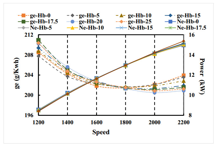
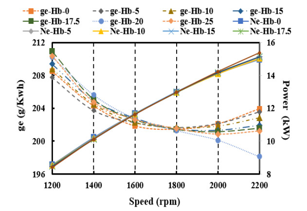
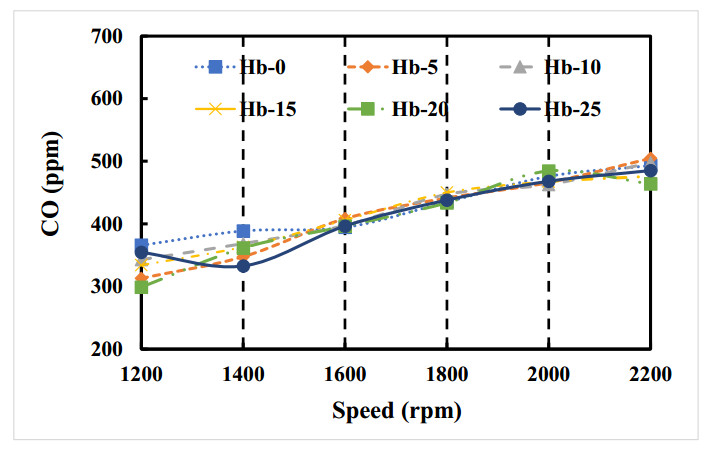
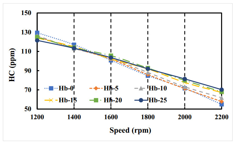
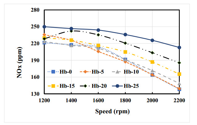
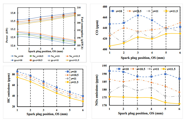
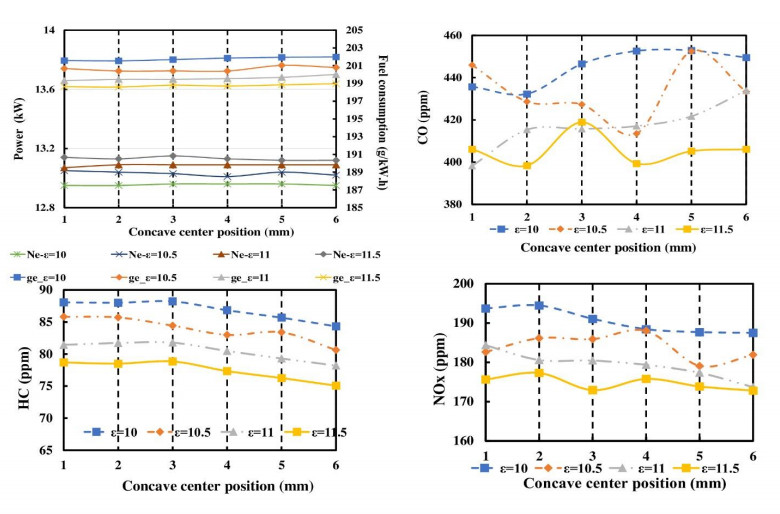
This paper investigates the influence of piston geometry design and spark plug position on the engine performance and emission characteristics at a range of speeds from 1200 rpm to 2200 rpm. Accordingly, the parameters of the indentation depth, the spark plug position, the location of the recess, and the engine's compression ratio are changed and evaluated. The concave center depth improved the mixture of air and fuel, increased power, and reduced fuel consumption. The power can be improved by up to 3% when the piston top recess is 25 mm. In addition, within a limited range, the combustion process and the engine's power and emission characteristics are enhanced when the engine's compression ratio rises. Increasing the depth of the depression on the top of the piston improves fluid flow in the cylinder, resulting in increased power, fuel efficiency, and emissions; however, the improvement between the indentations remains unclear.
Citation: Quoc Dang Tran, Thanh Nhu Nguyen, Vinh Nguyen Duy. Effect of piston geometry design and spark plug position on the engine performance and emission characteristics[J]. AIMS Energy, 2023, 11(1): 156-170. doi: 10.3934/energy.2023009
This paper investigates the influence of piston geometry design and spark plug position on the engine performance and emission characteristics at a range of speeds from 1200 rpm to 2200 rpm. Accordingly, the parameters of the indentation depth, the spark plug position, the location of the recess, and the engine's compression ratio are changed and evaluated. The concave center depth improved the mixture of air and fuel, increased power, and reduced fuel consumption. The power can be improved by up to 3% when the piston top recess is 25 mm. In addition, within a limited range, the combustion process and the engine's power and emission characteristics are enhanced when the engine's compression ratio rises. Increasing the depth of the depression on the top of the piston improves fluid flow in the cylinder, resulting in increased power, fuel efficiency, and emissions; however, the improvement between the indentations remains unclear.

| [1] |
Nguyen Duc K, Nguyen Duy V, Hoang-Dinh L, et al. (2019) Performance and emission characteristics of a port fuel injected, spark ignition engine fueled by compressed natural gas. Sustainable Energy Technol Assess 31: 383–389. https://doi.org/10.1016/j.seta.2018.12.018 doi: 10.1016/j.seta.2018.12.018

|
| [2] |
Jiaqiang E, Pham MH, Deng Y, et al. (2018) Effects of injection timing and injection pressure on performance and exhaust emissions of a common rail diesel engine fueled by various concentrations of fish-oil biodiesel blends. Energy 149: 979–989. https://doi.org/10.1016/j.energy.2018.02.053 doi: 10.1016/j.energy.2018.02.053
|
| [3] |
Dinh T, Nguyen K, Pham T, et al. (2020) Study on performance enhancement and emission reduction of used carburetor motorcycles fueled by flex-fuel gasoline-ethanol blends. J Chinese Inst Eng 43: 1–12. https://doi.org/10.1080/02533839.2020.1751719 doi: 10.1080/02533839.2020.1751719
|
| [4] |
Duc KN, Tien HN, Duy VN (2018) Performance enhancement and emission reduction of used motorcycles using flexible fuel technology. J Energy Inst 91: 145–152. https://doi.org/10.1016/j.joei.2016.09.004 doi: 10.1016/j.joei.2016.09.004
|
| [5] |
Duy VN, Duc KN, Cong DN, et al. (2019) Experimental study on improving performance and emission characteristics of used motorcycle fueled with ethanol by exhaust gas heating transfer system. Energy Sustainable Dev 51: 56–62. https://doi.org/10.1016/j.esd.2019.05.006 doi: 10.1016/j.esd.2019.05.006
|
| [6] |
Cong DN, Duc KN, Nguyen V (2021) The effects of dimethyl ether enriched air (DMEA) on exhaust pollutants and performance characteristics of an old generation diesel engine. Int J Sustainable Eng 14: 1143–1156. https://doi.org/10.1080/19397038.2021.1896590 doi: 10.1080/19397038.2021.1896590
|
| [7] |
Nguyen TD, Tran Anh T, Quang VT, et al. (2020) An experimental evaluation of engine performance and emissions characteristics of a modified direct injection diesel engine operated in RCCI mode. AIMS Energy 8: 1069–1087. https://doi.org/10.3934/energy.2020.6.1069 doi: 10.3934/energy.2020.6.1069
|
| [8] |
Duy V, Duc K, Thanh TN, et al. (2020) Implementation of fuel additive MAZ 100 for performance enhancement of compressed natural gas engine converted from in-used gasoline engine. J Air Waste Manage Assoc 70: 932–943. https://doi.org/10.1080/10962247.2020.1781709 doi: 10.1080/10962247.2020.1781709
|
| [9] |
Shiga S, Ozone S, Machacon HTC, et al. (2002) A study of the combustion and emission characteristics of compressed-natural-gas direct-injection stratified combustion using a rapid-compression-machine. Combust Flame 129: 1–10. https://doi.org/10.1016/S0010-2180(01)00367-4 doi: 10.1016/S0010-2180(01)00367-4
|
| [10] |
Hekkert MP, Hendriks FHJF, Faaij APC, et al. (2005) Natural gas as an alternative to crude oil in automotive fuel chains well-to-wheel analysis and transition strategy development. Energy Policy 33: 579–594. https://doi.org/10.1016/j.enpol.2003.08.018 doi: 10.1016/j.enpol.2003.08.018
|
| [11] | Warguła Ł, Kukla M, Lijewski P, et al. (2020) Impact of compressed natural gas (CNG) fuel systems in small engine wood chippers on exhaust emissions and fuel consumption. Energies 13. https://doi.org/10.3390/en13246709 |
| [12] |
Usman M, Hayat N (2019) Use of CNG and Hi-octane gasoline in SI engine: a comparative study of performance, emission, and lubrication oil deterioration. Energy Sources, Part A Recover Util Environ Eff 1: 1–15. https://doi.org/10.1080/15567036.2019.1683098 doi: 10.1080/15567036.2019.1683098
|
| [13] |
Hagos DA, Ahlgren EO (2018) Well-to-wheel assessment of natural gas vehicles and their fuel supply infrastructures—Perspectives on gas in transport in Denmark. Transp Res Part D Transp Environ 65: 14–35. https://doi.org/10.1016/j.trd.2018.07.018 doi: 10.1016/j.trd.2018.07.018
|
| [14] |
Cho HM, He BQ (2007) Spark ignition natural gas engines—A review. Energy Convers Manage 48: 608–618. https://doi.org/10.1016/j.enconman.2006.05.023 doi: 10.1016/j.enconman.2006.05.023
|
| [15] |
Gnap J, Dočkalik M (2021) Impact of the operation of LNG trucks on the environment. Open Eng 11: 937–947. https://doi.org/10.1515/eng-2021-0096 doi: 10.1515/eng-2021-0096
|
| [16] | Pourkhesalian AM, Shamekhi AH, Salimi F (2010) Alternative fuel and gasoline in an SI engine: A comparative study of performance and emissions characteristics. Fuel 89: 1056–1063. |
| [17] |
Evans RL, Blaszczyk J (1997) A comparative study of the performance and exhaust emissions of a spark ignition engine fuelled by natural gas and gasoline. Proc Inst Mech Eng Part D J Automob Eng 211: 39–47. https://doi.org/10.1016/j.fuel.2009.11.025 doi: 10.1016/j.fuel.2009.11.025
|
| [18] |
Yontar AA, Doğu Y (2018) Experimental and numerical investigation of effects of CNG and gasoline fuels on engine performance and emissions in a dual sequential spark ignition engine. Energy Sources, Part A Recover Util Environ Eff 40: 2176–2192. https://doi.org/10.1080/15567036.2018.1495783 doi: 10.1080/15567036.2018.1495783
|
| [19] |
Jahirul MI, Masjuki HH, Saidur R, et al. (2010) Comparative engine performance and emission analysis of CNG and gasoline in a retrofitted car engine. Appl Therm Eng 30: 2219–2226. https://doi.org/10.1016/j.applthermaleng.2010.05.037 doi: 10.1016/j.applthermaleng.2010.05.037
|
| [20] |
Yontar AA, Doğu Y (2018) Investigation of the effects of gasoline and CNG fuels on a dual sequential ignition engine at low and high load conditions. Fuel 232: 114–123. https://doi.org/10.1016/j.fuel.2018.05.156 doi: 10.1016/j.fuel.2018.05.156
|
Figures(9) / Tables(3)

Quoc Dang Tran, Thanh Nhu Nguyen, Vinh Nguyen Duy. Effect of piston geometry design and spark plug position on the engine performance and emission characteristics[J]. AIMS Energy, 2023, 11(1): 156-170. doi: 10.3934/energy.2023009


 DownLoad: