Review Topical Sections

Contributions of immune cell populations in the maintenance, progression, and therapeutic modalities of glioma

  • Received: 07 February 2018 Accepted: 19 March 2018 Published: 21 March 2018
  • Immunotherapies are becoming a promising strategy for malignant disease. Selectively directing host immune responses to target cancerous tissue is a milestone of human health care. The roles of the innate and adaptive immune systems in both cancer progression and elimination are now being realized. Defining the immune cell environment and identifying the contributions of each sub-population of these cells has lead to an understanding of the immunotherapeutic processes, and demonstrated the potential of the immune system to drive cancer shrinkage and sustained immunity against disease. Poorly treated diseases, such as high-grade glioma, suffer from lack of therapeutic efficacy and rapid progression. Immunotherapeutic success in other solid malignancies, such as melanoma, now provides the principals for which this treatment paradigm can be adapted for primary brain cancers. The central nervous system is complex, and relative contributions of immune sub-populations to high grade glioma progression are not fully characterized. Here, we summarize recent research in both animal and humans which add to the knowledge base of how innate and adaptive immune cells contribute to glioma progression, and outline work which has demonstrated their potential to elicit anti-tumorigenic responses. Additionally, we highlight Neuropilin 1, a cell surface receptor protein, describe its signaling functions in the context of immunity, and point to its potential to slow glioma progression.

    Citation: Michael D. Caponegro, Jeremy Tetsuo Miyauchi, Stella E. Tsirka. Contributions of immune cell populations in the maintenance, progression, and therapeutic modalities of glioma[J]. AIMS Allergy and Immunology, 2018, 2(1): 24-44. doi: 10.3934/Allergy.2018.1.24

    Related Papers:

    [1] Xingyou Yao . EWM-based design method for distortional buckling of cold-formed thin-walled lipped channel sections with holes. Mathematical Biosciences and Engineering, 2022, 19(1): 972-996. doi: 10.3934/mbe.2022045
    [2] Zhizhou Ma, Yujun Qi, Weiqing Liu . A comparative study of pull-out performance of bolted joints in pultruded FRP with drilled holes or punched holes. Mathematical Biosciences and Engineering, 2019, 16(5): 4213-4228. doi: 10.3934/mbe.2019210
    [3] Panagiotes A. Voltairas, Antonios Charalambopoulos, Dimitrios I. Fotiadis, Lambros K. Michalis . A quasi-lumped model for the peripheral distortion of the arterial pulse. Mathematical Biosciences and Engineering, 2012, 9(1): 175-198. doi: 10.3934/mbe.2012.9.175
    [4] Dingwei Tan, Yuliang Lu, Xuehu Yan, Lintao Liu, Longlong Li . High capacity reversible data hiding in MP3 based on Huffman table transformation. Mathematical Biosciences and Engineering, 2019, 16(4): 3183-3194. doi: 10.3934/mbe.2019158
    [5] Yan Li, Junwei Wang, Shuangkui Ge, Xiangyang Luo, Bo Wang . A reversible database watermarking method with low distortion. Mathematical Biosciences and Engineering, 2019, 16(5): 4053-4068. doi: 10.3934/mbe.2019200
    [6] Bang Dou, Fangfang Zhang, Ming Ni, Yahui Dai, Zhiyuan Wang, Tao Qin, Wenqian Ma, Wei Zhu, Jiong Mei . Biomechanical and finite element study of drilling sites for benign lesions in femoral head and neck with curettage, bone-grafting and internal fixation. Mathematical Biosciences and Engineering, 2019, 16(6): 7808-7828. doi: 10.3934/mbe.2019392
    [7] Xiaoyu Du, Yijun Zhou, Lingzhen Li, Cecilia Persson, Stephen J. Ferguson . The porous cantilever beam as a model for spinal implants: Experimental, analytical and finite element analysis of dynamic properties. Mathematical Biosciences and Engineering, 2023, 20(4): 6273-6293. doi: 10.3934/mbe.2023270
    [8] Matthias Ngwa, Ephraim Agyingi . A mathematical model of the compression of a spinal disc. Mathematical Biosciences and Engineering, 2011, 8(4): 1061-1083. doi: 10.3934/mbe.2011.8.1061
    [9] Cong Wang, Chang Liu, Mengliang Liao, Qi Yang . An enhanced diagnosis method for weak fault features of bearing acoustic emission signal based on compressed sensing. Mathematical Biosciences and Engineering, 2021, 18(2): 1670-1688. doi: 10.3934/mbe.2021086
    [10] Yong Tian, Tian Zhang, Qingchao Zhang, Yong Li, Zhaodong Wang . Feature fusion–based preprocessing for steel plate surface defect recognition. Mathematical Biosciences and Engineering, 2020, 17(5): 5672-5685. doi: 10.3934/mbe.2020305
  • Immunotherapies are becoming a promising strategy for malignant disease. Selectively directing host immune responses to target cancerous tissue is a milestone of human health care. The roles of the innate and adaptive immune systems in both cancer progression and elimination are now being realized. Defining the immune cell environment and identifying the contributions of each sub-population of these cells has lead to an understanding of the immunotherapeutic processes, and demonstrated the potential of the immune system to drive cancer shrinkage and sustained immunity against disease. Poorly treated diseases, such as high-grade glioma, suffer from lack of therapeutic efficacy and rapid progression. Immunotherapeutic success in other solid malignancies, such as melanoma, now provides the principals for which this treatment paradigm can be adapted for primary brain cancers. The central nervous system is complex, and relative contributions of immune sub-populations to high grade glioma progression are not fully characterized. Here, we summarize recent research in both animal and humans which add to the knowledge base of how innate and adaptive immune cells contribute to glioma progression, and outline work which has demonstrated their potential to elicit anti-tumorigenic responses. Additionally, we highlight Neuropilin 1, a cell surface receptor protein, describe its signaling functions in the context of immunity, and point to its potential to slow glioma progression.


    The CFS lipped channel sections have been widely used in buildings as walls, floors, and ceilings due to their high strength-to-weight ratio and ease of construction. However, the holes often appear in the web because of the installation of electrical, plumbing, and heating conduits for such lipped channel sections. The occurrence of holes in the web would decrease the cross-section area, stiffness and the constraint for the flange, which makes such sections prone to be distortional buckling.

    In the literature, the distortional buckling of CFS members has been investigated by most researchers. Based on the studies conducted by Schafer et al. [1,2] and Yao et al. [3,4], the design methods of distortional buckling were given in the AISI 100-2016 [5] and GB50018 [6], respectively. Meanwhile, some significant work has been reported on the reduction in strength of channel sections having openings covering web crippling by Uzzaman et al. [7,8,9,10] and Lian et al. [11,12,13,14], shear by Pham [15], Pham et al. [16], Keerthan et al. [17,18], and Pham et al [16], the bending of beam by Moen et al. [20] and Zhao et al. [21], and the deep learning-based prediction by using Deep Belief Network by Fang et al. [22,23].

    Recently, Chen et al. [24,25,26] reported experimental and numerical studies on the axial strength of single channels and back-to-back channels with edge-stiffened holes and found that the axial strength of channels with edge-stiffened holes was greater than those of plain channels. Meanwhile, some other work has been reported on the strength of channel sections having edge-stiffened hole covering web crippling by Uzzaman et al. [27,28] and moment capacity by Chen et al. [29].

    In the literature, limited work has been reported on distortional buckling of CFS channels with holes in the web. The compression tests of 24 short and intermediate CFS lipped channel columns with and without slotted web holes showed that the presence of slotted hole caused a slight decrease in the ultimate capacity [30]. For lipped channel columns with web stiffener, numerical and experimental studies were carried out to analysis the effects of holes on the failure mode and load-carrying capacity by Yao and Wu [31]. The results demonstrated that the holes led the change of bucking mode and decreased the ultimate strength. The effects of holes on the buckling behavior of CFS channels under axial compression were studied by Macdonald et al. [32,33], and it was found that the ultimate failure load of the channels under compression varied greatly with the presence of holes. Zheng and Yu [34] reported the distortional buckling behavior of the CFS channel with web openings by using ANSYS finite element software, and the influence of the transverse and longitudinal hole spacing, the hole size, and the shape of the hole on the distortional buckling.

    In order to develop the design method of effective width method and direct strength method for the axially-compressed member with holes, the calculated method of buckling coefficient and elastic buckling capacity for the member with holes has been studied by some researchers. The equivalent modulus method is used to calculate the elastic buckling stress of CFS members with slotted holes by Zhou and Yu [35]. According to finite element analysis, the modified formula of the distortional buckling coefficient for axially-compressed member with circular hole was given by Yao et al. [36]. The simplified methods to predict the local, distortional, and global critical elastic buckling loads of CFS columns with holes were developed based on theoretical and FE analysis [37]. Based on experiments and theoretical analysis, the modified direct strength methods were proposed by Moen and Schafer [38] and Yao and Rasmussen [39] for calculating the distortional buckling capacity of CFS members with web openings under axial compression. In terms of the design standards, the American Iron and Steel Institute (AISI) [5] do not provide sufficient effective width design rules for determining the distortional buckling strength of CFS channels with holes because the reduced effective width method is only suitable to members with relatively small holes in these codes. The direct strength method is given in AISI for determining distortional buckling strength of CFS channels with holes, but the elastic buckling capacity of members with holes need to be calculated by using finite element method or complicated formula. Meanwhile, there is no design provision about distortional buckling for the perforated members in the Chinese code [6].

    As mentioned previously literatures, some works considered the distortional buckling behavior and design method of the CFS channels with holes have been reported. Nevertheless, limited work considered the distortional buckling has been reported on columns with large holes under axial compression by using effective width method. Thus, this paper reports 44 new distortional buckling experiments on the axial strength of CFS lipped channels with rectangular holes in the web. A nonlinear elasto-plastic FE model was then developed and validated against the test results in terms of ultimate strength and buckling modes. Using the validated FE model, a parametric study involving 16 models was conducted to investigate the effects of sections, hole size, and number of holes on the axial strength of such columns. The proven FEM was used to develop the distortional buckling coefficient equation of CFS lipped channel section under axial compression considering the effect of holes. Finally, the prediction method of ultimate strength of CFS lipped channels with holes in the web considering distortional buckling was proposed and the design strengths were compared against both the test and FEA results.

    This test employed 44 CFS lipped channel sections under axial compression. There were 8 nonperforated members and 36 members with rectangular holes. The definitions of geometric parameters of specimen and the location and spacing of holes are illustrated in Figure 1. Four cross-sections were selected. The nominal thicknesses of the specimens are 0.8 and 1.0 mm. The heights of the rectangular holes are 0.2, 0.4, and 0.6 to the web depth. The ratio of length-to-width (Lh/Hh) of rectangular hole is equal to 2. The length of specimens is 500 and 1000 mm. The hole spacings are 300 mm for members with two rectangular holes. The labeling rule of all specimens is defined in Figure 2. For example, the label "C8008-05-RH21-1" defines the specimen as follows: C indicates the section is a lip channel section column; 8008 means that the nominal height of the web and the nominal thickness of section are 80 and 0.8 mm, respectively; RH21 represents that the section has a rectangular hole and the ratio of the height of the rectangular hole to the height of the web is 0.2; 1 represents the sequence number of the same specimens. The nominal and measured dimensions of all specimens are tabulated in Table 1.

    Figure 1.  Section dimensions and holes size of CFS lipped channel columns.
    Figure 2.  Specimen labeling.
    Table 1.  Nominal and measured sectional dimensions.
    Specimen Nominal sectional dimension Measured sectional dimension initial imperfection Δmax/mm
    L/mm h/mm b/mm a/mm t/mm L/mm h/mm b1/mm b2/mm a1/mm a2/mm
    C8008-05-NH-1 500 80 60 10 0.80 499.45 76.61 58.89 59.19 10.13 10.49 1.251
    C8008-05-NH-2 499.55 78.77 58.93 58.88 10.17 9.85 1.124
    C8008-05-RH21-1 499.40 79.13 58.82 59.87 10.05 10.02 0.876
    C8008-05-RH21-2 499.35 77.11 58.72 60.14 9.22 9.79 0.752
    C8008-05-RH41-1 499.15 77.20 60.11 58.88 9.59 9.42 0.641
    C8008-05-RH41-2 499.50 79.18 59.58 59.38 10.07 9.95 0.521
    C8008-05-RH61-1 499.25 78.35 59.94 59.88 9.54 9.52 0.981
    C8008-05-RH61-2 499.35 77.69 60.26 59.29 10.32 9.46 1.141
    C10010-05-NH-1 500 100 90 10 1.00 474.15 99.25 90.05 89.19 9.04 8.83 0.825
    C10010-05-NH-2 499.55 97.97 89.13 89.14 9.56 9.98 1.028
    C10010-05-RH21-1 499.40 97.70 90.04 89.27 9.65 9.23 1.254
    C10010-05-RH21-2 499.45 99.27 89.62 89.61 9.58 9.16 1.158
    C10010-05-RH41-1 499.50 99.37 89.58 90.02 9.32 9.24 1.345
    C10010-05-RH41-2 499.20 98.18 89.23 88.71 9.78 9.43 1.429
    C10010-05-RH61-1 499.40 96.75 89.80 89.81 9.34 9.39 0.988
    C10010-05-RH61-2 499.20 98.21 89.44 88.78 9.64 9.49 1.024
    C8008-10-NH-1 1000 80 60 10 0.8 1000.00 79.31 58.98 58.78 9.87 10.41 0.812
    C8008-10-NH-2 1000.20 79.57 58.89 59.06 10.26 9.76 0.988
    C8008-10-RH21-1 999.80 79.23 59.40 59.61 10.03 9.91 0.841
    C8008-10-RH21-2 999.95 78.87 59.60 59.66 9.66 10.11 0.754
    C8008-10-RH41-1 1000.00 79.64 59.57 59.09 9.47 9.56 0.684
    C8008-10-RH41-2 1000.10 79.36 59.52 59.39 9.98 9.25 0.751
    C8008-10-RH61-1 999.90 78.50 60.12 59.54 9.80 9.60 1.042
    C8008-10-RH61-2 1000.10 78.58 59.78 59.36 9.81 9.93 0.985
    C8008-10-RH22-1 999.05 78.68 59.93 59.41 9.83 9.61 1.451
    C8008-10-RH22-2 999.95 79.23 59.58 58.90 10.19 9.68 1.345
    C8008-10-RH42-1 999.85 79.55 58.79 59.70 9.51 10.10 1.231
    C8008-10-RH42-2 1000.00 78.78 60.17 59.49 9.65 9.50 1.012
    C8008-10-RH62-1 999.70 79.38 59.43 59.39 9.69 9.80 0.984
    C8008-10-RH62-2 999.95 78.67 58.99 57.80 11.50 10.37 0.756
    C10010-10-NH-1 1000 100 90 10 1 999.00 98.97 88.95 88.44 9.29 9.83 0.852
    C10010-10-NH-2 999.00 98.45 89.72 89.08 8.75 9.76 0.734
    C10010-10-RH21-1 1000.00 99.83 87.83 89.02 8.92 9.38 1.102
    C10010-10-RH21-2 999.50 99.73 88.45 89.15 9.02 9.34 1.034
    C10010-10-RH41-1 999.50 99.56 89.18 89.35 8.79 9.19 0.614
    C10010-10-RH41-2 1000.00 99.85 88.67 89.06 8.87 9.09 0.785
    C10010-10-RH61-1 1001.00 99.13 89.35 89.04 9.37 9.26 0.635
    C10010-10-RH61-2 1000.25 98.89 88.85 89.32 9.76 9.35 0.564
    C10010-10-RH22-1 1001.00 99.34 88.50 87.93 9.51 9.11 0.645
    C10010-10-RH22-2 1000.00 99.58 88.93 88.26 9.23 10.09 0.451
    C10010-10-RH42-1 999.90 99.18 89.34 88.51 10.15 9.29 0.845
    C10010-10-RH42-2 1000.00 98.92 88.75 88.74 9.23 9.23 0.684
    C10010-10-RH62-1 1000.00 98.41 89.34 89.01 9.91 10.06 0.945
    C10010-10-RH62-2 1000.00 98.50 89.65 89.11 9.89 9.27 0.863

     | Show Table
    DownLoad: CSV

    Steel sheets of grade LQ550 with two kinds of thicknesses were selected to manufacture the specimens. 3 tensile coupon tests of steel sheets with different thicknesses were conducted to determine the material properties based on Chinese specification "Tensile tests of metallic materials Part 1: test methods at room temperature" (GB/T228.1-2010) [19]. The stress-strain curves of coupons for every kind of steel plates are shown in Figure 3. The measured average material properties including the static 0.2% proof stress (f0.2), initial Young's modulus (E), ultimate strength (fu), and ultimate strain (εu) are listed in Table 2.

    Figure 3.  Stress-strain curve of coupon test.
    Table 2.  Mean value of material properties.
    t/mm f0.2/MPa fu/MPa E/MPa εu/%
    0.80 600 602 2.16 × 10⁵ 7.19
    1.00 620 634 2.15 × 10⁵ 8.92

     | Show Table
    DownLoad: CSV

    The initial geometric imperfection resulted from forming and transportation has a great influence on the buckling behavior of CFS members. So the initial imperfections of all specimens along the longitudinal direction were measured before test. The interval of longitudinal location measured was 150 mm. The measuring locations of cross-section are illustrated in Figure 4, including the initial local imperfection calculated by locations 1 and 3 and the initial distortional imperfection predicted by locations 2 and 4. The initial local and distortional geometric imperfections of Section C8008 and Section C10010 are depicted in Figure 5. The initial imperfections indicated that the imperfections of the CFS lipped channel columns had no obvious laws along the longitudinal direction. The maximum initial geometric imperfection magnitudes (Δmax) for all specimens are listed in Table 2.

    Figure 4.  Measure locations of initial geometric imperfections.
    Figure 5.  Measured initial geometric imperfections of specimens.

    The reaction frame system and a 500 kN hydraulic jack were used to apply axial compression load on all specimens as shown in Figure 6. The upper actuator and lower pedestal were fitted with 250 mm × 200 mm × 8 mm thick steel platen ground flat and parallel. The column specimens put directly on the steel platen as they were compressed. Friction between the column ends and the steel platens were the only lateral forces that restrained the column cross-section under load. A load cell measured the applied compression force on each specimen. The displacement transducers and strain gauges were adopted to capture the displacement, deformation, and stress of the specimens during the loading process as illustrated in Figure 7. For specimens without hole, four position transducers (Figure 7(a)) were used to record the lateral deformations and four strain gauges (Figure 7(b)) were arranged to measure the stress of web. These instrumentations are set at the mid-height of the stud column. At the mid-height of all specimens with hole, four position transducers (Figure 7(c)) and four strain gauges (Figure 7(d)) were positioned. At the web about 50 mm higher the mid-height of specimens with hole, Three position transducers and four strain gauges were employed as depicted in Figure 7(e), (f). A position transducer was set at the upper end plate of the specimens to measure the vertical displacement under axial load for all specimens.

    Figure 6.  Test setup.
    Figure 7.  Instrumentation arrangement.

    The buckling failure modes of 44 axial compression specimens are shown in Table 3, where L represents local buckling, D represents distorted buckling. Pt, Pa, Pc are the test result, finite element analysis result, and calculated result by using proposed method, respectively.

    Table 3.  Comparison on buckling modes and load-carrying capacities for specimens.
    Specimen Test buckling mode FEA buckling mode Pt/KN Reduction in capacity /% Pa/KN Pc Pt/Pa Pt/Pc
    C8008-05-NH-1 L + D L + D 34.38 35.44 34.04 0.97 1.01
    C8008-05-NH-2 L + D L + D 35.97 36.33 34.17 0.99 1.05
    C8008-05-RH21-1 L + D L + D 34.55 1.78 34.9 32.48 0.99 1.06
    C8008-05-RH21-2 L + D L + D 34.4 2.2 34.77 32.06 0.99 1.07
    C8008-05-RH41-1 L + D L + D 33.3 5.33 33.64 30.97 0.99 1.08
    C8008-05-RH41-2 L + D L + D 33.91 3.6 34.1 30.29 0.99 1.12
    C8008-05-RH61-1 L + D L + D 29.91 14.97 31.82 29.01 0.94 1.03
    C8008-05-RH61-2 L + D L + D 29.45 16.28 31.1 28.97 0.95 1.02
    C10010-05-NH-1 D D 52.31 53.7 49.98 0.97 1.05
    C10010-05-NH-2 D D 52.48 54.67 49.86 0.96 1.05
    C10010-05-RH21-1 D D 51.95 0.85 53.01 48.83 0.98 1.06
    C10010-05-RH21-2 D D 51.48 1.75 52.53 48.91 0.98 1.05
    C10010-05-RH41-1 D D 51.1 2.48 53.23 48.03 0.96 1.06
    C10010-05-RH41-2 D D 50.22 4.16 51.77 48.21 0.97 1.04
    C10010-05-RH61-1 D D 46.19 11.85 49.14 42.96 0.94 1.08
    C10010-05-RH61-2 D D 44.12 15.8 45.96 43.24 0.96 1.02
    C8008-10-NH-1 L + D L + D 27.52 28.3 26.42 0.97 1.04
    C8008-10-NH-2 L + D L + D 27.85 28.3 26.4 0.98 1.05
    C8008-10-RH21-1 L + D L + D 27.5 0.6 28 25.87 0.98 1.06
    C8008-10-RH21-2 L + D L + D 27.74 -0.2 27.91 25.83 0.99 1.07
    C8008-10-RH41-1 L + D L + D 26.94 2.6 26.28 24.06 1.03 1.12
    C8008-10-RH41-2 L + D L + D 26.33 4.8 25.99 24.15 1.01 1.09
    C8008-10-RH61-1 L + D L + D 23.8 13.9 24.2 22.73 0.98 1.05
    C8008-10-RH61-2 L + D L + D 23.88 13.7 23.99 22.89 1.00 1.04
    C8008-10-RH22-1 L + D L + D 27.6 0.25 27.25 25.53 1.01 1.08
    C8008-10-RH22-2 L + D L + D -- -- 27.79 25.69 -- --
    C8008-10-RH42-1 L + D L + D 26.52 4.2 26.05 23.91 1.02 1.11
    C8008-10-RH42-2 L + D L + D -- -- 26.5 23.6 -- --
    C8008-10-RH62-1 L + D L + D 23.5 15.1 24.02 22.45 0.98 1.05
    C8008-10-RH62-2 L + D L + D -- -- 23.42 22.66 -- --
    C10010-10-NH-1 L + D L + D 41.7 41.29 41.31 1.01 1.01
    C10010-10-NH-2 L + D L + D 39.6 40.58 40.73 0.98 0.97
    C10010-10-RH21-1 L + D L + D 40.1 1.3 40.62 39.64 0.99 1.01
    C10010-10-RH21-2 L + D L + D 40.95 -0.74 40.65 39.68 1.01 1.03
    C10010-10-RH41-1 L + D L + D 39.38 3.1 39.9 36.79 0.99 1.07
    C10010-10-RH41-2 L + D L + D 39.4 3.1 39.26 36.71 1.00 1.07
    C10010-10-RH61-1 L + D L + D 37.3 8.2 36.51 35.52 1.02 1.05
    C10010-10-RH61-2 L + D L + D 37.66 7.4 36.1 35.83 1.04 1.05
    C10010-10-RH22-1 L + D L + D 40.25 0.98 39.99 39.55 1.01 1.02
    C10010-10-RH22-2 L + D L + D -- -- 40.52 40.15 -- --
    C10010-10-RH42-1 L + D L + D 38.45 5.4 38.88 37.16 0.99 1.03
    C10010-10-RH42-2 L + D L + D 38.7 4.8 38.46 37.52 1.01 1.03
    C10010-10-RH62-1 L + D L + D 36.8 9.5 36.36 36.08 1.01 1.02
    C10010-10-RH62-2 L + D L + D 37.05 8.9 36.87 35.94 1.00 1.03
    Average 0.99 1.05
    Standard deviation 0.0005 0.0009
    Variable coefficient 0.023 0.029

     | Show Table
    DownLoad: CSV

    It can be found from Table 3, the local buckling occurred firstly for the Section C8008 with the length of 500 mm (Figure 8(a)). With the increase of load, the distortional buckling appeared sequentially (Figure 8(b)). Finally, the specimens failed with the interaction of local and distortional buckling (Figure 8(c)). For Section C10010 with the length of 500 mm, the distortional buckling occurred firstly (Figure 9(a)). Then the deformation of distortional buckling was more and more obvious with the increase of load (Figure 9(b)). The specimens failed with distortional buckling (Figure 9(c)). For Sections C10010 and C8008 with the length of 1000 mm, the local buckling occurred at the web firstly (Figure 10(a)). Then the distortional buckling appeared with the increasing of load (Figure 10(b)). Finally the specimens suffered with interaction of local and distortional buckling (Figure 10(c)).

    Figure 8.  Section C8008 with the length of 500 mm.
    Figure 9.  Section C10010 with the length of 500 mm.
    Figure 10.  Sections C10010 and C8008 with the length of 1000 mm.

    The comparison on load-strain curves at the plate adjacent to hole (Point 4) for specimen C10010 with the length of 1000 mm and different hole sizes is shown in Figure 11. It can be seen from Figure 11, the strain gradually increases with the increase of the hole size, which indicates that the stress concentration is more obvious with the increase of hole size.

    Figure 11.  Load-strain curves for Section C10010 with different hole sizes.

    Figure 12 shows the load-strain curves of the specimen C10010-10-RH21-1 at two cross-sections. For the cross-section which is higher than middle cross-section, it can be seen from Figure 12(a), the strains of all points increases linearly before the load of the specimen reaches 24 kN. The strain changes abruptly after the load exceeds 24 kN which indicates that the local buckling occurs for the web. For the middle cross-section, it can be seen from Figure 12(b), the strain changes abruptly when the load reaches 15 kN which indicates the local buckling occurs at the plate adjacent to hole. The above comparison shows that the presence of hole lets the local buckling occur early.

    Figure 12.  Load-strain curve of specimen C10010-10-RH21-1.

    The comparisons on load-strain curves between the plate adjacent to hole (Point 4) and the position higher 100 mm along the longitudinal direction (Point 1) for the Section C10010 with the length of 1000 mm and different hole sizes are shown in Figure 13. It can be seen from Figure 13, the strain of the plate adjacent to hole is larger than that of the position higher 100 mm along the longitudinal direction because of the stress concentration resulted from the hole. Larger the hole size is, larger the stress concentration is.

    Figure 13.  Comparison on load-strain curves between the plate adjacent to hole and the position higher 100 mm along the longitudinal direction for section C10010-10.

    The load-carrying capacities of all specimens are shown in Table 3. As can be seen from Table 3, the load-carrying capacities for Sections C8008 and C10010 with the length of 500 mm and hole size Hh/h of 0.2, 0.4 and 0.6 decrease by 2.2, 6.33, 16.28% and 1.75, 4.16, 15.8% compared with the specimens without hole, respectively. The load-carrying capacities for Sections C8008 and C10010 with the length of 1000 mm and hole size Hh/h of 0.2, 0.4 and 0.6 decrease by 0.6, 4.8, 13.9% and 1.3, 3.1, 8.2% compared with the specimens without hole, respectively. It indicates that the load-carrying capacity of the specimen decreases obviously with the increase of the hole size. It indicates that the load-carrying capacity of the specimen decreases obviously with the increase of the hole size. For the specimens with the length of 100 mm and two rectangular holes, the same conclusion can be obtained.

    Figure 14 shows the load-axial displacement curves of the Section C10010 with the length of 1000 mm for different hole sizes. It can be seen from Figure 13 that the load-carrying capacity and the ductility of the specimen decrease with the increasing of the hole size.

    Figure 14.  Load-displacement curves for specimens with section C10010-10.

    The finite element program ABAQUS [20] was used to simulate the distortional buckling modes and behavior of the specimens and conduct a further parametric analysis on the CFS lipped channel axially-compressed columns with rectangular holes. The finite element model is shown in Figure 15. The S4R shell element was selected for modeling column and the analytical rigid body element was used for modeling the upper and lower end steel plates of the specimens. The dimensions of the cross sections measured before the tests were used in the FEM. The mesh size of 5 mm × 5 mm was selected to model specimens. The ideal elasto-plastic model based on the material properties obtained from the coupon tests shown in Table 2 was used in FEM. The end constraint conditions of the test plate were all fixed, by constraining the five degrees of freedom of the reference point RP1 at the upper end plate (2 translation degrees of freedom and 3 rotational degree of freedom, releasing UZ degrees of freedom to control displacement) and the six degrees of freedom of the reference point RP2 at the lower end plate. In fact, the fixed end constraint conditions developed in the paper had a few different with the test because a litter movement or rotation can be observed at the failure stage for the specimen ends. But the effect of this error on the buckling mode and the load carrying capacity can be ignored in the finite element analysis. The measured dimensions of specimens (see in Table 1) were all included in the models. The analysis procedure included two phases: Firstly, an eigenvalue buckling analysis was performed to find the most probable elastic buckling mode of the specimen. The measured maximum magnitude of the initial geometric imperfections shown in Table 1 was applied to the first eigen-mode to produce the geometric imperfection of FEM. Secondly, nonlinear analysis considering both material nonlinear and geometric nonlinear was carried out by using the arc-length method to analyze the failure modes and ultimate load-carrying capacity of the specimen.

    Figure 15.  Finite element model.

    The buckling failure mode and load-carrying capacities of all specimens obtained from the finite element analysis are shown in Table 3. It can be seen from Table 3 that the buckling modes of the specimens obtained from the finite element analysis are consistent with the experimental buckling mode. The maximum error of the load-carrying capacity between the test and the finite element analysis results is 6%. The mean value and the corresponding coefficient of variation of ratio of the test result and the finite element analysis result are 0.99 and 0.023, respectively. The comparison on load-axial displacement curve and buckling mode of the finite element analysis and test for the specimen C10010-10-RH61-1 are shown in Figures 16 and 17, respectively. By the above-mentioned comparison, the load-carrying capacities, the failure modes, and load-displacement curves obtained from FEA show good agreement with the test results. Therefore, the FEM developed in this study for the axially-compressed members with rectangular hole in the web has been well validated with the tests.

    Figure 16.  Comparison on load-displacement curves of specimens.
    Figure 17.  Comparison on buckling mode of specimens.

    The proven finite element model was used to analysis on the buckling behavior and ultimate load-carrying capacity of Sections SS89 and SS7510 with different hole sizes and lengths which are widely used in engineering. The section dimensions of the columns with holes, the buckling modes and the ultimate load-carrying capacities obtained from the finite element analysis were shown in Table 4, and G represents the overall buckling.

    Table 4.  Finite element analysis for axially-compressed columns with holes in the web.
    h/mm b/mm a/mm t/mm fy/MPa L/mm Hh/mm Lh/mm The number of holes Hole spacing S/mm Buckling mode Pa/kN Pc/kN Pa/Pc
    89 41 13 1 280 1000 0 0 0 - L 36.5 34.2 1.07
    89 41 13 1 280 1000 26.7 26.7 1 - L + D 35.8 33.4 1.07
    89 41 13 1 280 1000 44.5 44.5 1 - L + D 33.9 31 1.09
    89 41 13 1 280 1500 62.3 62.3 1 - L+ D 29.8 27.8 1.07
    89 41 13 1 280 1500 0 0 0 - L + G 34.3 31.4 1.09
    89 41 13 1 280 1500 26.7 26.7 3 500 L + G 33.2 30.8 1.08
    89 41 13 1 280 1500 44.5 44.5 3 500 L+D+G 30.8 28.4 1.08
    89 41 13 1 280 1500 62.3 62.3 3 500 L+D+G 27.5 25.2 1.09
    75 40 8 1 550 1000 0 0 0 - L + D 43.2 41 1.05
    75 40 8 1 550 1000 22.5 22.5 1 - L + D 42.3 40.5 1.04
    75 40 8 1 550 1000 37.5 37.5 1 - L + D 39.7 37.8 1.05
    75 40 8 1 550 1500 52.5 52.5 1 - L+D+G 36.1 33.5 1.08
    75 40 8 1 550 1500 0 0 0 - L+D+G 35.3 32.6 1.08
    75 40 8 1 550 1500 22.5 22.5 3 500 L+D+G 34.4 32.2 1.07
    75 40 8 1 550 1500 37.5 37.5 3 500 L+D+G 30.9 28.5 1.08
    75 40 8 1 550 1500 52.5 52.5 3 500 L+D+G 27.3 25.1 1.09
    Mean value 1.07
    Standard deviation 0.0002
    Coefficient of variable 0.014

     | Show Table
    DownLoad: CSV

    It can be seen from Table 4 that the ultimate load-carrying capacity gradually decreases with the increase of the hole size. Larger the hole size is, lower the ultimate load-carrying capacity is. For example, the ultimate load-carrying capacity of the Section SS89 with the length of 1000 mm and the hole size Hh/h of 0.7 decreases by 18% compared with that of the Section SS89 with the length of 1000 mm without hole. At the same time, it can be found that the buckling mode of the members with large holes may change from interaction of local and distortional buckling to interaction of local, distortional, and overall buckling due to the reduction of the rotational constraint of the web to the flange and the bending stiffness.

    The load-carrying capacity of the axially-compressed member with rectangular holes can be calculated by using effective width method in Chinese code GB50018-2002. The calculation formula is shown in Eq (1):

    $ N = \varphi {A_e}f $ (1)

    where, φ is the overall buckling coefficient of the axially-compressed member; Ae is the effective area of the cross section, which should be calculated by the effective width of the cross section be. The effective width of the web can be predicted according to the suggested method in reference [21]. The effective width of flange is calculated by using the Eq (2), and the buckling coefficient takes into account the influence of the hole. For single rectangular hole and multi-rectangular holes, k1 = δ1k and k2 = δ2k are used to calculate the buckling stability, respectively. k is the buckling coefficient of flange without hole in the web, while k1 and k2 are buckling coefficients of flange with single hole and multi holes in the web.

    $ \left\{ {bet=bctbt18αρbet=(21.8αρbt0.1)bct18αρ<bt<38αρbet=25αρbtbctbt38αρ
    } \right. $
    (2)

    Since the hole in the web reduces the rotational constraint stiffness of web to flange, members with holes in the web are prone to occur distortional buckling than the members without hole. The distortional buckling stress and coefficient decrease because of the presence of hole. The finite element is used to analyze the elastic distortional buckling stress of axially-compressed member with rectangular holes in the web. The analysis parameters include hole size, hole spacing and number of holes.

    In order to ensure the occurrence of distortional buckling for the member with rectangular hole, the section dimensions of the member were selected as h = 100 mm, b = 65 mm, a = 10 mm, t = 1.5 mm and l = 1200 mm. The distortional buckling half wavelength of this member was 400 mm. A single rectangular hole was in the middle of the web, and the ratio of hole height to web height (Hh/h) changed from 0.2 to 0.7. The ratio of hole length to hole height (Lh/Hh) was set as 1, 2 and 4, respectively. The comparison between the distortional buckling coefficient of members with holes (ka) and the distortional buckling coefficient of members without holes (k0) is shown in Figure 18. It can be seen from Figure 18 that the distortional buckling coefficient decrease with the increase of Lh/Hh and Hh/h which indicates that Lh/Hh and Hh/h have important effect on the distortional buckling coefficient.

    Figure 18.  Distortional buckling coefficient for columns with single hole.

    1) A single hole and multiple holes in a distortional buckling half wave

    The section of the finite element analysis is the same as the section of the member with single rectangular hole. Three rectangular holes are equally separated from the middle of the member to both ends. The size of the hole Hh/h changes from 0.2 to 0.7, and Lh/Hh is 1 and 2. The hole spacing is 150 mm when holes are set in a distorted buckling half-wave. The hole spacing is equal to the distorted buckling half-wavelength of the member when holes are set in different half-waves. The variation of ka/k0 is shown in Figure 19. It can be seen from Figure 19 that Lh/Hh has a great influence on the distortional buckling coefficient, while the single hole or multiple holes in a distortional buckling half wave have little influence on the distortional buckling coefficient.

    Figure 19.  Distortional buckling coefficient for columns with single hole or multiple holes in one distortional buckling half-wave length.

    2) Effect of hole spacing

    When the number of holes is 3, Lh/Hh is equal to 1, the hole spacing changes from 150 to 500 mm, and the hole size Hh/h is 0.3, 0.5 and 0.7, the ratio of the distortional buckling coefficient ka to the distortional buckling coefficient k0 varies with the hole spacing as shown in Figure 20. It can be seen from Figure 20 that ka/k0 changes with hole spacing basically similar. With the increase of hole spacing, ka/k0 increases firstly and then decreases. When the hole spacing reaches 400 mm (half wavelength of distortional buckling), ka/k0 is the minimum. Therefore, the distorted buckling coefficient of the member with holes spacing equaling to the distortional buckling half wavelength can be conservative taken as the distortional buckling coefficient of the cold-formed thin-wall steel channel section with rectangular holes in the web.

    Figure 20.  Distortional buckling coefficient for columns with different hole spacings.

    1) Axially-compressed member with single rectangular hole in the web

    The distortional buckling coefficient of members with holes can be calculated using formula k1 = δ1k, where k is the distortional buckling coefficient of the axially-compressed member without holes, δ1 is the reduction coefficient of distortional buckling coefficient which can be calculated by using formula (3) obtained from above finite element analysis as shown in Figure 17.

    $ {\delta _{\rm{1}}} = \left\{ (0.987+0.057(Hhh)0.202(Hhh)2)(LhHh)0.07,Hhh0.5(0.987+0.057(Hhh)0.202(Hhh)2)(LhHh)0.105,Hhh>0.5
    \right. $
    (3)

    2) Axially-compressed member with multiple rectangular holes in the web.

    The distortional buckling coefficient of members with holes can be calculated using formula k2 = δ2k, where δ2 is the reduction coefficient of distortional buckling coefficient which can be calculated by using Eq (4) obtained from above finite element analysis as shown in Figures 18 and 19.

    $ {\delta _{\rm{2}}} = \left\{ (0.98+0.069(Hhh)0.363(Hhh)2)(LhHh)0.105,Hhh0.4(0.98+0.069(Hhh)0.363(Hhh)2)(LhHh)0.16,Hhh>0.4
    \right. $
    (4)

    The load-carrying capacities of specimens were calculated by using the suggested reduction coefficient of distortional buckling coefficient as shown in Table 3. The mean value and the coefficient of variation of the ratio of test and calculated capacity Pt/Pc were 1.05 and 0.029, respectively. The load-carrying capacities were calculated by using the suggested reduction coefficient of distortional buckling coefficient for the common Sections SS89 and SS7510 as shown in Table 4. The mean and the coefficient of variation of the ratio of Pa/Pc of the finite element analysis and the calculated results are 1.07 and 0.014, respectively. The results show that the proposed method is safe and reliable to calculate the load-carrying capacity of the lipped channel section with holes in the web under axial compression.

    1) Forty-four CFS lipped channel sections with and without rectangular holes in the web were conducted under axial compression. The specimens displayed distortional buckling or interaction of distortional and local buckling. The load-carrying capacity of specimens with holes was lower than that of specimens without holes. The load-carrying capacities of specimens gradually decreased with the increase of the size of holes.

    2) The finite element program ABAQUS was used to simulate the buckling modes and ultimate capacities of test specimens. The analysis results were in good agreement with the test results. The compared results show that the finite element model is feasible to analyze the distortional buckling behavior and load-carrying capacity of the axially-compressed member with holes in the web. The proven finite element model was used to analyze the distortional buckling behavior of the common cross-sections used in engineering. The analysis results show that the load-carrying capacity decreases with the increase of the hole size and the buckling mode would be affected by the hole.

    3) The elastic distortional buckling behavior and buckling coefficient of CFS lipped channel section with holes under axial compression was analyzed by using finite element. Based on the finite element analysis results, a reduction method for the distortional buckling coefficient of axially-compressed members with rectangular holes in the web was developed.

    4) Based on the reduction formulas of distortion buckling coefficient and effective width method, the load-carrying capacities of axially-compressed members with rectangular holes in the web were calculated. The comparison between the experimental results and the finite element analysis results shows that the developed calculation method has great accuracy and applicability.

    The author declares that there is no conflict of interest regarding the publication of this paper.

    This research was funded by National Natural Science Foundation Projects of China, grant number 51868049, Natural Science Foundation Projects of Jiangxi Province in China, grant number 20181BAB206040, and Department of Education Science and Technology Projects of Jiangxi Province in China, grant number GJJ180932 and GJJ170983.

    [1] Wen PY, Kesari S (2008) Malignant gliomas in adults. New Engl J Med 359: 492–507. doi: 10.1056/NEJMra0708126
    [2] Brennan C, Momota H, Hambardzumyan D, et al. (2009) Glioblastoma subclasses can be defined by activity among signal transduction pathways and associated genomic alterations. PLoS One 4: e7752. doi: 10.1371/journal.pone.0007752
    [3] Verhaak RG, Hoadley KA, Purdom E, et al. (2010) Integrated genomic analysis identifies clinically relevant subtypes of glioblastoma characterized by abnormalities in PDGFRA, IDH1, EGFR, and NF1. Cancer Cell 17: 98–110. doi: 10.1016/j.ccr.2009.12.020
    [4] Louis DN, Perry A, Reifenberger G, et al. (2016) The 2016 World Health Organization classification of tumors of the central nervous system: A summary. Acta Neuropathol 131: 803–820. doi: 10.1007/s00401-016-1545-1
    [5] Stupp R, Mason WP, Van dBMJ, et al. (2005) Radiotherapy plus concomitant and adjuvant temozolomide for glioblastoma. New Engl J Med 352: 987–996.
    [6] Quail DF, Joyce JA (2017) The microenvironmental landscape of brain tumors. Cancer Cell 31: 326–341. doi: 10.1016/j.ccell.2017.02.009
    [7] Lohr J, Ratliff T, Huppertz A, et al. (2011) Effector T-cell infiltration positively impacts survival of glioblastoma patients and is impaired by tumor-derived TGF-beta. Clin Cancer Res 17: 4296–4308. doi: 10.1158/1078-0432.CCR-10-2557
    [8] Kmiecik J, Poli A, Brons NH, et al. (2013) Elevated CD3+ and CD8+ tumor-infiltrating immune cells correlate with prolonged survival in glioblastoma patients despite integrated immunosuppressive mechanisms in the tumor microenvironment and at the systemic level. J Neuroimmunol 264: 71–83. doi: 10.1016/j.jneuroim.2013.08.013
    [9] Yang I, Han SJ, Sughrue ME, et al. (2011a) Immune cell infiltrate differences in pilocytic astrocytoma and glioblastoma: evidence of distinct immunological microenvironments that reflect tumor biology. J Neurosurg 115: 505–511.
    [10] Swain SL (1995) T-cell subsets: Who does the polarizing? Curr Biol 5: 849–851. doi: 10.1016/S0960-9822(95)00170-9
    [11] Mellanby RJ, Thomas DC, Lamb J (2009) Role of regulatory T-cells in autoimmunity. Clin Sci 116: 639–469. doi: 10.1042/CS20080200
    [12] Fecci PE, Mitchell DA, Whitesides JF, et al. (2006) Increased regulatory T-cell fraction amidst a diminished CD4 compartment explains cellular immune defects in patients with malignant glioma. Cancer Res 66: 3294–3302. doi: 10.1158/0008-5472.CAN-05-3773
    [13] Fecci PE, Ochiai H, Mitchell DA, et al. (2007) Systemic CTLA-4 blockade ameliorates glioma-induced changes to the CD4+ T cell compartment without affecting regulatory T-cell function. Clin Cancer Res 13: 2158–2167. doi: 10.1158/1078-0432.CCR-06-2070
    [14] Thomas AA, Fisher JL, Rahme GJ, et al. (2015) Regulatory T cells are not a strong predictor of survival for patients with glioblastoma. Neuro Oncol 17: 801–809. doi: 10.1093/neuonc/nou363
    [15] Han S, Zhang C, Li Q, et al. (2014) Tumour-infiltrating CD4(+) and CD8(+) lymphocytes as predictors of clinical outcome in glioma. Brit J Cancer 110: 2560–2568. doi: 10.1038/bjc.2014.162
    [16] Sayour EJ, McLendon P, McLendon R, et al. (2015) Increased proportion of FoxP3+ regulatory T cells in tumor infiltrating lymphocytes is associated with tumor recurrence and reduced survival in patients with glioblastoma. Cancer Immunol Immun 64: 419–427. doi: 10.1007/s00262-014-1651-7
    [17] Mu L, Yang C, Gao Q, et al. (2017) CD4+ and perivascular Foxp3+ T cells in glioma correlate with angiogenesis and tumor progression. Front Immunol 8: 1451. doi: 10.3389/fimmu.2017.01451
    [18] Braumuller H, Wieder T, Brenner E, et al. (2013) T-helper-1-cell cytokines drive cancer into senescence. Nature 494: 361–365. doi: 10.1038/nature11824
    [19] Hirschhorn-Cymerman D, Budhu S, Kitano S, et al. (2012) Induction of tumoricidal function in CD4+ T cells is associated with concomitant memory and terminally differentiated phenotype. J Exp Med 209: 2113–2126. doi: 10.1084/jem.20120532
    [20] Perez-Diez A, Joncker NT, Choi K, et al. (2007) CD4 cells can be more efficient at tumor rejection than CD8 cells. Blood 109: 5346–5354. doi: 10.1182/blood-2006-10-051318
    [21] Murphy KA, Erickson JR, Johnson CS, et al. (2014) CD8+ T cell-independent tumor regression induced by Fc-OX40L and therapeutic vaccination in a mouse model of glioma. J Immunol 192: 224–233. doi: 10.4049/jimmunol.1301633
    [22] Saha D, Martuza RL, Rabkin SD (2017) Macrophage polarization contributes to glioblastoma eradication by combination immunovirotherapy and immune checkpoint blockade. Cancer Cell 32: 253–267. doi: 10.1016/j.ccell.2017.07.006
    [23] Liu Z, Meng Q, Bartek J, et al. (2017b) Tumor-infiltrating lymphocytes (TILs) from patients with glioma. Oncoimmunology 6: e1252894.
    [24] Beck BH, Kim H, O'Brien R, et al. (2015) Dynamics of circulating gammadelta T cell activity in an immunocompetent mouse model of high-grade glioma. PLoS One 10: e0122387. doi: 10.1371/journal.pone.0122387
    [25] Yang I, Tihan T, Han SJ, et al. (2010) CD8+ T-cell infiltrate in newly diagnosed glioblastoma is associated with long-term survival. J Clin Neurosci 17: 1381–1385. doi: 10.1016/j.jocn.2010.03.031
    [26] Nduom EK, Wei J, Yaghi NK, et al. (2016) PD-L1 expression and prognostic impact in glioblastoma. Neuro Oncol 18: 195–205. doi: 10.1093/neuonc/nov172
    [27] Heiland DH, Haaker G, Delev D, et al. (2017) Comprehensive analysis of PD-L1 expression in glioblastoma multiforme. Oncotarget 8: 42214–42225.
    [28] Reiss SN, Yerram P, Modelevsky L, et al. (2017) Retrospective review of safety and efficacy of programmed cell death-1 inhibitors in refractory high grade gliomas. J Immunother Cancer 5: 99. doi: 10.1186/s40425-017-0302-x
    [29] Miyauchi JT, Tsirka SE (2017) Advances in immunotherapeutic research for glioma therapy. J Neurol, 1–16.
    [30] Nakashima H, Alayo QA, Penaloza-MacMaster P, et al. (2018) Modeling tumor immunity of mouse glioblastoma by exhausted CD8+ T cells. Sci Rep 8: 208. doi: 10.1038/s41598-017-18540-2
    [31] Haanen J (2017) Converting cold into hot tumors by combining immunotherapies. Cell 170: 1055–1056. doi: 10.1016/j.cell.2017.08.031
    [32] Zeng J, See AP, Phallen J, et al. (2013) Anti-PD-1 blockade and stereotactic radiation produce long-term survival in mice with intracranial gliomas. Int J Radiat Oncol 86: 343–349. doi: 10.1016/j.ijrobp.2012.12.025
    [33] Waitz R, Solomon SB, Petre EN, et al. (2012) Potent induction of tumor immunity by combining tumor cryoablation with anti-CTLA-4 therapy. Cancer Res 72: 430–439. doi: 10.1158/0008-5472.CAN-11-1782
    [34] Masson F, Calzascia T, Di BBW, et al. (2007) Brain microenvironment promotes the final functional maturation of tumor-specific effector CD8+ T cells. J Immunol 179: 845–853. doi: 10.4049/jimmunol.179.2.845
    [35] Hong JJ, Rosenberg SA, Dudley ME, et al. (2010) Successful treatment of melanoma brain metastases with adoptive cell therapy. Clin Cancer Res 16: 4892–4898. doi: 10.1158/1078-0432.CCR-10-1507
    [36] Rosenberg SA, Yang JC, Sherry RM, et al. (2011) Durable complete responses in heavily pretreated patients with metastatic melanoma using T-cell transfer immunotherapy. Clin Cancer Res 17: 4550–1557. doi: 10.1158/1078-0432.CCR-11-0116
    [37] Brown CE, Badie B, Barish ME, et al. (2015) Bioactivity and safety of IL13Ralpha2-redirected chimeric antigen receptor CD8+ T cells in patients with recurrent glioblastoma. Clin Cancer Res 21: 4062–4072. doi: 10.1158/1078-0432.CCR-15-0428
    [38] Brown CE, Alizadeh D, Starr R, et al. (2016) Regression of glioblastoma after chimeric antigen receptor T-cell therapy. New Engl J Med 375: 2561–2569. doi: 10.1056/NEJMoa1610497
    [39] Liau LM, Prins RM, Kiertscher SM, et al. (2005) Dendritic cell vaccination in glioblastoma patients induces systemic and intracranial T-cell responses modulated by the local central nervous system tumor microenvironment. Clin Cancer Res 11: 5515–5525. doi: 10.1158/1078-0432.CCR-05-0464
    [40] Polyzoidis S, Ashkan K (2014) DCVax(R)-L--developed by Northwest Biotherapeutics. Hum Vacc Immunother 10: 3139–3145. doi: 10.4161/hv.29276
    [41] Flores C, Pham C, Snyder D, et al. (2015) Novel role of hematopoietic stem cells in immunologic rejection of malignant gliomas. Oncoimmunology 4: e994374. doi: 10.4161/2162402X.2014.994374
    [42] Muller I, Altherr D, Eyrich M, et al. (2016) Tumor antigen-specific T cells for immune monitoring of dendritic cell-treated glioblastoma patients. Cytotherapy 18: 1146–1161. doi: 10.1016/j.jcyt.2016.05.014
    [43] Garg AD, Vandenberk L, Koks C, et al. (2016) Dendritic cell vaccines based on immunogenic cell death elicit danger signals and T cell-driven rejection of high-grade glioma. Sci Transl Med 8: 328ra27.
    [44] Mitchell DA, Batich KA, Gunn MD, et al. (2015) Tetanus toxoid and CCL3 improve dendritic cell vaccines in mice and glioblastoma patients. Nature 519: 366–369. doi: 10.1038/nature14320
    [45] Ransohoff RM (2016) A polarizing question: do M1 and M2 microglia exist? Nat Neurosci 19: 987–991. doi: 10.1038/nn.4338
    [46] Charles NA, Holland EC, Gilbertson R, et al. (2011) The brain tumor microenvironment. Glia 59: 1169–1180. doi: 10.1002/glia.21136
    [47] Da FA, Badie B (2013) Microglia and macrophages in malignant gliomas: recent discoveries and implications for promising therapies. Clin Dev Immunol 2013: 264124.
    [48] Hewedi IH, Radwan NA, Shash LS, et al. (2013) Perspectives on the immunologic microenvironment of astrocytomas. Cancer Manag Res 5: 293–299.
    [49] Held-Feindt J, Hattermann K, Muerkoster SS, et al. (2010) CX3CR1 promotes recruitment of human glioma-infiltrating microglia/macrophages (GIMs). Exp Cell Res 316: 1553–1566. doi: 10.1016/j.yexcr.2010.02.018
    [50] Nishie A, Ono M, Shono T, et al. (1999) Macrophage infiltration and heme oxygenase-1 expression correlate with angiogenesis in human gliomas. Clin Cancer Res 5: 1107–1113.
    [51] Sorensen MD, Dahlrot RH, Boldt HB, et al. (2017) Tumour-associated microglia/macrophages predict poor prognosis in high-grade gliomas and correlate with an aggressive tumour subtype. Neuropath Appl Neuro 44: 185–206.
    [52] Okada M, Saio M, Kito Y, et al. (2009) Tumor-associated macrophage/microglia infiltration in human gliomas is correlated with MCP-3, but not MCP-1. Int J Oncol 34: 1621–1627.
    [53] Wang Q, Hu B, Hu X, et al. (2017) Tumor evolution of glioma-intrinsic gene expression subtypes associates with immunological changes in the microenvironment. Cancer Cell 32: 42–56. doi: 10.1016/j.ccell.2017.06.003
    [54] Bloch O, Crane CA, Kaur R, et al. (2013) Gliomas promote immunosuppression through induction of B7-H1 expression in tumor-associated macrophages. Clin Cancer Res 19: 3165–3175. doi: 10.1158/1078-0432.CCR-12-3314
    [55] Gieryng A, Pszczolkowska D, Bocian K, et al. (2017) Immune microenvironment of experimental rat C6 gliomas resembles human glioblastomas. Sci Rep 7: 17556. doi: 10.1038/s41598-017-17752-w
    [56] Xu S, Wei J, Wang F, et al. (2014) Effect of miR-142-3p on the M2 macrophage and therapeutic efficacy against murine glioblastoma. J Natl Cancer Inst 106.
    [57] McFarland BC, Marks MP, Rowse AL, et al. (2016) Loss of SOCS3 in myeloid cells prolongs survival in a syngeneic model of glioma. Oncotarget 7: 20621–20635.
    [58] Pyonteck SM, Akkari L, Schuhmacher AJ, et al. (2013) CSF-1R inhibition alters macrophage polarization and blocks glioma progression. Nat Med 19: 1264–1272. doi: 10.1038/nm.3337
    [59] Yan D, Kowal J, Akkari L, et al. (2017) Inhibition of colony stimulating factor-1 receptor abrogates microenvironment-mediated therapeutic resistance in gliomas. Oncogene 36: 6049–6058. doi: 10.1038/onc.2017.261
    [60] Colegio OR, Chu NQ, Szabo AL, et al. (2014) Functional polarization of tumour-associated macrophages by tumour-derived lactic acid. Nature 513: 559–563. doi: 10.1038/nature13490
    [61] Zhang I, Alizadeh D, Liang J, et al. (2016) Characterization of arginase expression in glioma-associated microglia and macrophages. PLoS One 11: e0165118. doi: 10.1371/journal.pone.0165118
    [62] Lyons YA, Pradeep S, Wu SY, et al. (2017) Macrophage depletion through colony stimulating factor 1 receptor pathway blockade overcomes adaptive resistance to anti-VEGF therapy. Oncotarget 8: 96496–96505.
    [63] Nakayama T, Kurobe H, Sugasawa N, et al. (2013) Role of macrophage-derived hypoxia-inducible factor (HIF)-1alpha as a mediator of vascular remodelling. Cardiovasc Res 99: 705–715. doi: 10.1093/cvr/cvt146
    [64] Jetten N, Verbruggen S, Gijbels MJ, et al. (2014) Anti-inflammatory M2, but not pro-inflammatory M1 macrophages promote angiogenesis in vivo. Angiogenesis 17: 109–118. doi: 10.1007/s10456-013-9381-6
    [65] Chang AL, Miska J, Wainwright DA, et al. (2016) CCL2 produced by the glioma microenvironment is essential for the recruitment of regulatory t cells and myeloid-derived suppressor cells. Cancer Res 76: 5671–5682. doi: 10.1158/0008-5472.CAN-16-0144
    [66] Solga AC, Pong WW, Kim KY, et al. (2015) RNA sequencing of tumor-associated microglia reveals Ccl5 as a stromal chemokine critical for neurofibromatosis-1 glioma growth. Neoplasia 17: 776–788. doi: 10.1016/j.neo.2015.10.002
    [67] Nissen JC, Selwood DL, Tsirka SE (2013) Tuftsin signals through its receptor neuropilin-1 via the transforming growth factor beta pathway. J Neurochem 127: 394–402. doi: 10.1111/jnc.12404
    [68] Miyauchi JT, Chen D, Choi M, et al. (2016) Ablation of neuropilin 1 from glioma-associated microglia and macrophages slows tumor progression. Oncotarget 7: 9801–9814.
    [69] Koncina E, Roth L, Gonthier B, et al. (2007) Role of semaphorins during axon growth and guidance. Adv Exp Med Biol 621: 50–64. doi: 10.1007/978-0-387-76715-4_4
    [70] Glinka Y, Prud'homme GJ (2008) Neuropilin-1 is a receptor for transforming growth factor beta-1, activates its latent form, and promotes regulatory T cell activity. J Leukoc Biol 84: 302–10. doi: 10.1189/jlb.0208090
    [71] Hu B, Guo P, Bar-Joseph I, et al. (2007) Neuropilin-1 promotes human glioma progression through potentiating the activity of the HGF/SF autocrine pathway. Oncogene 26: 5577–5586. doi: 10.1038/sj.onc.1210348
    [72] Gelfand MV, Hagan N, Tata A, et al. (2014) Neuropilin-1 functions as a VEGFR2 co-receptor to guide developmental angiogenesis independent of ligand binding. Elife 3: e03720.
    [73] 
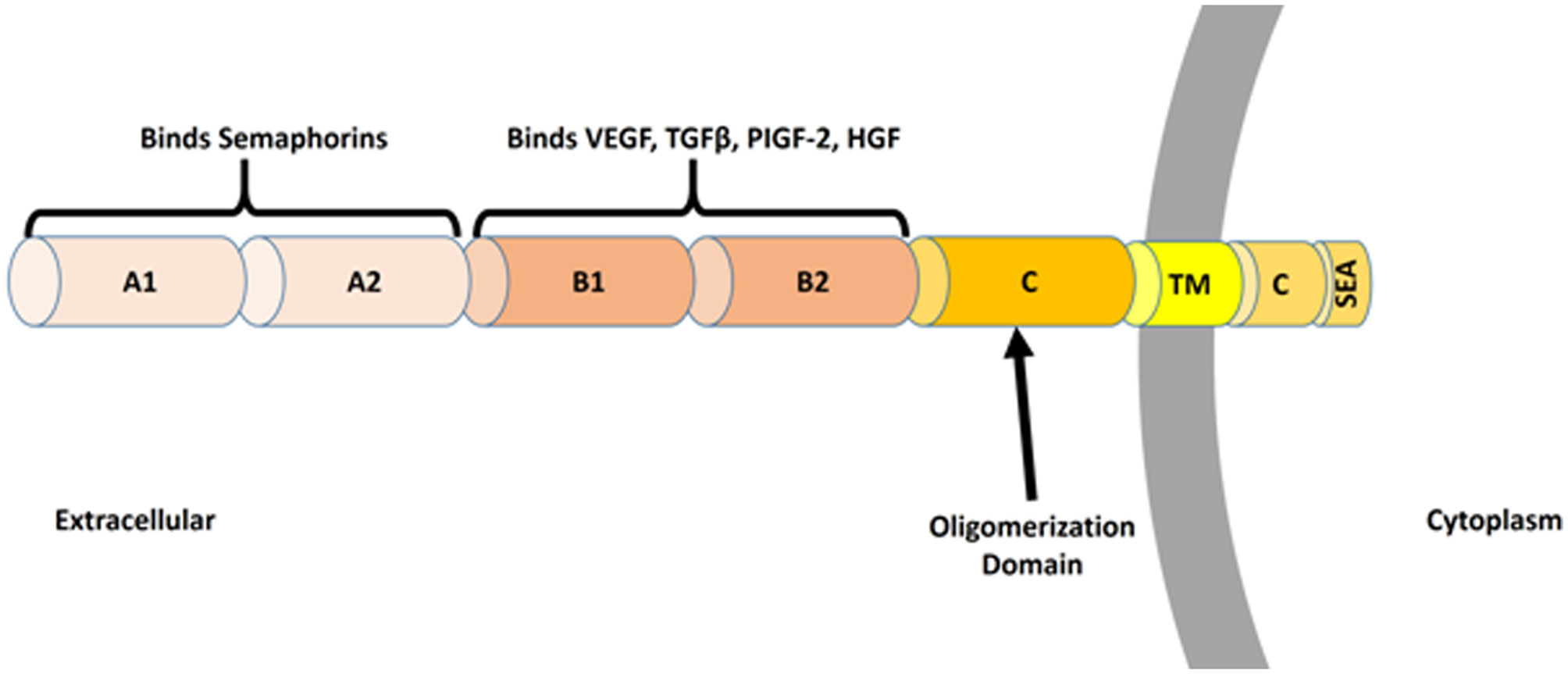
Nakamura F, Goshima Y (2002) Structural and functional relation of neuropilins. Adv Exp Med Biol 515: 55–69. doi: 10.1007/978-1-4615-0119-0_5
    [74] Chaudhary B, Khaled YS, Ammori BJ, et al. (2014) Neuropilin 1: function and therapeutic potential in cancer. Cancer Immunol Immun 63: 81–99. doi: 10.1007/s00262-013-1500-0
    [75] Raimondi C, Fantin A, Lampropoulou A, et al. (2014) Imatinib inhibits VEGF-independent angiogenesis by targeting neuropilin 1-dependent ABL1 activation in endothelial cells. J Exp Med 211: 1167–1183. doi: 10.1084/jem.20132330
    [76] Campos-Mora M, Morales RA, Gajardo T, et al. (2013) Neuropilin-1 in transplantation tolerance. Front Immunol 4: 405.
    [77] Klagsbrun M, Takashima S, Mamluk R (2002) The role of neuropilin in vascular and tumor biology. Adv Exp Med Biol 515: 33–48. doi: 10.1007/978-1-4615-0119-0_3
    [78] Zachary I, Fantin A, Herzog B, et al. (2014) Neuropilin 1 (NRP1) hypomorphism combined with defective VEGF-A binding reveals novel roles for NRP1 in developmental and pathological angiogenesis. Development 141: 556–562. doi: 10.1242/dev.103028
    [79] Campos-Mora M, Morales RA, Perez F, et al. (2015) Neuropilin-1(+) regulatory T cells promote skin allograft survival and modulate effector CD4(+) T cells phenotypic signature. Immunol Cell Biol 93: 113–119. doi: 10.1038/icb.2014.77
    [80] Solomon BD, Mueller C, Chae WJ, et al. (2011) Neuropilin-1 attenuates autoreactivity in experimental autoimmune encephalomyelitis. Proc Natl Acad Sci USA 108: 2040–2045. doi: 10.1073/pnas.1008721108
    [81] Delgoffe GM, Woo SR, Turnis ME, et al. (2013) Stability and function of regulatory T cells is maintained by a neuropilin-1-semaphorin-4a axis. Nature 501: 252–256. doi: 10.1038/nature12428
    [82] Hansen W, Hutzler M, Abel S, et al. (2012) Neuropilin 1 deficiency on CD4+Foxp3+ regulatory T cells impairs mouse melanoma growth. J Exp Med 209: 2001–2016. doi: 10.1084/jem.20111497
    [83] Milpied P, Massot B, Renand A, et al. (2011) IL-17-producing invariant NKT cells in lymphoid organs are recent thymic emigrants identified by neuropilin-1 expression. Blood 118: 2993–3002. doi: 10.1182/blood-2011-01-329268
    [84] Sarris M, Andersen KG, Randow F, et al. (2008) Neuropilin-1 expression on regulatory T cells enhances their interactions with dendritic cells during antigen recognition. Immunity 28: 402–413. doi: 10.1016/j.immuni.2008.01.012
    [85] Bourbie-Vaudaine S, Blanchard N, Hivroz C, et al. (2006) Dendritic cells can turn CD4+ T lymphocytes into vascular endothelial growth factor-carrying cells by intercellular neuropilin-1 transfer. J Immunol 177: 1460–1469. doi: 10.4049/jimmunol.177.3.1460
    [86] Casazza A, Laoui D, Wenes M, et al. (2013) Impeding macrophage entry into hypoxic tumor areas by Sema3A/Nrp1 signaling blockade inhibits angiogenesis and restores antitumor immunity. Cancer Cell 24: 695–709. doi: 10.1016/j.ccr.2013.11.007
    [87] Dejda A, Mawambo G, Daudelin JF, et al. (2016) Neuropilin-1-expressing microglia are associated with nascent retinal vasculature yet dispensable for developmental angiogenesis. Invest Ophth Vis Sci 57: 1530–1536. doi: 10.1167/iovs.15-18598
    [88] Zhang W, Lv Y, Xue Y, et al. (2016b) Co-expression modules of NF1, PTEN and sprouty enable distinction of adult diffuse gliomas according to pathway activities of receptor tyrosine kinases. Oncotarget 7: 59098–59114.
    [89] Glinka Y, Stoilova S, Mohammed N, et al. (2011) Neuropilin-1 exerts co-receptor function for TGF-beta-1 on the membrane of cancer cells and enhances responses to both latent and active TGF-beta. Carcinogenesis 32: 613–621. doi: 10.1093/carcin/bgq281
    [90] Miyauchi JT, Caponegro MD, Chen D, et al. (2017) Deletion of neuropilin 1 from microglia or bone marrow-derived macrophages slows glioma progression. Cancer Res 78: 685–694.
    [91] Osada H, Tokunaga T, Nishi M, et al. (2004) Overexpression of the neuropilin 1 (NRP1) gene correlated with poor prognosis in human glioma. Anticancer Res 24: 547–552.
    [92] Chen L, Miao W, Tang X, et al. (2013) Inhibitory effect of neuropilin-1 monoclonal antibody (NRP-1 MAb) on glioma tumor in mice. J Biomed Nanotechnol 9: 551–558. doi: 10.1166/jbn.2013.1623
    [93] Formolo CA, Williams R, Gordish-Dressman H, et al. (2011) Secretome signature of invasive glioblastoma multiforme. J Proteome Res 10: 3149–3159. doi: 10.1021/pr200210w
    [94] Li X, Tang T, Lu X, et al. (2011) RNA interference targeting NRP-1 inhibits human glioma cell proliferation and enhances cell apoptosis. Mol Med Rep 4: 1261–1266.
    [95] Nasarre C, Roth M, Jacob L, et al. (2010) Peptide-based interference of the transmembrane domain of neuropilin-1 inhibits glioma growth in vivo. Oncogene 29: 2381–2392. doi: 10.1038/onc.2010.9
    [96] Bagci T, Wu JK, Pfannl R, et al. (2009) Autocrine semaphorin 3A signaling promotes glioblastoma dispersal. Oncogene 28: 3537–3550. doi: 10.1038/onc.2009.204
    [97] Treps L, Edmond S, Harford-Wright E, et al. (2016) Extracellular vesicle-transported Semaphorin3A promotes vascular permeability in glioblastoma. Oncogene 35: 2615–2623. doi: 10.1038/onc.2015.317
    [98] Jacob L, Sawma P, Garnier N, et al. (2016) Inhibition of PlexA1-mediated brain tumor growth and tumor-associated angiogenesis using a transmembrane domain targeting peptide. Oncotarget 7: 57851–57865.
    [99] Sulpice E, Plouet J, Berge M, et al. (2008) Neuropilin-1 and neuropilin-2 act as coreceptors, potentiating proangiogenic activity. Blood 111: 2036–2045. doi: 10.1182/blood-2007-04-084269
    [100] Hamerlik P, Lathia JD, Rasmussen R, et al. (2012) Autocrine VEGF-VEGFR2-Neuropilin-1 signaling promotes glioma stem-like cell viability and tumor growth. J Exp Med 209: 507–520. doi: 10.1084/jem.20111424
    [101] Gilbert MR, Dignam JJ, Armstrong TS, et al. (2014) A randomized trial of bevacizumab for newly diagnosed glioblastoma. New Engl J Med 370: 699–708. doi: 10.1056/NEJMoa1308573
    [102] Frei K, Gramatzki D, Tritschler I, et al. (2015) Transforming growth factor-beta pathway activity in glioblastoma. Oncotarget 6: 5963–5977.
    [103] Maxwell M, Galanopoulos T, Neville-Golden J, et al. (1992) Effect of the expression of transforming growth factor-beta 2 in primary human glioblastomas on immunosuppression and loss of immune surveillance. J Neurosurg 76: 799–804. doi: 10.3171/jns.1992.76.5.0799
    [104] Platten M, Wick W, Weller M (2001) Malignant glioma biology: role for TGF-beta in growth, motility, angiogenesis, and immune escape. Microsc Res Tech 52: 401–410. doi: 10.1002/1097-0029(20010215)52:4<401::AID-JEMT1025>3.0.CO;2-C
    [105] Chen ML, Pittet MJ, Gorelik L, et al. (2005) Regulatory T cells suppress tumor-specific CD8 T cell cytotoxicity through TGF-beta signals in vivo. Proc Natl Acad Sci USA 102: 419–424. doi: 10.1073/pnas.0408197102
    [106] Thomas DA, Massague J (2005) TGF-beta directly targets cytotoxic T cell functions during tumor evasion of immune surveillance. Cancer Cell 8: 369–380. doi: 10.1016/j.ccr.2005.10.012
    [107] Wesolowska A, Kwiatkowska A, Slomnicki L, et al. (2008) Microglia-derived TGF-beta as an important regulator of glioblastoma invasion--an inhibition of TGF-beta-dependent effects by shRNA against human TGF-beta type II receptor. Oncogene 27: 918–930. doi: 10.1038/sj.onc.1210683
    [108] Uhl M, Aulwurm S, Wischhusen J, et al. (2004) SD-208, a novel transforming growth factor beta receptor I kinase inhibitor, inhibits growth and invasiveness and enhances immunogenicity of murine and human glioma cells in vitro and in vivo. Cancer Res 64: 7954–7961. doi: 10.1158/0008-5472.CAN-04-1013
    [109] Ueda R, Fujita M, Zhu X, et al. (2009) Systemic inhibition of transforming growth factor-beta in glioma-bearing mice improves the therapeutic efficacy of glioma-associated antigen peptide vaccines. Clin Cancer Res 15: 6551–6559. doi: 10.1158/1078-0432.CCR-09-1067
    [110] Rodon J, Carducci MA, Sepulveda-Sanchez JM, et al. (2015) First-in-human dose study of the novel transforming growth factor-beta receptor I kinase inhibitor LY2157299 monohydrate in patients with advanced cancer and glioma. Clin Cancer Res 21: 553–560. doi: 10.1158/1078-0432.CCR-14-1380
    [111] Falco SD (2012) The discovery of placenta growth factor and its biological activity. Exp Mol Med 44: 1–9. doi: 10.3858/emm.2012.44.1.025
    [112] Dewerchin M, Carmeliet P (2012) PlGF: a multitasking cytokine with disease-restricted activity. Csh Perspect Med 2: 143–152.
    [113] Lassen U, Chinot OL, McBain C, et al. (2015) Phase 1 dose-escalation study of the antiplacental growth factor monoclonal antibody RO5323441 combined with bevacizumab in patients with recurrent glioblastoma. Neuro Oncol 17: 1007–1015. doi: 10.1093/neuonc/nov019
    [114] Snuderl M, Batista A, Kirkpatrick ND, et al. (2013) Targeting placental growth factor/neuropilin 1 pathway inhibits growth and spread of medulloblastoma. Cell 152: 1065–1076. doi: 10.1016/j.cell.2013.01.036
    [115] Guo Y, Wang X, Tian X, et al. (2012) Tumor-derived hepatocyte growth factor is associated with poor prognosis of patients with glioma and influences the chemosensitivity of glioma cell line to cisplatin in vitro. World J Surg Oncol 10: 1–11. doi: 10.1186/1477-7819-10-1
    [116] Wen PY, Schiff D, Cloughesy TF, et al. (2011) A phase II study evaluating the efficacy and safety of AMG 102 (rilotumumab) in patients with recurrent glioblastoma. Neuro Oncol 13: 437–446. doi: 10.1093/neuonc/noq198
    [117] De Groot JF, Prados M, Urquhart T, et al. (2009) A phase II study of XL184 in patients (pts) with progressive glioblastoma multiforme (GBM) in first or second relapse. J Clin Oncol 27: 2047.
    [118] Schiff D, Desjardins A, Cloughesy T, et al. (2016) Phase 1 dose escalation trial of the safety and pharmacokinetics of cabozantinib concurrent with temozolomide and radiotherapy or temozolomide after radiotherapy in newly diagnosed patients with high-grade gliomas. Cancer 122: 582–587. doi: 10.1002/cncr.29798
    [119] Wu HB, Wang Z, Wang QS, et al. (2015) Use of labelled tLyP-1 as a novel ligand targeting the NRP receptor to image glioma. PLoS One 10: e0137676. doi: 10.1371/journal.pone.0137676
    [120] Ying M, Shen Q, Zhan C, et al. (2016) A stabilized peptide ligand for multifunctional glioma targeted drug delivery. J Control Release 243: 86–98. doi: 10.1016/j.jconrel.2016.09.035
    [121] Ying M, Zhan C, Wang S, et al. (2016) Liposome-based systemic glioma-targeted drug delivery enabled by all-d peptides. ACS Appl Mater Inter 8: 29977–29985. doi: 10.1021/acsami.6b10146
    [122] Liu C, Yao S, Li X, et al. (2017) iRGD-mediated core-shell nanoparticles loading carmustine and O6-benzylguanine for glioma therapy. J Drug Target 25: 235–246. doi: 10.1080/1061186X.2016.1238091
    [123] Liu Y, Mei L, Xu C, et al. (2016) Dual receptor recognizing cell penetrating peptide for selective targeting, efficient intratumoral diffusion and synthesized anti-glioma therapy. Theranostics 6: 177–191. doi: 10.7150/thno.13532
    [124] Bechet D, Auger F, Couleaud P, et al. (2015) Multifunctional ultrasmall nanoplatforms for vascular-targeted interstitial photodynamic therapy of brain tumors guided by real-time MRI. Nanomed-Nanotechnol 11: 657–670. doi: 10.1016/j.nano.2014.12.007
    [125] Patnaik A, Lorusso PM, Messersmith WA, et al. (2014) A Phase Ib study evaluating MNRP1685A, a fully human anti-NRP1 monoclonal antibody, in combination with bevacizumab and paclitaxel in patients with advanced solid tumors. Cancer Chemoth Pharm 73: 951–960. doi: 10.1007/s00280-014-2426-8
  • This article has been cited by:

    1. Dan Dubina, Viorel Ungureanu, Local/distortional and overall interactive buckling of thin-walled cold-formed steel columns with open cross-section, 2023, 182, 02638231, 110172, 10.1016/j.tws.2022.110172
    2. Xingyou Yao, EWM-based design method for distortional buckling of cold-formed thin-walled lipped channel sections with holes, 2021, 19, 1551-0018, 972, 10.3934/mbe.2022045
    3. Peng Zhang, M. Shahria Alam, Compression tests of thin-walled cold-formed steel columns with Σ-shaped sections and patterned perforations distributed along the length, 2022, 174, 02638231, 109082, 10.1016/j.tws.2022.109082
    4. Xingyou Yao, Tomasz Trzepieciński, Experimental Study and Proposal to Improve the EWM Design of Cold-Formed Steel Lipped Channel Columns with Circular Holes under Axial Compression, 2021, 2021, 1687-8442, 1, 10.1155/2021/9389121
    5. Junfeng Zhang, Shuran Gao, Bo Li, Liusheng Chu, Huan Wang, The Width-Thickness Ratio Limits of Thin-Walled Steel Elements with Complex Edge Stiffeners, 2023, 13, 2075-5309, 947, 10.3390/buildings13040947
    6. Pradeep Thangavel, Manikandan Palanisamy, Warit Wipulanusat, Krishanu Roy, Investigation of a cold-formed steel inward lipped angle section with triangular brackets under compression: Numerical and theoretical investigations, 2025, 79, 23520124, 109404, 10.1016/j.istruc.2025.109404
  • Reader Comments
  • © 2018 the Author(s), licensee AIMS Press. This is an open access article distributed under the terms of the Creative Commons Attribution License (http://creativecommons.org/licenses/by/4.0)
通讯作者: 陈斌, bchen63@163.com
  • 1. 

    沈阳化工大学材料科学与工程学院 沈阳 110142

  1. 本站搜索
  2. 百度学术搜索
  3. 万方数据库搜索
  4. CNKI搜索

Metrics

Article views(6613) PDF downloads(979) Cited by(2)

Figures and Tables

Figures(3)

/

DownLoad:  Full-Size Img  PowerPoint
Return
Return

Catalog