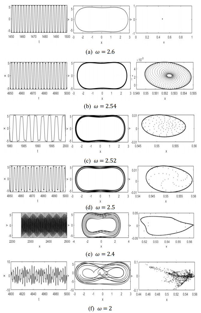
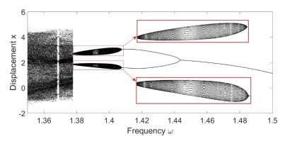
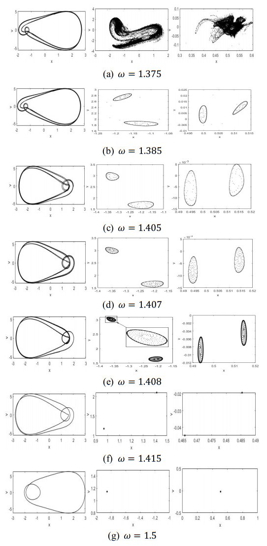
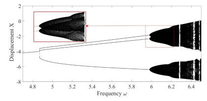
Loading [MathJax]/jax/output/SVG/jax.js
Research article

Research on Hopf bifurcation of vehicle air compressor system with single-pendulum TMD

  • Received: 21 February 2025 Revised: 05 April 2025 Accepted: 22 April 2025 Published: 26 May 2025
  • A two-degree-of-freedom vehicle wheel-rail impact vibration system model was developed, and the equivalent impact stiffness and damping of the rail were fitted by applying ABAQUS, taking into account the high and low irregularity generated by the welded joints of the rail. A wheel-rail periodic interface with fixed impact was selected as the Poincaré map, and the fourth-order Runge–Kutta numerical method with variable step size was used to solve the system response. The dynamic characteristics of the system were investigated using a combination of the bifurcation diagram, phase plane diagram, Poincaré map, time-domain diagram, and frequency-domain diagram. It was verified that the vehicle wheel-rail impact vibration system has Hopf bifurcation, Neimark–Sacker bifurcation, period-doubling bifurcation, and boundary crisis, and rich and complex nonlinear dynamic behavior changes exist. Research on the bifurcation and chaos characteristics of vehicle wheel-rail impact vibration systems can provide a reference for improving the stability of vehicle operation in engineering practice, as well as the prediction and control of chaos in vehicle vibration reduction design.

    Citation: Danyang Wang, Ning Chen. Research on Hopf bifurcation of vehicle air compressor system with single-pendulum TMD[J]. Electronic Research Archive, 2025, 33(5): 3285-3304. doi: 10.3934/era.2025145

    Related Papers:

    [1] Yanlong Zhang, Rui Zhang, Li Wang . Oblique impact dynamic analysis of wedge friction damper with Dankowicz dynamic friction. Electronic Research Archive, 2024, 32(2): 962-978. doi: 10.3934/era.2024047
    [2] Yang Jin, Wanxiang Li, Hongbing Zhang . Transition characteristics of the dynamic behavior of a vehicle wheel-rail vibro-impact system. Electronic Research Archive, 2023, 31(11): 7040-7060. doi: 10.3934/era.2023357
    [3] Junhai Ma, Hui Jiang . Dynamics of a nonlinear differential advertising model with single parameter sales promotion strategy. Electronic Research Archive, 2022, 30(4): 1142-1157. doi: 10.3934/era.2022061
    [4] Wenxin Zhang, Lijun Pei . Bifurcation and chaos in N-type and S-type muscular blood vessel models. Electronic Research Archive, 2025, 33(3): 1285-1305. doi: 10.3934/era.2025057
    [5] Qixiang Wen, Shenquan Liu, Bo Lu . Firing patterns and bifurcation analysis of neurons under electromagnetic induction. Electronic Research Archive, 2021, 29(5): 3205-3226. doi: 10.3934/era.2021034
    [6] Mengting Sui, Yanfei Du . Bifurcations, stability switches and chaos in a diffusive predator-prey model with fear response delay. Electronic Research Archive, 2023, 31(9): 5124-5150. doi: 10.3934/era.2023262
    [7] Leiting Wang, Yang Jin, Wangxiang Li, Chenyang Tang . Analysis of the nonlinear dynamic behavior of longitudinal systems in heavy-haul trains. Electronic Research Archive, 2025, 33(2): 582-599. doi: 10.3934/era.2025027
    [8] Weiyu Li, Hongyan Wang . Dynamics of a three-molecule autocatalytic Schnakenberg model with cross-diffusion: Turing patterns of spatially homogeneous Hopf bifurcating periodic solutions. Electronic Research Archive, 2023, 31(7): 4139-4154. doi: 10.3934/era.2023211
    [9] Zhili Zhang, Aying Wan, Hongyan Lin . Spatiotemporal patterns and multiple bifurcations of a reaction- diffusion model for hair follicle spacing. Electronic Research Archive, 2023, 31(4): 1922-1947. doi: 10.3934/era.2023099
    [10] Fengrong Zhang, Ruining Chen . Spatiotemporal patterns of a delayed diffusive prey-predator model with prey-taxis. Electronic Research Archive, 2024, 32(7): 4723-4740. doi: 10.3934/era.2024215
  • A two-degree-of-freedom vehicle wheel-rail impact vibration system model was developed, and the equivalent impact stiffness and damping of the rail were fitted by applying ABAQUS, taking into account the high and low irregularity generated by the welded joints of the rail. A wheel-rail periodic interface with fixed impact was selected as the Poincaré map, and the fourth-order Runge–Kutta numerical method with variable step size was used to solve the system response. The dynamic characteristics of the system were investigated using a combination of the bifurcation diagram, phase plane diagram, Poincaré map, time-domain diagram, and frequency-domain diagram. It was verified that the vehicle wheel-rail impact vibration system has Hopf bifurcation, Neimark–Sacker bifurcation, period-doubling bifurcation, and boundary crisis, and rich and complex nonlinear dynamic behavior changes exist. Research on the bifurcation and chaos characteristics of vehicle wheel-rail impact vibration systems can provide a reference for improving the stability of vehicle operation in engineering practice, as well as the prediction and control of chaos in vehicle vibration reduction design.


    High-speed rail is a crucial element of modern transportation systems [1,2], with air compressors playing a key role. These compressors supply power to critical subsystems, including braking, suspension, and pneumatic mechanisms, ensuring operational safety and passenger comfort. The reliability of air compressor systems is essential for the efficient functioning of high-speed trains.

    An air compressor serves as a pivotal device for delivering the initial power required to activate equipment, demonstrating extensive utilization across diverse industries, including manufacturing, healthcare, construction, and energy [3,4]. However, the dynamic operational environment of air compressors in high-speed railway vehicles is significantly more complex. The air compressor is usually placed in the train's undercarriage equipment compartment, as shown in Figure 1. Not only do external excitations affecting the train transmit to the air compressor system, but the vibrations generated by the air compressor itself can also propagate to other equipment [5]. Improving its working conditions and minimizing impact on other equipment make vibration isolation and damping of the system an important area for study [6].

    Figure 1.  Air compressor under a train.

    Conventional vibration control methodologies exhibit inherent limitations in addressing nonlinear dynamic characteristics prevalent in modern mechanical systems. Passive damping techniques, constrained by fixed frequency-response characteristics and inadequate load adaptability [7,8], demonstrate diminished efficacy in suppressing bifurcation-induced instabilities under time-varying load-induced parameter drift scenarios. Particularly when systems operate near Hopf bifurcation thresholds, the failure probability of traditional linear control strategies increases significantly [9]. Vibration reduction and isolation are fundamental and enduring challenges in the field of dynamics. The tuned mass damper (TMD), as one of the simplest and most reliable damping devices, is widely used to reduce the resonant vibration of structures [10]. A classical TMD consists of an auxiliary mass attached to the primary structure, stiffness element, and damping element [11]. Specifically, when the host structure undergoes excitation-induced vibration, the TMD captures vibrational energy through phase-differential resonance mechanisms and achieves targeted energy dissipation via viscous damping [12,13]. This passive energy transfer strategy ensures reliability while circumventing the high energy consumption and algorithmic complexity inherent in active control systems [14,15]. It has been widely applied in the vibration control of various engineering structures, such as civil (e.g., buildings, bridges) [16,17,18,19,20,21], mechanical [22,23,24,25,26,27,28,29], and aerospace engineering [30,31].

    Nonlinear vibration absorbers are also diverse in structure and form. For example, the bi-directional rail variable friction pendulum-tuned mass damper (BRVFP-TMD) proposed by Xiang et al. regulates energy dissipation characteristics through the dynamic adjustment of the friction interface [32]. The nonlinear single-mass two-frequency pendulum tuned mass damper developed by Viet and Nghi suppresses horizontal vibration by utilizing the nonlinear frequency characteristics [33]. The superelastic SMA helical spring damper designed by the Lv team realizes adaptive stiffness adjustment through the phase transformation of shape memory alloys [34]. In addition, scholars such as Liu et al. analyzed the influence of geometric nonlinear effects on the performance of tuned mass dampers on top of flexible structures [35]. The suspended multiple mass pendulum damper developed by Sun et al. improves the vibration reduction efficiency through collaborative vibration [36]. Shaw and Bahadori studied the centrifugal pendulum vibration absorber operating in a fluid, which optimizes the tuning parameters by combining fluid dynamics [27]. These studies expand the design boundaries of nonlinear vibration absorbers from the dimensions of friction control, material properties, geometric nonlinearity, and multi-physics field coupling.

    This study proposes a pendulum-type TMD as a vibration reduction device for train air compressors. The pendulum absorber inherently exhibits nonlinear characteristics, where nonlinear factors simultaneously present significant challenges and unique opportunities for innovation [37]. On the one hand, nonlinear systems inherently pose analytical and computational difficulties [38]. On the other hand, the complexity is amplified by typical nonlinear phenomena, including bifurcation behaviors, multi-solution coexistence, and chaos. Nonlinear dynamics research in pendulum systems exhibits multidimensional exploration. Kim et al. developed centrifugal pendulum absorbers optimizing energy dissipation through geometric nonlinear damping [39], while Han et al. revealed chaotic transitions in irrational pendulum systems under resonance [40]. Amer et al.'s 3DOF double pendulum model demonstrated complex subharmonic responses near resonance [41]. Notably, Nana et al. validated synchronization control in electromechanical pendulums via phase-space reconstruction [42], and Qin and Zhang's fractal basin quantification method established new chaos evaluation criteria for double pendulums [43]. These studies advance the understanding of nonlinear phenomena in pendulum systems through damping optimization, chaos characterization, and complex system modeling.

    Analyzing bifurcation mechanisms is essential for predicting and mitigating instability in nonlinear suspension systems. Bifurcation means the instability of the original solution of the system, and the main basic bifurcation forms include doubling bifurcation, Hopf bifurcation, and transcritical bifurcation. The Hopf bifurcation of the periodic solution of the nonlinear system will cause the original periodic solution to gradually evolve into a quasi-periodic solution, and its harmonic components will become more complex. Hopf bifurcation marks the onset of self-excited vibrations, a critical instability threshold in high-speed compressors. Avoiding this threshold is essential for safe operation. While existing bifurcation control frameworks demonstrate effectiveness in general rotating machinery, their direct applicability to compressor systems lacks empirical validation. Furthermore, despite the proven efficacy of pendulum-TMD configurations in suppressing linear resonances within conventional structures, the nonlinear interaction mechanisms between such dampers and Hopf bifurcation dynamics under train-mounted compressors' operational constraints demand systematic investigation. This critical gap between established theoretical frameworks and domain-specific operational complexities underscores the necessity for focused investigation into bifurcation control mechanisms within pendulum-type compressor-TMD vibration suppression systems.

    To address these unresolved issues, this paper establishes a nonlinear coupled model integrating train air compressor vibrations with single-pendulum TMD dynamics. Building on nonlinear fundamental theory [44,45,46], bifurcation research frameworks [47,48], and Li et al.'s foundational analysis of compressor nonlinearity [49], we systematically characterize bifurcation thresholds governed by key parameters. Sections 2 and 3 establish the system's mechanical model and governing equations and validate its dynamics via numerical simulations, while Section 4 analyzes bifurcation pathways and chaos mechanisms under parameter variations. Theoretical analysis and numerical simulations reveal three chaos transition mechanisms. Through theoretical analysis and numerical simulations, we explore the bifurcation behavior of the system and the different paths into chaos. This innovative research not only fills a gap in the study of nonlinear dynamics of train air compressors but also contributes to the development of reliable vibration-damping solutions for high-speed trains. Furthermore, it provides a generalized framework applicable to a broader range of mechanical applications.

    In this paper, a suspension vibration reduction system model for a vehicle air compressor with a single-pendulum vibration absorber is established, as illustrated in Figure 2. The air compressor, with a mass of M​, is connected to the frame through a transverse rigid spring with stiffness Kx, a vertical spring with stiffness Ky​, a transverse damper with damping coefficient Cx, and a vertical damper with damping coefficient Cy. The connection points are separated by a distance y0. x is the horizontal displacement of the air compressor, y is the vertical displacement of the air compressor, and θ is the pendulum angle of the pendulum absorber. Suspended from the lower end of the compressor is a pendulum with a mass m​ and a swing length l​, where the mass of the rod is neglected. The upper end of the air compressor is mounted on the vehicle body. Assuming the vehicle body undergoes a vertical displacement Y cos ωt, the system represents a forced vibration system under displacement excitation.

    Figure 2.  Dynamic model under displacement excitation.

    According to the second type of Lagrange's equations, in the differential equations of motion of the system, the horizontal displacement of the suspension block M during vibration is denoted as x. and the vertical displacement is y. Then, in the vibration process, the displacement of the pendulum is

    xm=x+l sin θym=yl cos θ. (1)

    The kinetic energy T of the system is

    T=TM+Tm=12M(˙x2+˙y2)+12m[(˙x+l cos θ˙θ)2+(y+l sin θ˙θ)2]. (2)

    TM=12M(˙x2+˙y2)is the total kinetic energy of the compressor, and Tm=12m[(˙x+l cos θ˙θ)2+(y+l sin θ˙θ)2] is the kinetic energy of the pendulum.

    The potential energy U of the system is

    U=12kxx2+12kyy02+Mg[yy(0)]+mg[ymym(0)]. (3)

    Substituting y0=Y cos ωty, y(0)=0, ym(0)=y(0)l into Eq (3) yields

    U=12kxx2+12ky(Y cos ωty)2+Mgy+mg[ym+l]=12kxx2+12ky(Y cos ωty)2+Mgy+mg[yl cos θ+l]. (4)

    The system dissipates energy and introduces a dissipation function, whose expression is defined by

    R=12(kxv2ix+kyv2iy+kzv2iz), (5)

    in this system

    Rx=12cx˙x2,
    Ry=12cy(˙yωYsinωτ)2˙y2,
    Rθ=12cθ[(˙x+l cos θ˙θ)2+(˙y+l sin θ˙θ)2],
    R=Rx+Ry+Rθ=12cx˙x2+12cy(˙yωYsinωτ)2˙y2+12cθ[(˙x+l cos θ˙θ)2+(˙y+l sin θ˙θ)2]. (6)

    According to the second-kind Lagrange equation

    ddt(L˙qi)Lqi+R˙qi=Qi, (7)

    thereinto

    L=TU=12M(˙x2+˙y2)+12m[(˙x+l cos θ˙θ)2+(˙y+l sin θ˙θ)2]12kxx212ky(Y cos ωty)2Mgymg(yl cos θ+l)#. (8)

    Deriving and substituting Eqs (6) and (8) into Eq (7) and simplifying, we get

    (M+m)¨x+ml¨θ cos θml sin θ˙θ2+kxx+cx˙x+cθ˙x+cθl cos θ˙θ=0(M+m)¨y+ml¨θ sin θ+ml cos θ˙θ2+(M+m)g+ky(Y cos ωty)+cy(2˙yωY sin ωt)+cθ˙y+cθlsinθ˙θ=0ml2¨θ+ml¨x cos θ+m¨yl sin θ+mgl sin θcθ˙xl sin θ˙θ+cθ˙ylcosθ˙θ=0. (9)

    When θ is small,  sin θθ,  cos θ1, Eq (9) reduces to

    (M+m)¨x+ml¨θmlθ˙θ2+kxx+cx˙x+cθ˙x+cθl˙θ=0(M+m)¨y+ml¨θθ+ml˙θ2+(M+m)g+ky(Y cos ωty)+cy(2˙yωY sin ωτ)+cθ˙y+cθlθ˙θ=0ml2¨θ+ml¨x+m¨ylθ+mglθcθ˙xlθ˙θ+cθ˙yl˙θ=0. (10)

    When exploring the dynamic properties of the system in depth, the dimensionless treatment significantly reduces the parameter dimensions, provides a powerful tool for analyzing their specific effects on the dynamic behavior of the system, and facilitates the focusing and deepening of the research problem. Therefore, the equation is dimensionless, and the order is

    mM+m=n,kxM+m=k1,kyM+m=k2,cxM+m=c1,cyM+m=c2,cθM+m=a1,cθm=a2,F0=FM+m. (11)

    After substituting Eq (11) into Eq (10), the differential equation of motion of the system after non-dimensionalization is obtained as

    ¨x+nl¨θnlθ˙θ2+k1x+c1˙x+a1˙x+a1l˙θ=0¨y+nl¨θθ+nl˙θ2+g+k2(Y cos ωty)+c2(2˙yωY sin ωτ)+a1˙y+a1lθ˙θ=0l2¨θ+l¨x+¨ylθ+glθa2˙xlθ˙θ+a2˙yl˙θ=0. (12)

    When the vertical displacement excitation Y cos ωt is equated to a vertical external excitation F cos ωt, as shown in Figure 3, the differential equations of motion for a single pendulum vibration-absorbing vehicle compressor suspension damping system are obtained as follows:

    ¨x+nl¨θnlθ˙θ2+k1x+c1˙x+a1˙x+a1l˙θ=0¨y+nl¨θθ+nl˙θ2+gk2y+2c2˙y+a1˙y+a1lθ˙θ=F0(ω) sin (ωt+φ)l2¨θ+l¨x+¨ylθ+glθa2˙xlθ˙θ+a2˙yl˙θ=0, (13)

    which F0(ω) sin (ωt+φ)=k2(Y cos ωt)+c2(ωY sin ωt).

    Figure 3.  Schematic of the three-degree-of-freedom oscillator.

    In the simulation setup, an initial deflection angle θ0 is introduced to the single-pendulum TMD. This angle is set to account for the minor angular displacements caused by track irregularities and longitudinal unevenness of the train. The presence of this initial angle ensures that the pendulum can effectively function as a tuned mass damper, providing both mass and tuning effects. The initial deflection angle θ0 depends on the specific conditions of the track and train dynamics.

    When the vertical displacement excitation lny is equated to a vertical external excitation yn, the differential equations of motion for a single pendulum vibration-absorbing vehicle compressor suspension damping system are obtained as follows:

    yn+1=yn+K.

    yn+1 is determined by yn and slope K, and slope K can be obtained by weighting the average of the following four slopes K1, K2, K3 and K4.

    {K1=Hf(xn,yn)K2=Hf(xn+H2,yn+K12)K3=Hf(xn+H2,yn+K22)K4=Hf(xn+H,yn+K3), (14)

    wherein H is the step size, and K1 is the slope at the beginning of the step length segment; K2 and K3 are the slopes of the midpoint of the step segment, and the slopes K1 and K2 are used by the Euler method to determine the value of y at xn+h/2. K4 is the slope at the end of the step segment, and the slope of K3 determines the value of y at xn+H. Then the slope of K is

    K=K1+2K2+2K3+K46. (15)

    The command invoked in this article is

    [x,y]=ode45(m,tspan,y0), (16)

    where m is the file used to store the nonlinear differential equations to be solved by the system; tspan is the vector specifying the range of the independent variables, [x0,x1]; y0 is the boundary condition of the function, i.e., y0=y(x0).

    In the process of analyzing the dynamics of the system, experts and scholars have established the Poincaré map to make the motion form of the collision vibration system clearer and more definite. In the process of analysis, the continuous system is discretized, the phase trajectory of its motion is studied by changing into a discrete system, and the dimensionality of the system is reduced and changed from n to n1 dimension. If a cross-section (Poincaré cross-section) cross-sections the track, the image formed when it crosses the track is a Poincaré image, and the point xn+1 that passes through the cross-section the next time is called the mapping of the point xn that last crossed the cross-section.

    xn+1=f(xn)(n=0,1,2,3) (17)

    This is the Poincaré mapping, which reduces a continuous motion to a discrete mapping while keeping all the properties of the system unchanged, by which a dimensionality reduction is achieved, so that the stability of the nonlinear dynamics is equivalent to the stability of the immobile point for the study of the system. Its numerical realization is generally referred to as the Poincaré cross-section method, and the key lies in the selection of the Poincaré cross-section. Since this paper is a smooth dynamical system, the time-periodic condition can be used for the Poincaré cross-section:

    Σ:mod(t,2π/ω)=0. (18)

    Select a set of dimensionless system parameters M=1, m=0.1, kx=1, ky=1, and Y=10 (displacement excitation amplitude), l=0.2 (length of intervals of pendulum), and h=0.00001. In the simulation setup, an initial deflection angle θ0 is introduced to the single-pendulum TMD. This angle is set to account for the minor angular displacements caused by track irregularities and longitudinal unevenness of the train, θ0=0.2 rad. The frequency parameter ω is the bifurcation parameter, and the four-stage four-order Runge–Kutta algorithm is used to numerically simulate the system. The control variable method is used to study it. The above parameters are used as the benchmark to draw the frequency parameters of the air compressor suspension damping model system ω and phase shifts X, with a bifurcation interval of ω[2,2.7], as shown in Figure 4.

    Figure 4.  Bifurcation chart of X.

    It can be observed in Figure 5(a) that when the system parameter ω incrementally traverses ω=2.6, the Poincaré section is a stable point, which increases with ω. The stability point begins to spread outward and gradually expands until ω=2.54, and a stable Hopf circle appears in the system, as shown in Figure 5(b). Hopf bifurcation acts as an instability precursor: the system's transition from equilibrium to limit cycle oscillations fundamentally alters its phase-space geometry. This creates the necessary conditions for subsequent period-doubling events by destabilizing the original attractor basin. The ω continues to decrease, the circle begins to gradually oscillate and rupture, and the points in the circle gradually sparse; when ω=2.4, the torus begins to twist and deform and gradually begins to rupture; the discrete points are attracted to the trajectory of the chaotic attractor, as shown in Figure 5(e). When ω=2, the rudiments of the chaotic attractor are formed, and when ω>2, the system is ready to enter the chaotic motion.

    Figure 5.  Transverse time history diagram, displacement velocity phase diagram, and Poincaré cross-section.

    Select a set of dimensionless system parameters M=1, m=0.1, kx=1, ky=1, and Y=10 (displacement excitation amplitude), l=0.2 (length of intervals of pendulum), h=0.00001, and θ0=0.2 rad. The frequency parameter ω is the bifurcation parameter, and the four-stage four-order Runge–Kutta algorithm is used to numerically simulate the system. The control variable method is used to study it. The above parameters are used as the benchmark to draw the frequency parameters of the air compressor suspension damping model system ω and phase shifts X, with a bifurcation interval of ω[1.35,1.5], as shown in Figure 6.

    Figure 6.  Bifurcation chart of X.

    The change of this motion behavior is more complex, and the specific way of entering chaos can be studied with the help of the Poincaré mapping method. The periodic cross-section on three degrees of freedom is selected as the Poincaré cross-section of the system, and the lower phase diagram and Poincaré cross-section diagram of the fixed frequency parameters ω are obtained by computer simulation, as shown below.

    When the bifurcation parameter is ω=1.5, the projection of the system on the Poincaré section is shown in Figure 7(g), and there is only one equilibrium point, indicating that the system is in single-periodic motion. With the decrease of ω, the equilibrium point first occurs at ω=1.415, the bifurcation changes from 1 stable point to 2 stable points, and the system is in period-two motion. The two limit rings expand and deform, as shown in Figure 7(f)(b); the process is the continuous expansion and enlargement of the two limit rings and finally enters chaos, as shown in Figure 7(a). The Hopf-induced limit cycle exhibits parametric sensitivity in its amplitude-frequency relationship, which triggers symmetry-breaking effects. This drives the system into the period-doubling regime through gradual torsional deformation of the attractor.

    Figure 7.  Transverse time history diagram, vertical Poincaré cross-section, and transverse Poincaré cross-section.

    Select a set of dimensionless system parameters M=1, m=0.1, kx=1, ky=1, cx=0.2, cy=0.5, cθ=0.1, and Y=20 (displacement excitation amplitude), l=0.2 (length of intervals of pendulum), h=0.00001, and θ0=0.2 rad. The frequency parameter ω is the bifurcation parameter, the four-stage four-order Runge–Kutta algorithm is used to numerically simulate the system, and we use the control variable method to study it. The above parameters are used as the benchmark. The bifurcation diagram of the frequency parameters ω and phase displacement X of the air compressor suspension damping model system is plotted as shown in Figure 8.

    Figure 8.  Bifurcation chart of X.

    The periodic cross-section with three degrees of freedom is still selected as the Poincaré cross-section of the system, and the phase diagram and Poincaré cross-section diagram in the three directions of sag direction, transverse direction, and rotation of the fixed frequency parameter ω are obtained by computer simulation.

    The Poincaré map of the system is selected in three directions: vertical, horizontal, and rotational. The cross-sectional diagram is used to reveal how the system migrates from periodic motion to chaotic motion. With the Poincaré map, it is clear how the system transitions from a single-periodic motion via a Hopf bifurcation to a chaotic motion. When the bifurcation parameter is ω=5.97, the projection of the system on the Poincaré section is as shown in the figure, where the system is in period-three motion. With the increase of the parameter ω, these three points begin to deform and expand to the periphery, and three limit rings are generated when ω=5.98131, as shown in Figure 9. As ω continues to increase, the three limit rings expand and deform, as shown in Figures 10–13. This corresponds to a continuous expansion of the three limit rings. The system undergoes period-three motions leading to chaos. The torus begins to rupture, and the points are gradually attracted to the chaotic attractor torus; the system begins to enter chaos, resulting in a chaotic attractor as shown in Figure 14.

    Figure 9.  ω=5.97. (a) Vertical displacement-velocity phase diagram; (b) transverse displacement-velocity phase diagram; (c) rotary displacement velocity phase diagram; (d) vertical Poincaré cross-section; (e) transverse Poincaré cross-section; (f) rotary Poincaré cross-section.
    Figure 10.  ω=5.98131. (a) Vertical displacement-velocity phase diagram; (b) transverse displacement-velocity phase diagram; (c) rotary displacement velocity phase diagram; (d) vertical Poincaré cross-section; (e) transverse Poincaré cross-section; (f) rotary Poincaré cross-section.
    Figure 11.  ω=5.995. (a) Vertical displacement-velocity phase diagram; (b) transverse displacement-velocity phase diagram; (c) rotary displacement velocity phase diagram; (d) vertical Poincaré cross-section; (e) transverse Poincaré cross-section; (f) rotary Poincaré cross-section.
    Figure 12.  ω=6.2. (a) Vertical displacement-velocity phase diagram; (b) transverse displacement-velocity phase diagram; (c) rotary displacement velocity phase diagram; (d) vertical Poincaré cross-section; (e) transverse Poincaré cross-section; (f) rotary Poincaré cross-section.
    Figure 13.  ω=6.3. (a) Vertical displacement-velocity phase diagram; (b) transverse displacement-velocity phase diagram; (c) rotary displacement velocity phase diagram; (d) vertical Poincaré cross-section; (e) transverse Poincaré cross-section; (f) rotary Poincaré cross-section.
    Figure 14.  ω=6.5. (a) Vertical displacement-velocity phase diagram; (b) transverse displacement-velocity phase diagram; (c) rotary displacement velocity phase diagram; (d) vertical Poincaré cross-section; (e) transverse Poincaré cross-section; (f) rotary Poincaré cross-section.

    This study advances nonlinear dynamics research in mechanical systems by systematically characterizing previously underexplored chaotic transition mechanisms in train compressor suspension systems with pendulum vibration absorption. Three critical advances emerge from our findings:

    1) We establish a novel classification framework identifying three distinct bifurcation pathways to chaos (single Hopf, period-two, and period-three motion) through systematic parameter-space exploration. This resolves a key knowledge gap in prior studies that predominantly focused on individual bifurcation types without examining their interconnections in practical mechanical configurations. The demonstrated transition sequence—from Hopf bifurcation through period-doubling to chaotic attractor formation—provides a mechanistic blueprint for predicting instability thresholds in rotating machinery.

    2) Our numerical simulations reveal parameter-dependent behavioral polymorphism where similar macroscopic motions conceal fundamentally different transition dynamics. This finding undermines conventional stability assessment methodologies by revealing that superficial kinematic similarities can obscure fundamental disparities in intrinsic failure mechanisms. The observed coexistence of periodic unlocking phases and jumping phenomena offers new diagnostic criteria for early chaos detection in vibration-damping systems.

    3) The identified parameter sensitivity relationships (particularly the nonlinear correlation between damping coefficients and chaos onset thresholds) enable predictive optimization of vibration absorber designs. This directly addresses practical engineering challenges by establishing quantitative guidelines for maintaining compressor stability while avoiding chaotic regimes—a critical advancement beyond traditional trial-and-error damper adjustment methods.

    These theoretical breakthroughs carry immediate practical implications. The derived stability maps allow targeted parameter selection to suppress chaotic transitions, while the characterized attractor evolution patterns provide a novel basis for developing adaptive vibration control algorithms. Future work will validate these predictive models through controlled rotor dynamics experiments, ultimately bridging the gap between nonlinear theory and industrial vibration mitigation practices.

    The authors declare they have not used Artificial Intelligence (AI) tools in the creation of this article.

    This research was funded by 2024 Gansu Provincial University Teachers' Innovation Fund Project, grant number 2024A-239.

    The authors declare there is no conflict of interest.


    [1] J. Zhang, Z. Xiang, Q. Zhang, S. Feng, Z. Yu, X. Wang, et al., A method to improve the tribological performance of Cu-based powder metallurgy friction materials for the high-speed trains braking system: Enhancement of the performance of the friction block disc spring, Wear, 566–567 (2025), 205751.https://doi.org/10.1016/j.wear.2025.205751
    [2] Y. Lin, Y. Qin, J. Wu, M. Xu, Impact of high-speed rail on road traffic and greenhouse gas emissions, Nat. Clim. Change, 11 (2021), 952–957. https://doi.org/10.1038/s41558-021-01190-8 doi: 10.1038/s41558-021-01190-8
    [3] S. Zhong, K. Ou, Z. Jin, Q. Zhang, X. Zhang, Y. X. Wang, Improved optimal sliding mode control and operating strategy for turbine-based air compressor in automotive fuel cells with driving cycles analysis, Energy, 324 (2025), 135743. https://doi.org/10.1016/j.energy.2025.135743 doi: 10.1016/j.energy.2025.135743
    [4] Y. Wu, H. Bao, J. Fu, X. Wang, J. Liu, Review of recent developments in fuel cell centrifugal air compressor: Comprehensive performance and testing techniques, Int. J. Hydrogen Energy, 48 (2023), 32039–32055. https://doi.org/10.1016/j.ijhydene.2023.04.262 doi: 10.1016/j.ijhydene.2023.04.262
    [5] F. Braghin, S. Bruni, F. Resta, Active yaw damper for the improvement of railway vehicle stability and curving performances: Simulations and experimental results, Veh. Syst. Dyn. , 44 (2006), 857–869. https://doi.org/10.1080/00423110600733972 doi: 10.1080/00423110600733972
    [6] Z. Guo, L. Dai, M. Chi, Y. Li, J. Sun, Numerical and experimental study on adaptive stiffness yaw damper for suppressing abnormal vibration of high-speed trains, Trans. Can. Soc. Mech. Eng. , 49 (2025), 24–34. https://doi.org/10.1139/tcsme-2024-0087 doi: 10.1139/tcsme-2024-0087
    [7] H. Li, K. Bi, Q. Han, R. Ma, A state-of-the-art review on negative stiffness-based structural vibration control, Eng. Struct. , 323 (2025), 119247. https://doi.org/10.1016/j.engstruct.2024.119247 doi: 10.1016/j.engstruct.2024.119247
    [8] S. J. Patil, G. R. Reddy, State of art review-base isolation systems for structures, Int. J. Emerging Technol. Adv. Eng. , 2 (2012), 438–453.
    [9] D. D. Tandel, P. Wahi, A. Chatterjee, Ensuring supercritical Hopf bifurcation in tool chatter using a nonresonant limit cycle absorber, J. Sound Vib. , 604 (2025), 118958. https://doi.org/10.1016/j.jsv.2025.118958 doi: 10.1016/j.jsv.2025.118958
    [10] J. Dai, Z. D. Xu, P. P. Gai, H. W. Li, Effect of frequency dependence of large mass ratio viscoelastic tuned mass damper on seismic performance of structures, Soil Dyn. Earthquake Eng. , 130 (2020), 105998. https://doi.org/10.1016/j.soildyn.2019.105998 doi: 10.1016/j.soildyn.2019.105998
    [11] S. Jiang, K. Bi, R. Ma, K. Xu, H closed-form solution of tuned mass damper enhanced with negative stiffness element (TMD-NS) for structural vibration control, J. Sound Vib. , 586 (2024), 118510. https://doi.org/10.1016/j.jsv.2024.118510 doi: 10.1016/j.jsv.2024.118510
    [12] J. Song, K. Bi, R. Ma, K. Xu, Q. Han, Optimum design and performance evaluation of inerter‐based dampers for seismic protection of adjacent bridges, Structures, 55 (2023), 1277–1291. https://doi.org/10.1016/j.istruc.2023.06.093 doi: 10.1016/j.istruc.2023.06.093
    [13] K. Xu, Q. Dai, K. Bi, G. Fang, Y. Ge, Closed‐form design formulas of TMDI for suppressing vortex‐induced vibration of bridge structures, Struct. Control Health Monit. , 29 (2022), e3016. https://doi.org/10.1002/stc.3016 doi: 10.1002/stc.3016
    [14] H. Yu, O. Øiseth, M. Zhang, F. Xu, G. Hu, Tuned mass damper design for vortex-induced vibration control of a bridge: influence of vortex-induced force model, J. Bridge Eng. , 28 (2023), 04023021. https://doi.org/10.1061/JBENF2.BEENG-5958 doi: 10.1061/JBENF2.BEENG-5958
    [15] M. Zhang, F. Xu, Tuned mass damper for self-excited vibration control: Optimization involving nonlinear aeroelastic effect, J. Wind Eng. Ind. Aerodyn. , 220 (2022), 104836. https://doi.org/10.1016/j.jweia.2021.104836 doi: 10.1016/j.jweia.2021.104836
    [16] X. Fang, H. Hao, K. Bi, H. Ding, X. Yang, J. Song, et al., Seismic response control of shear frame structure using a novel tuned-mass type composite column, Eng. Struct. , 322 (2025), 119160. https://doi.org/10.1016/j.engstruct.2024.119160 doi: 10.1016/j.engstruct.2024.119160
    [17] S. Jiang, R. Ma, K. Bi, H. Li, X. Du, Negative stiffness enhanced TMD for seismic response mitigation of bridges isolated with friction pendulum system (FPS), Eng. Struct. , 331 (2025), 119978. https://doi.org/10.1016/j.engstruct.2025.119978 doi: 10.1016/j.engstruct.2025.119978
    [18] T. Zhang, W. Wang, X. Li, W. Shi, Vibration mitigation of an integrated structure consisting of a monopile offshore wind turbine and aquaculture cage under earthquake, wind, and wave loads, Mech. Adv. Mater. Struct. , 30 (2023), 627–646. https://doi.org/10.1080/15376494.2021.2020941 doi: 10.1080/15376494.2021.2020941
    [19] S. Jiang, R. Ma, K. Bi, X. Du, J. Song, Negative stiffness enhanced tuned mass damper (NS-TMD) for seismic induced response mitigation of isolated bridges, Eng. Struct. , 325 (2025), 119416. https://doi.org/10.1016/j.engstruct.2024.119416 doi: 10.1016/j.engstruct.2024.119416
    [20] F. Nikravesh, H. Toopchi-Nezhad, Application of viscoelastic tuned mass dampers in vibration mitigation of steel joist jack arch floor structures, Shock Vib. , 2022 (2022), 5196600. https://doi.org/10.1155/2022/5196600 doi: 10.1155/2022/5196600
    [21] L. Wang, S. Nagarajaiah, Y. Zhou, W. Shi, Experimental study on adaptive-passive tuned mass damper with variable stiffness for vertical human-induced vibration control, Eng. Struct. , 280 (2023), 115714. https://doi.org/10.1016/j.engstruct.2023.115714 doi: 10.1016/j.engstruct.2023.115714
    [22] J. Jiang, X. Dong, J. Lian, Y. Jia, Research on semi-active vibration reduction of offshore wind turbine structure combined eddy current theory with tuned mass dampers, Renewable Energy, 234 (2024), 121185. https://doi.org/10.1016/j.renene.2024.121185 doi: 10.1016/j.renene.2024.121185
    [23] Y. Gao, E. Zhai, S. Li, Z. Zhang, Z. Xu, G. Zhang, et al., Integrated design and real-world application of a tuned mass damper (TMD) with displacement constraints for large offshore monopile wind turbines, Ocean Eng. , 292 (2024), 116568. https://doi.org/10.1016/j.oceaneng.2023.116568 doi: 10.1016/j.oceaneng.2023.116568
    [24] Z. Luan, P. Dou, Y. Chen, H. Zhang, Y. Ku, Optimization study of a tuned mass damper for a large monopile wind turbine, Energies, 17 (2024), 4460. https://doi.org/10.3390/en17174460 doi: 10.3390/en17174460
    [25] B. Zhu, Y. Wu, C. Sun, D. Sun, An improved inerter-pendulum tuned mass damper and its application in monopile offshore wind turbines, Ocean Eng. , 298 (2024), 117172. https://doi.org/10.1016/j.oceaneng.2024.117172 doi: 10.1016/j.oceaneng.2024.117172
    [26] W. Jing, J. Feng, S. Song, X. Cheng, Seismic performance improvement of liquid storage tank based on base-isolation and pendulum tuned mass damper, Nucl. Eng. Des. , 417 (2024), 112867. https://doi.org/10.1016/j.nucengdes.2023.112867 doi: 10.1016/j.nucengdes.2023.112867
    [27] S. W. Shaw, R. Bahadori, Tuning of centrifugal pendulum vibration absorbers operating in a fluid, Nonlinear Dyn. , 112 (2024), 741–755. https://doi.org/10.1007/s11071-023-09087-1 doi: 10.1007/s11071-023-09087-1
    [28] Y. Yue, C. Li, K. Jia, Y. Zhang, J. Tian, Optimization of the seismic performance of a steel-concrete wind turbine tower with the tuned mass damper, Buildings, 12 (2022), 1474. https://doi.org/10.3390/buildings12091474 doi: 10.3390/buildings12091474
    [29] N. Sarkar, A. D. Ghosh, Application of conical spring to maintain tuning of mass damper for wave-induced vibration control of offshore jacket platform subjected to changes in natural frequency, Ocean Eng. , 312 (2024), 119352. https://doi.org/10.1016/j.oceaneng.2024.119352 doi: 10.1016/j.oceaneng.2024.119352
    [30] Z. Q. Hu, L. Yang, Y. S. Wang, L. Wei, Y. Chen, Tuned mass damper on spacecraft reaction wheel assembly, Appl. Acoust. , 210 (2023), 109456. https://doi.org/10.1016/j.apacoust.2023.109456 doi: 10.1016/j.apacoust.2023.109456
    [31] W. A. Shen, S. Zhu, Y. L. Xu, An experimental study on self-powered vibration control and monitoring system using electromagnetic TMD and wireless sensors, Sensors Actuat. A - Phys. , 180 (2012), 166–176. https://doi.org/10.1016/j.sna.2012.04.011 doi: 10.1016/j.sna.2012.04.011
    [32] Y. Xiang, P. Tan, H. He, H. Yao, X. Zheng, K. Yang, A novel bi-directional rail variable friction pendulum-tuned mass damper (BRVFP-TMD), Mech. Syst. Signal Process. , 197 (2023), 110396. https://doi.org/10.1016/j.ymssp.2023.110396 doi: 10.1016/j.ymssp.2023.110396
    [33] L. D. Viet, N. B. Nghi, On a nonlinear single-mass two-frequency pendulum tuned mass damper to reduce horizontal vibration, Eng. Struct. , 81 (2014), 175–180. https://doi.org/10.1016/j.engstruct.2014.09.038 doi: 10.1016/j.engstruct.2014.09.038
    [34] H. Lv, B. Huang, Vibration reduction performance of a new tuned mass damper with pre-strained superelastic SMA helical springs, Int. J. Struct. Stab. Dyn. , 24 (2024), 2450047. https://doi.org/10.1142/S0219455424500470 doi: 10.1142/S0219455424500470
    [35] X. Liu, Z. Qu, Y. Huang, A. Wada, Effects of geometric nonlinearities on the vibration reduction performance of tuned mass dampers on top of flexible structures, Adv. Struct. Eng. , 26 (2023), 2565–2571. https://doi.org/10.1177/13694332221149500 doi: 10.1177/13694332221149500
    [36] H. Sun, H. He, Y. Cheng, S. Cheng, Theoretical and experimental research on damping performance of suspended multiple mass pendulums damper, Structures, 55 (2023), 169–184. https://doi.org/10.1016/j.istruc.2023.06.048 doi: 10.1016/j.istruc.2023.06.048
    [37] N. Chen, S. Cao, Y. Hou, An indirect harmonic balance method based on frequency response functions simplification for periodical response analysis of local nonlinearity systems, Comput. Struct. , 310 (2025), 107663. https://doi.org/10.1016/j.compstruc.2025.107663 doi: 10.1016/j.compstruc.2025.107663
    [38] Y. Chen, L. Hou, R. Lin, J. Song, T. Y. Ng, Y. Chen, A harmonic balance method combined with dimension reduction and FFT for nonlinear dynamic simulation, Mech. Syst. Signal Process. , 221 (2024), 111758. https://doi.org/10.1016/j.ymssp.2024.111758 doi: 10.1016/j.ymssp.2024.111758
    [39] J. H. Kim, J. H. Ri, H. Jang, C. U. Choe, Centrifugal pendulum vibration absorber with geometric nonlinear damping, J. Sound Vib. , 571 (2024), 118031. https://doi.org/10.1016/j.jsv.2023.118031 doi: 10.1016/j.jsv.2023.118031
    [40] N. Han, H. Zhang, P. Lu, Z. Liu, Resonance response and chaotic analysis for an irrational pendulum system, Chaos, Solitons Fractals, 182 (2024), 114812. https://doi.org/10.1016/j.chaos.2024.114812 doi: 10.1016/j.chaos.2024.114812
    [41] A. Amer, W. Zhang, T. S. Amer, H. Li, Nonlinear vibration analysis of a 3DOF double pendulum system near resonance, Alexandria Eng. J. , 113 (2025), 262–286. https://doi.org/10.1016/j.aej.2024.11.018 doi: 10.1016/j.aej.2024.11.018
    [42] B. Nana, S. B. Yamgoué, P. Woafo, Dynamics of an autonomous electromechanical pendulum-like system with experimentation, Chaos, Solitons Fractals, 152 (2021), 111475. https://doi.org/10.1016/j.chaos.2021.111475 doi: 10.1016/j.chaos.2021.111475
    [43] B. Qin, Y. Zhang, A novel global perspective: Characterizing the fractal basins of attraction and the level of chaos in a double pendulum, Chaos, Solitons Fractals, 189 (2024), 115694. https://doi.org/10.1016/j.chaos.2024.115694 doi: 10.1016/j.chaos.2024.115694
    [44] X. H. Huang, J. Yang, L. Bai, X. E. Wang, X. Ren, Theoretical solutions for auxetic laminated beam subjected to a sudden load, Structures, 28 (2020), 57–68. https://doi.org/10.1016/j.istruc.2020.08.030 doi: 10.1016/j.istruc.2020.08.030
    [45] M. J. Wu, X. H. Huang, I. Azim, J. Zhu, H. Chen, Nonlinear dynamic and vibration characteristics of metamaterial shallow arches, Eur. J. Mech. A. Solids, 102 (2023), 105084. https://doi.org/10.1016/j.euromechsol.2023.105084 doi: 10.1016/j.euromechsol.2023.105084
    [46] M. J. Wu, I. Azim, X. H. Huang, A novel technique for low-velocity impact of shallow arches, Comput. Struct. , 298 (2024), 107386. https://doi.org/10.1016/j.compstruc.2024.107386 doi: 10.1016/j.compstruc.2024.107386
    [47] Q. Wu, N. Chen, M. Yao, Y. Niu, C. Wang, Nonlinear dynamic analysis of FG fluid conveying micropipes with initial imperfections, Int. J. Struct. Stab. Dyn. , 25 (2025), 2550017. https://doi.org/10.1142/S0219455425500178 doi: 10.1142/S0219455425500178
    [48] Q. Wu, N. Zhao, M. Yao, Y. Niu, C. Wang, Free vibrations and frequency sensitivity of bionic microcantilevers with stress concentration effect, Int. J. Struct. Stab. Dyn., (2025), 2650222.https://doi.org/10.1142/S0219455426502226
    [49] Y. Li, X. Wang, S. Chen, H. Lu, Nonlinear dynamic response and global stability of an air compressor vibration system, J. Low Freq. Noise Vibr. Act. Control, 38 (2019), 1081–1095. https://doi.org/10.1177/1461348418817695 doi: 10.1177/1461348418817695
  • Reader Comments
  • © 2025 the Author(s), licensee AIMS Press. This is an open access article distributed under the terms of the Creative Commons Attribution License (http://creativecommons.org/licenses/by/4.0)
通讯作者: 陈斌, bchen63@163.com
  • 1. 

    沈阳化工大学材料科学与工程学院 沈阳 110142

  1. 本站搜索
  2. 百度学术搜索
  3. 万方数据库搜索
  4. CNKI搜索

Metrics

Article views(220) PDF downloads(23) Cited by(0)

Other Articles By Authors

/

DownLoad:  Full-Size Img  PowerPoint
Return
Return

Catalog