Citation: Alexander V. Perig, Nikolai N. Golodenko. 2D CFD description of the kinematic effects of movable inlet and outlet die wall transport motion and punch shape geometry on the dynamics of viscous flow during ECAE through Segal 2θ-dies for a range of channel angles[J]. AIMS Materials Science, 2017, 4(6): 1240-1275. doi: 10.3934/matersci.2017.6.1240
| [1] | Masami Kojima, Pusit Mitsomwang, Shigeru Nagasawa . Effect of cutter tip angle on cutting characteristics of acrylic worksheet subjected to punch/die shearing. AIMS Materials Science, 2016, 3(4): 1728-1747. doi: 10.3934/matersci.2016.4.1728 |
| [2] | Omar Ouabouch, Imad Ait Laasri, Mounir Kriraa, Mohamed Lamsaadi . Investigation of novel turbulator with and without twisted configuration under turbulent forced convection of a CuO/water nanofluid flow inside a parabolic trough solar collector. AIMS Materials Science, 2023, 10(1): 112-138. doi: 10.3934/matersci.2023007 |
| [3] | Michael Z. Hu, Peng Lai . Substrate effect on nanoporous structure of silica wires by channel-confined self-assembly of block-copolymer and sol-gel precursors. AIMS Materials Science, 2015, 2(4): 346-355. doi: 10.3934/matersci.2015.4.346 |
| [4] | Bhavik Ardeshana, Umang Jani, Ajay Patel, Anand Joshi . An approach to modelling and simulation of single-walled carbon nanocones for sensing applications. AIMS Materials Science, 2017, 4(4): 1010-1028. doi: 10.3934/matersci.2017.4.1010 |
| [5] | Habibur Rahman, Altab Hossain, Mohammad Ali . Experimental investigation on cooling tower performance with Al2O3, ZnO and Ti2O3 based nanofluids. AIMS Materials Science, 2024, 11(5): 935-949. doi: 10.3934/matersci.2024045 |
| [6] | Guadalupe Sanchez-Olivares, Fausto Calderas, Antonio Sanchez-Solis, Luis Medina-Torres, Leonardo R. Moreno, Octavio Manero . Assessment of extrusion-sonication process on flame retardant polypropylene by rheological characterization. AIMS Materials Science, 2016, 3(2): 620-633. doi: 10.3934/matersci.2016.2.620 |
| [7] | Igor A Chaves, Robert E Melchers, Barbara Jardim do Nascimento, Jordan Philips, Mark Masia . Effects of inter-cavity corrosion on metallic wall ties in masonry structures. AIMS Materials Science, 2022, 9(2): 311-324. doi: 10.3934/matersci.2022019 |
| [8] | Utpal K. Dhar, Md. Farabi Rahman, Mustafa Oguzhan Ayanoglu, Ahammad Abdullah . Welding on C67 steel grade sheet: Influence of the parameters and post welding heat treatment. AIMS Materials Science, 2023, 10(3): 453-464. doi: 10.3934/matersci.2023025 |
| [9] | Sumesh Narayan, Ananthanarayanan Rajeshkannan . Densification behaviour of sintered aluminum composites during hot deformation. AIMS Materials Science, 2018, 5(5): 902-915. doi: 10.3934/matersci.2018.5.902 |
| [10] | Christos Stavrogiannis, Filippos Sofos, Theodoros. E. Karakasidis, Denis Vavougios . Investigation of water desalination/purification with molecular dynamics and machine learning techniques. AIMS Materials Science, 2022, 9(6): 919-938. doi: 10.3934/matersci.2022054 |
SPD is Severe Plastic Deformation;
ECAP is Equal Channel Angular Pressing;
ECAE is Equal Channel Angular Extrusion;
CFD is Computational Fluid Dynamics;
BCs are boundary conditions;
a; a is the channel width of the ECAE die, [m];
2θ is the channel intersection angle of the ECAE die, [deg];
The 2θ-die is the ECAE die ABC–abc with channel intersection angle 0° < 2θ < 180°;
2θ die of Segal geometry is the angular die ABC–abc with channel intersection angle ∠ (ABC) = ∠ (abc) = 2θ without external and internal radii in channel intersection zone;
2θ0 is the punch angle, [deg];
2θ = 2θ0, [deg] is experimentally determined geometric condition for dead zone size reduction and for minimization of dangerous macroscopic rotation in workpiece volume, obtained with physical simulation techniques only for the case of the fixed die walls of Segal ECAE die with Vab = Vbc = 0;
Re is Reynolds number of viscous workpiece model (given more fully below);
U0 is a characteristic punching velocity of ECAE forming, where vector U0 is directed into ECAE punching direction [m/s];
u; u is x-projection of velocity of the point of viscous continuum, [m/s], where u = u/U0;
V; V is y-projection of velocity of the point of viscous continuum, [m/s], where V = V/U0;
Vab is dimensional velocity of inlet die wall ab, [m/s];
Vbc is dimensional velocity of outlet die wall bc, [m/s];
Vab (Vbc)↑↑U0 is called as "Vab (Vbc) & U0 are parallel" and means that velocity vectors Vab (Vbc) and U0 are parallel to each other and directed into one side, along ECAE punching direction U0;
Vab (Vbc)↑↓U0 is called as "Vab (Vbc) & U0 are anti-parallel" and means that velocity vectors Vab (Vbc) and U0 are parallel to each other but directed into opposite sides, i.e., Vab (Vbc) is directed into opposite side to ECAE punching direction U0;
X; Y; X; Y are Cartesian rectangular coordinates of the points of viscous continuum, [m], where x=ˉx/ˉa; y=ˉy/ˉa or x=Re⋅ut; y=Re⋅vt;
ζ; ˉζ is a curl function for viscous continuum, [1/s], where ζ=ˉζˉa/ˉU0;
ˉνvis is dimensional kinematic viscosity of viscous continuum, [m2/s];
ˉηvis=ˉνvis⋅ˉρ is dimensional dynamic viscosity of viscous continuum, [Pa·s];
ˉρ is the dimensional density of viscous physical model of polymer material, [kg/m3];
ψ; ˉψ is a flow function, [m2/s], where ψ=ˉψ/(ˉU0ˉa);
p; p is ECAE punching pressure, [Pa], where p=ˉp/(ˉρˉU20);
t; t is time, [s], where t=ˉtˉηvis/(ˉρˉa2) or t=ˉtˉνvis/(ˉa2);
Re=ˉU0ˉaˉρ/ˉηvis is Reynolds number of viscous continuum;
N is the quantity of ordinate steps along the channel width;
ζ; ˉξ is the horizontal coordinate step along x-axis;
η; ˉη is the vertical coordinate step along y-axis;
tit; ˉtit is time iteration step, [s];
ttr; ˉttr is transition time, [s];
k is iteration number;
n is the number of time step;
i; j are numbers of difference grid cells, where i corresponds x-axis, and j corresponds y.
Severe Plastic Deformation (SPD) techniques [1,2,3,4,5,6,7,8,9,10,11,12,13,14,15,16,17,18,19,20,21,22,23,24,25,26,27,28,29,30] are closely associated with material forming (or material pressure working) methods and their application has increased over the last 40–50 years [1,3,4,5,6,7,8,10,11,12,13,14,15,16,17,18,19,20,21,22,23,24,25,27,28,29,30]. The classical SPD processing methods are Segal's Equal Channel Angular Extrusion (ECAE) and Equal Channel Angular Pressing (ECAP) material forming techniques [1,3,4,5,6,7,8,10,11,12,13,14,15,16,17,18,19,20,21,22,23,25,28,29,30], which appeared in the 70s years in the USSR (Figures 1–20). Classical ECAE or ECAP is based on one or several extrusion passes of a lubricated metal or polymer material through die tooling with two intersecting channels of equal cross-section [1,3,4,5,6,7,8,10,11,12,13,14,15,16,17,18,19,20,21,22,23,25,28,29,30]. Material processing by ECAE results in the accumulation of large shear strains and material structure refinement with physical properties enhancement [1,7,8,29]. The standard ECAE die geometry ABC–abc for SPD processing is the so-called Segal 2θ-die geometry, where the inlet AB–ab and outlet BC–bc die channels have an intersection angle 2θ (Figures 1, 2, 17–20). Moreover Segal ECAE 2θ-dies have neither external nor internal radii at the channel intersection points B; b and usually have fixed motionless die walls ab and bc in the inlet and outlet die channels (Figures 1, 2, 17–20). This apparent simplicity and materials science-related effectiveness of the ECAE technique has attracted tremendous world-wide research attention to this pressure-forming scheme for the last 20–25 years and distinguished this process among other ways of lateral extrusion in material forming. However, the relatively mature ECAE process has not found wide manufacturing applications due to such shortcomings as restricted length of the pressure formed workpiece (intermittence or discontinuity of process), edge effects, and dead zone formation. The restricted length problem is beyond the scope of the present research. Edge effects during ECAE are associated with the problem of high material waste in multi-pass ECAE-induced processing and were partially addressed in previous researches [11,12,17].
Research into the mechanics of ECAE-induced dead zone formation has been regularly reported in numerous publications for the last 20 years. Practical problems of partial or complete dead zone elimination in ECAE pressure forming are usually solved by changing the die tooling geometry [6,11,12,14,15,20,30], by varying the classical punch shape [7,8,17,18], and by kinematic introduction of additional translational motion in the die walls [14,22]. Geometric ideas concerning punch shape variation are very limited and restricted in these schemes due to the geometric simplicity of the classical ECAE die tooling shapes. As a result, the possible modified geometric punch shapes are usually inclined or bevel-shaped forms of the punch surface [7,8,17,18]. Therefore numerous discussions concerning the importance and priority of researches by Nejadseyfi et al. [7,8] or by Perig et al. [17,18] are rather superficial because in 2017 we know that geometric design ideas which are shown in Figures 1(a), 2, 17–20 for the first time were reported 30 years ago in restricted access patents of the USSR in 1987 by other researchers. The geometric ideas of that patent were completely unavailable for the SPD-research community due to the 30 years-long non-disclosure period. As a result, the geometric ideas of an inclined punch shape introduction for more efficient ECAE realization were independently and simultaneously re-invented by Nejadseyfi et al. [7,8] and by Perig et al. [17,18]. These above mentioned facts confirm the actuality and the importance of the present research study, which improves consistency, integrity and sustainability of SPD-related research results between different scientific schools and research communities.
The complex rheological behavior of ECAE worked materials requires the introduction of a wide variety of computational techniques for analytical and numerical ECAE description.
Applications of Upper Bound Method (UBM) with trial continuous and discontinuous velocity fields provide a simple phenomenological estimation of energy-power parameters for metal workpieces in ECAE and is outlined in the works [5,13,16,19,30], and others. Koutcheryaev [3,4] has applied continuum mechanics based plastic flow description of the ECAE process for mathematical simulation of SPD-induced flow lines. T th et al. [29] and Rejaeian et al. [25] have applied flow field based continual description of textures evolution during ECAE of metals through flow function introduction.
Finite Element Method (FEM)-based ECAE simulation is mainly accomplished with an introduction of commercial FEM software and is outlined in the works of Minakowski [6], Nejadseyfi et al. [7,8], Perig et al. [11,12,17], and the others. The article by Perig et al. [17] is FEM-based solution of plastic flow problem for ECAE metal workpiece forming through 2θ-die with an application of inclined punch shape, derived only for ECAE die with 2θ = 75° and only for the case of the fixed die walls with Vab = Vbc = 0.
For three recent years, one could see major research interest in the introduction of fluid mechanics techniques [3,4,6,9,10,14,15,18,20,21,22,23,25,26,28] to the solution of ECAE problems [1,3,4,5,6,7,8,10,11,12,13,14,15,16,17,18,19,20,21,22,23,25,28,29,30] in the works of Koutcheryaev [3,4], Minakowski [6], Perig et al. [10,14,15,18,20,21,22,23], and Rejaeian et al. [25]. The article by Perig et al. [18] is a CFD-based solution of a viscous flow problem for ECAE forming through 2θ-die with an application of inclined punch shape, derived only for an ECAE die with 2θ = 75° and only for the case of the fixed die walls with Vab = Vbc = 0. This interest is assumed by growing applications of ECAP SPD techniques to processing of polymers [1,6,9,10,14,15,18,20,21,22,23] and powder materials where viscosity effects become essential.
At the same time, the phenomenological description of polymer materials flow through Segal 2θ-dies with movable die walls and different punch shapes with introduction of Navier-Stokes equations has not been adequately addressed in previously known publications [1,3,4,5,6,7,8,10,11,12,13,14,15,16,17,18,19,20,21,22,23,25,28,29,30]. This underlines the importance of the present research, dealing with fluid dynamics 2D simulation of material flow through non-rectangular Segal 2θ-dies with channel intersection angles of 2θ > 0° with movable inlet and outlet die walls and different punch shape geometries.
Another flow problem during ECAE material processing through the acute-angled Segal 2θ-dies with 2θ < 90° and 2θ > 90° is connected with the formation of large dead zones (3) in the viscous material flow in Figures 1(b), 19 as well as enormous and dangerous mixing Δα of viscous material (2) in Figures 1(b), 19 during viscous continuum ECAE through the acute-angled dies with channel intersection angles of 2θ < 90° when standard classical rectangular punches (4) are applied (Figures 1(b), 19). So simple physical simulation experiments in Figures 1(b), 19 for viscous continuum ECAE through the die ABC–abc with 2θ = 75° confirm the disadvantages of using a standard punch (4) with rectangular shape AD–ad (2θ0 = 90°) in Figures 1(b), 19. It is very important to note that known approaches in published articles [1,3,4,5,6,7,8,10,11,12,13,14,15,16,17,18,19,20,21,22,23,25,28,29,30] have never addressed the possibility of changing the standard rectangular punch shape AD–ad in Figures 1(b), 19 for material ECAE through the acute-angled and obtuse-angled Segal 2θ-dies with 2θ < 90° and 2θ > 90°, and for Segal 2θ-dies with movable inlet and outlet die walls.
This fact emphasizes the importance and underlines the prime novelty of the present article addressing the fluid dynamics viscous description of the influence of classical (Figures 1(b), 19) and novel modified 2θ-inclined or 2θ-beveled (Figures 1(a), 1(c), 2, 17, 18, 20) punch shape AD–ad and motion of inlet ab and outlet cd external die walls on viscous flow features of processed workpieces during ECAE SPD pressure forming through a Segal 2θ-die with channel intersection angle 2θ > 0° with movable inlet and outlet die walls.
The present article is focused on the experimental and theoretical description of viscous workpiece flow through 2θ angular dies of Segal geometry during ECAE with a classical rectangular punch and a novel modified 2θ0-inclined or 2θ0-beveled punch for Segal 2θ-dies with movable inlet and outlet die walls.
The aim of the present research is the phenomenological continuum mechanics based description of viscous workpiece flow through 2θ angular dies of Segal geometry during ECAE with an application of classical rectangular and novel modified 2θ0-inclined or 2θ0-beveled punch shapes for Segal 2θ-dies with movable inlet and outlet die walls.
The subject of the present research is the process of ECAE working through the 2θ angular dies of Segal geometry with viscous flow of polymeric workpiece models, forced by the external action of classical rectangular and novel modified 2θ0-inclined or 2θ0-beveled punch shapes for Segal 2θ-dies with movable inlet and outlet die walls.
The object of the present research is to establish the characteristics of the viscous flow of workpiece models through the subject dies with respect to workpiece material rheology, geometric parameters of different punch shapes and movable inlet and outlet die walls of the subject dies on technological process of viscous ECAE-assisted working by pressure.
The experimental novelty of the present article is based on the introduction of initial circular gridlines to study the punch shape influence on viscous workpiece ECAE flow through the 2θ angular dies of Segal geometry for the case of the fixed motionless die walls with Vab = Vbc = 0.
The prime novelty statement of the present research is the numerical finite-difference solution of Navier-Stokes equations in the curl transfer form for the viscous workpiece flow through the 2θ angular dies of Segal geometry with movable inlet and outlet die walls during ECAE, taking into account the classical rectangular and novel modified 2θ0-inclined or 2θ0-beveled punch shapes with due account for independent alternating transportation motion of inlet and outlet die walls of Segal 2θ-dies.
Physical simulation techniques using plasticine workpiece models are often used in material forming practice [2,5,10,11,12,13,14,15,16,17,18,19,20,21,22,23,27,29,30].
In order to estimate the character of viscous flow during ECAE through a 2θ angular die of Segal geometry ABC–abc under the action of a classical rectangular punch and novel modified 2θ0-inclined or 2θ0-beveled punch shapes in the case of the fixed die walls with Vab = Vbc = 0 we have utilized physical simulation techniques in Figures 1, 2, 17–20. The plasticine workpiece models in Figures 1, 2, 17–20 have been extruded through an ECAE die ABC–abc with channel intersection angle 2θ = 75° using a standard punch (4) with rectangular shape (2θ0 = 90°) in Figures 1(b), 19 and novel modified 2θ0 = 75°-inclined or 2θ0 = 75°-beveled punch (1) in Figures 1(a), 1(c), 2, 17, 18, 20 as the first experimental approach to polymeric materials flow (Figures 1, 2, 17–20).
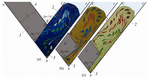 Figure 1. Physical simulation with soft models-based experiments of punch shape (1, 4) influence on ECAE flow of viscous continuum (2) through the acute-angled Segal non-rectangular die ABC–abc with channel intersection angle 2θ = 75° < 90°; (4) is classical punch of rectangular shape AD–da with 2θ0 = 90° in (b); (1) is modified shape of inclined 2θ0-punch AD–da in (a) and (c) with 2θ0 = 2θ
= 75° < 90°; (3) is the experimentally derived shape of the dead zone for viscous material flow during ECAE in the case of the fixed die walls with Vab =
Vbc = 0.
Figure 1. Physical simulation with soft models-based experiments of punch shape (1, 4) influence on ECAE flow of viscous continuum (2) through the acute-angled Segal non-rectangular die ABC–abc with channel intersection angle 2θ = 75° < 90°; (4) is classical punch of rectangular shape AD–da with 2θ0 = 90° in (b); (1) is modified shape of inclined 2θ0-punch AD–da in (a) and (c) with 2θ0 = 2θ
= 75° < 90°; (3) is the experimentally derived shape of the dead zone for viscous material flow during ECAE in the case of the fixed die walls with Vab =
Vbc = 0.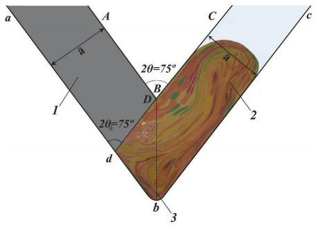 Figure 2. Soft physical model of the workpiece after 3 ECAE passes through acute-angled Segal 2θ-die via route C with modified shape of 2θ0-inclined or 2θ0-beveled punch, where 2θ0 = 2θ
= 75° < 90° and Vab
= Vbc = 0.
Figure 2. Soft physical model of the workpiece after 3 ECAE passes through acute-angled Segal 2θ-die via route C with modified shape of 2θ0-inclined or 2θ0-beveled punch, where 2θ0 = 2θ
= 75° < 90° and Vab
= Vbc = 0.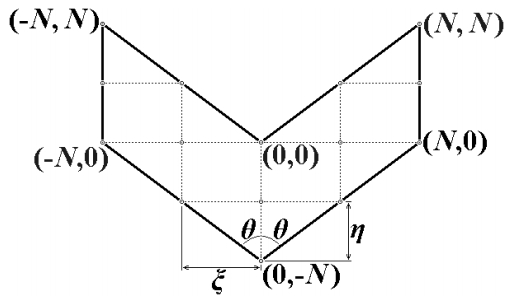 Figure 3. The finite difference mesh for the 2θ equal channel angular die of Segal geometry.
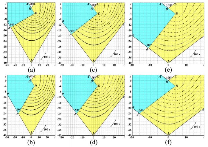 Figure 4. CFD-derived computational flow lines for the Segal dies with 2θ = 60° (a, b), 2θ = 75° (c, d), and 2θ = 105° (e, f), derived for the rectangular punch AD–da (2θ0 = 90°) (a, c, e) and for the beveled inclined punch AD–da (2θ0 = 2θ) (b, d, f) for Vab
= Vbc = 0.
Figure 4. CFD-derived computational flow lines for the Segal dies with 2θ = 60° (a, b), 2θ = 75° (c, d), and 2θ = 105° (e, f), derived for the rectangular punch AD–da (2θ0 = 90°) (a, c, e) and for the beveled inclined punch AD–da (2θ0 = 2θ) (b, d, f) for Vab
= Vbc = 0.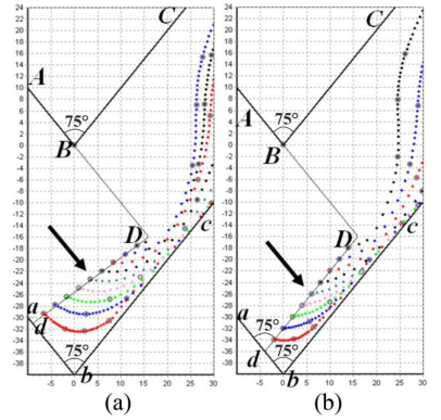 Figure 5. CFD-derived computational flow lines for the Segal dies with 2θ = 75° (a, b), derived for the rectangular punch AD–da (2θ0 = 90°) (a) and for the beveled inclined punch AD–da (2θ0 = 2θ) (b) at the final stage of ECAE-assisted deformation for Vab = Vbc = 0.
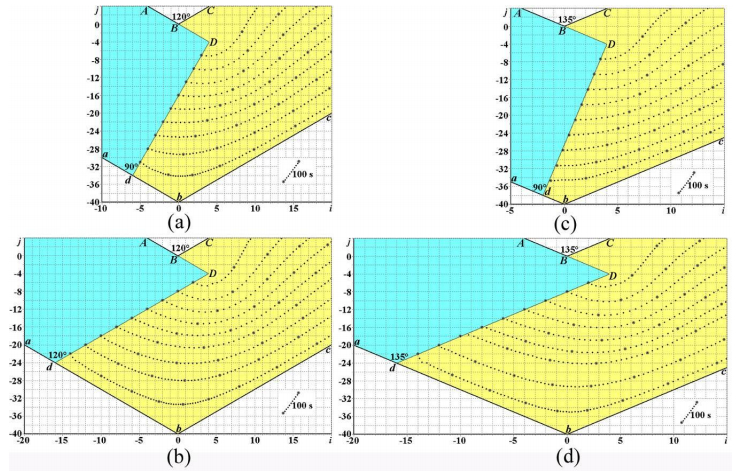 Figure 6. CFD-derived computational flow lines for the Segal dies with 2θ = 120° (a, b), and 2θ = 135° (c, d), derived for the rectangular punch AD–da (2θ0 = 90°) (a, c) and for the beveled inclined punch AD–da (2θ0 = 2θ) (b, d) for Vab = Vbc
= 0.
Figure 6. CFD-derived computational flow lines for the Segal dies with 2θ = 120° (a, b), and 2θ = 135° (c, d), derived for the rectangular punch AD–da (2θ0 = 90°) (a, c) and for the beveled inclined punch AD–da (2θ0 = 2θ) (b, d) for Vab = Vbc
= 0.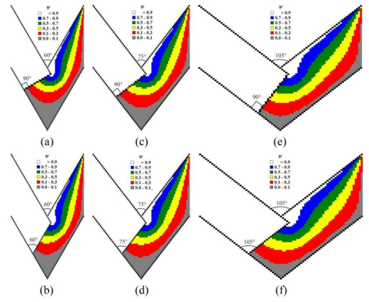 Figure 7. CFD-derived computational isolines of flow function ψ for the Segal dies with 2θ = 60° (a, b), 2θ = 75° (c, d), and 2θ = 105° (e, f), derived for the rectangular punch AD–da (2θ0 = 90°) (a, c, e) and for the beveled inclined punch AD–da (2θ0 = 2θ) (b, d, f) for Vab
= Vbc = 0.
Figure 7. CFD-derived computational isolines of flow function ψ for the Segal dies with 2θ = 60° (a, b), 2θ = 75° (c, d), and 2θ = 105° (e, f), derived for the rectangular punch AD–da (2θ0 = 90°) (a, c, e) and for the beveled inclined punch AD–da (2θ0 = 2θ) (b, d, f) for Vab
= Vbc = 0.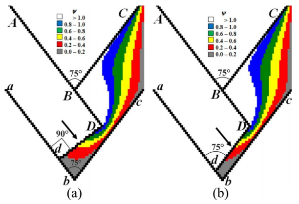 Figure 8. CFD-derived computational isolines of flow function ψ for the Segal dies with 2θ = 75° (a, b), derived for the rectangular punch AD–da (2θ0 = 90°) (a) and for the beveled inclined punch AD–da (2θ0 = 2θ) (b) at the final stage of ECAE-assisted deformation for Vab = Vbc = 0.
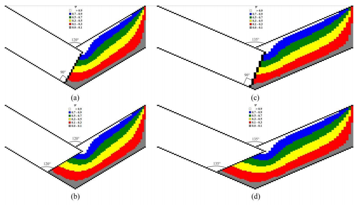 Figure 9. CFD-derived computational isolines of flow function ψ for the Segal dies with 2θ = 120° (a, b), and 2θ = 135° (c, d), derived for the rectangular punch AD–da (2θ0 = 90°) (a, c) and for the beveled inclined punch AD–da (2θ0 = 2θ) (b, d) for Vab = Vbc
= 0.
Figure 9. CFD-derived computational isolines of flow function ψ for the Segal dies with 2θ = 120° (a, b), and 2θ = 135° (c, d), derived for the rectangular punch AD–da (2θ0 = 90°) (a, c) and for the beveled inclined punch AD–da (2θ0 = 2θ) (b, d) for Vab = Vbc
= 0.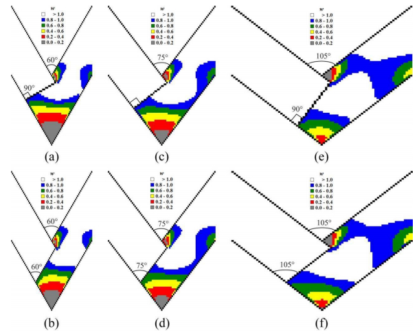 Figure 10. CFD-derived computational isolines of full flow velocity w for the Segal dies with 2θ = 60° (a, b), 2θ = 75° (c, d), and 2θ = 105° (e, f), derived for the rectangular punch AD–da (2θ0 = 90°) (a, c, e) and for the beveled inclined punch AD–da (2θ0 = 2θ) (b, d, f) for Vab
= Vbc = 0.
Figure 10. CFD-derived computational isolines of full flow velocity w for the Segal dies with 2θ = 60° (a, b), 2θ = 75° (c, d), and 2θ = 105° (e, f), derived for the rectangular punch AD–da (2θ0 = 90°) (a, c, e) and for the beveled inclined punch AD–da (2θ0 = 2θ) (b, d, f) for Vab
= Vbc = 0.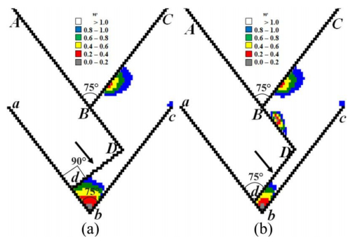 Figure 11. CFD-derived computational isolines of full flow velocity w for the Segal dies with 2θ = 75° (a, b), derived for the rectangular punch AD–da (2θ0 = 90°) (a) and for the beveled inclined punch AD–da (2θ0 = 2θ) (b) at the final stage of ECAE-assisted deformation for Vab = Vbc = 0.
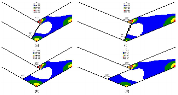 Figure 12. CFD-derived computational isolines of flow velocity w for the Segal dies with 2θ = 120° (a, b), and 2θ = 135° (c, d), derived for the rectangular punch AD–da (2θ0 = 90°) (a, c) and for the beveled inclined punch AD–da (2θ0 = 2θ) (b, d) for Vab = Vbc
= 0.
Figure 12. CFD-derived computational isolines of flow velocity w for the Segal dies with 2θ = 120° (a, b), and 2θ = 135° (c, d), derived for the rectangular punch AD–da (2θ0 = 90°) (a, c) and for the beveled inclined punch AD–da (2θ0 = 2θ) (b, d) for Vab = Vbc
= 0.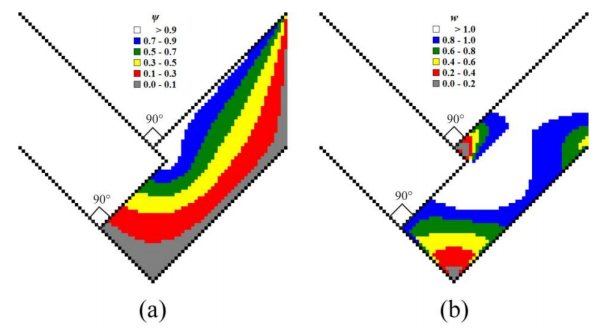 Figure 13. CFD-derived computational isolines of flow function ψ (a) and full flow velocity w (b) for the Segal dies with 2θ = 90°, derived for the standard rectangular punch AD–da (2θ0 = 90°) (a, b) for Vab = Vbc = 0.
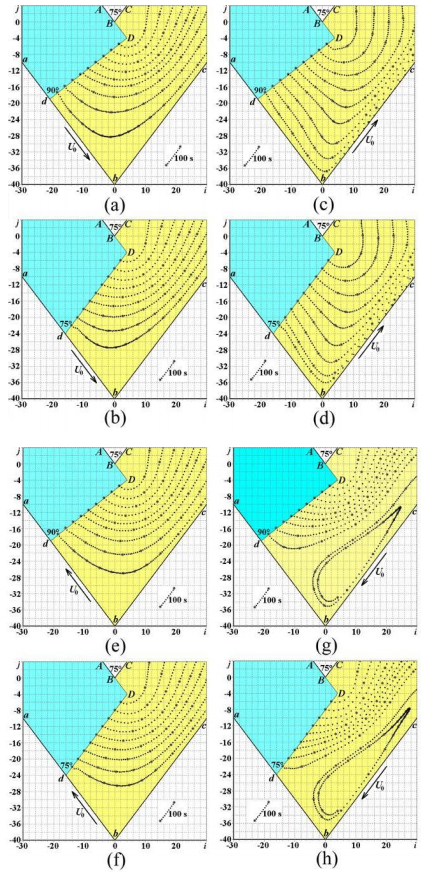 Figure 14. CFD-derived computational flow lines for the Segal die with channels' intersection angle 2θ = 75° for the rectangular punch AD–da (2θ0 = 90°) (a, c, e, g) and for the beveled inclined punch AD–da (2θ0 = 75°) (b, d, f, h), where Ⅰ) inlet die wall ab is a movable one with Vab
= U0; Vab↑↑U0; and outlet die wall bc is a fixed one with Vbc
= 0 (a, b); Ⅱ) inlet die wall ab is a fixed one with Vab = 0; and outlet die wall bc is a movable one with Vbc = U0; Vbc↑↑U0 (c, d); Ⅲ) inlet die wall ab is a movable one with Vab = U0; Vab↑↓U0; and outlet die wall bc is a fixed one with Vbc = 0 (e, f); and Ⅳ) inlet die wall ab is a fixed one with Vab
= 0; and outlet die wall bc is a movable one with Vbc
= U0; Vbc↑↓U0 (g, h).
Figure 14. CFD-derived computational flow lines for the Segal die with channels' intersection angle 2θ = 75° for the rectangular punch AD–da (2θ0 = 90°) (a, c, e, g) and for the beveled inclined punch AD–da (2θ0 = 75°) (b, d, f, h), where Ⅰ) inlet die wall ab is a movable one with Vab
= U0; Vab↑↑U0; and outlet die wall bc is a fixed one with Vbc
= 0 (a, b); Ⅱ) inlet die wall ab is a fixed one with Vab = 0; and outlet die wall bc is a movable one with Vbc = U0; Vbc↑↑U0 (c, d); Ⅲ) inlet die wall ab is a movable one with Vab = U0; Vab↑↓U0; and outlet die wall bc is a fixed one with Vbc = 0 (e, f); and Ⅳ) inlet die wall ab is a fixed one with Vab
= 0; and outlet die wall bc is a movable one with Vbc
= U0; Vbc↑↓U0 (g, h).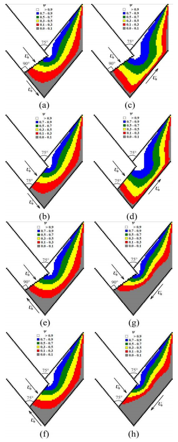 Figure 15. CFD-derived computational isolines of flow function ψ for the Segal die with channels' intersection angle 2θ = 75° for the rectangular punch AD–da (2θ0 = 90°) (a, c, e, g) and for the beveled inclined punch AD–da (2θ0 = 75°) (b, d, f, h), where Ⅰ) inlet die wall ab is a movable one with Vab
= U0; Vab↑↑U0; and outlet die wall bc is a fixed one with Vbc
= 0 (a, b); Ⅱ) inlet die wall ab is a fixed one with Vab = 0; and outlet die wall bc is a movable one with Vbc = U0; Vbc↑↑U0 (c, d); Ⅲ) inlet die wall ab is a movable one with Vab = U0; Vab↑↓U0; and outlet die wall bc is a fixed one with Vbc = 0 (e, f); and Ⅳ) inlet die wall ab is a fixed one with Vab
= 0; and outlet die wall bc is a movable one with Vbc
= U0; Vbc↑↓U0 (g, h).
Figure 15. CFD-derived computational isolines of flow function ψ for the Segal die with channels' intersection angle 2θ = 75° for the rectangular punch AD–da (2θ0 = 90°) (a, c, e, g) and for the beveled inclined punch AD–da (2θ0 = 75°) (b, d, f, h), where Ⅰ) inlet die wall ab is a movable one with Vab
= U0; Vab↑↑U0; and outlet die wall bc is a fixed one with Vbc
= 0 (a, b); Ⅱ) inlet die wall ab is a fixed one with Vab = 0; and outlet die wall bc is a movable one with Vbc = U0; Vbc↑↑U0 (c, d); Ⅲ) inlet die wall ab is a movable one with Vab = U0; Vab↑↓U0; and outlet die wall bc is a fixed one with Vbc = 0 (e, f); and Ⅳ) inlet die wall ab is a fixed one with Vab
= 0; and outlet die wall bc is a movable one with Vbc
= U0; Vbc↑↓U0 (g, h).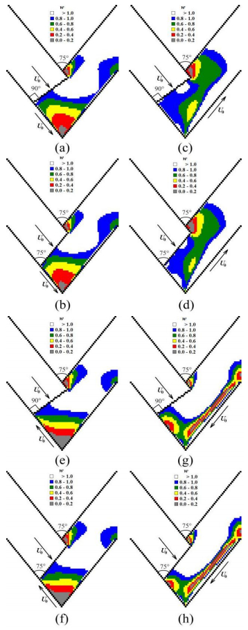 Figure 16. CFD-derived computational isolines of full flow velocity w for the Segal die with channels' intersection angle 2θ = 75° for the rectangular punch AD–da (2θ0 = 90°) (a, c, e, g) and for the beveled inclined punch AD–da (2θ0 = 75°) (b, d, f, h), where Ⅰ) inlet die wall ab is a movable one with Vab
= U0; Vab↑↑U0; and outlet die wall bc is a fixed one with Vbc
= 0 (a, b); Ⅱ) inlet die wall ab is a fixed one with Vab = 0; and outlet die wall bc is a movable one with Vbc = U0; Vbc↑↑U0 (c, d); Ⅲ) inlet die wall ab is a movable one with Vab = U0; Vab↑↓U0; and outlet die wall bc is a fixed one with Vbc = 0 (e, f); and Ⅳ) inlet die wall ab is a fixed one with Vab
= 0; and outlet die wall bc is a movable one with Vbc
= U0; Vbc↑↓U0 (g, h).
Figure 16. CFD-derived computational isolines of full flow velocity w for the Segal die with channels' intersection angle 2θ = 75° for the rectangular punch AD–da (2θ0 = 90°) (a, c, e, g) and for the beveled inclined punch AD–da (2θ0 = 75°) (b, d, f, h), where Ⅰ) inlet die wall ab is a movable one with Vab
= U0; Vab↑↑U0; and outlet die wall bc is a fixed one with Vbc
= 0 (a, b); Ⅱ) inlet die wall ab is a fixed one with Vab = 0; and outlet die wall bc is a movable one with Vbc = U0; Vbc↑↑U0 (c, d); Ⅲ) inlet die wall ab is a movable one with Vab = U0; Vab↑↓U0; and outlet die wall bc is a fixed one with Vbc = 0 (e, f); and Ⅳ) inlet die wall ab is a fixed one with Vab
= 0; and outlet die wall bc is a movable one with Vbc
= U0; Vbc↑↓U0 (g, h).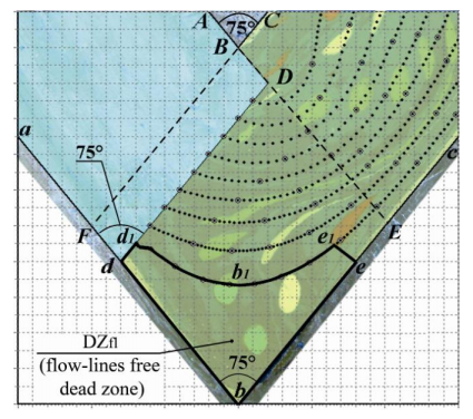 Figure 17. Comparison of experimentally-determined circular gridlines-based dead zone and the CFD-derived flow-lines-free dead zone DZfl (dbee1b1d1) in the case of ECAE through an acute-angle die with modified shape of 2θ0-inclined or 2θ0-beveled punch, where 2θ0 = 2θ = 75° < 90° and Vab
= Vbc = 0.
Figure 17. Comparison of experimentally-determined circular gridlines-based dead zone and the CFD-derived flow-lines-free dead zone DZfl (dbee1b1d1) in the case of ECAE through an acute-angle die with modified shape of 2θ0-inclined or 2θ0-beveled punch, where 2θ0 = 2θ = 75° < 90° and Vab
= Vbc = 0.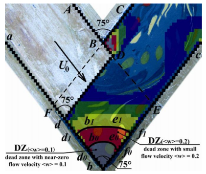 Figure 18. Comparison of experimentally-found circular gridlines-based dead zone and the CFD-derived dead zones DZ(<w> = 0.1) (bd0b0e0f0 with near-zero flow velocity <w> = 0.1) and DZ(<w> = 0.2) (bd1b1e1f1 with small flow velocity <w> = 0.2) in the case of ECAE through an acute-angle die with modified shape of 2θ0-inclined or 2θ0-beveled punch, where 2θ0 = 2θ = 75° < 90° and Vab = Vbc = 0.
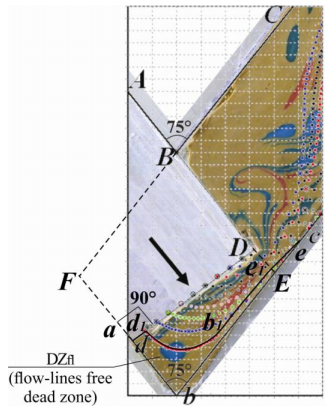 Figure 19. Comparison of experimentally-determined circular gridlines-based dead zone and the CFD-derived flow-lines-free dead zone DZfl (dbee1b1d1) at the final stage of ECAE-assisted deformation through an acute-angle die with classical punch of rectangular shape AD–da with 2θ0 = 90°, where 2θ = 75° < 90° and Vab = Vbc = 0.
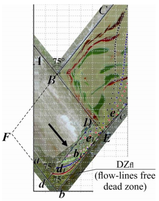 Figure 20. Comparison of experimentally-determined circular gridlines-based dead zone and the CFD-derived flow-lines-free dead zone DZfl (dbee1b1d1) at the final stage of ECAE-assisted deformation through an acute-angle die with modified shape of 2θ0-inclined or 2θ0-beveled punch, where 2θ0 = 2θ = 75° < 90° and Vab
= Vbc = 0.
Figure 20. Comparison of experimentally-determined circular gridlines-based dead zone and the CFD-derived flow-lines-free dead zone DZfl (dbee1b1d1) at the final stage of ECAE-assisted deformation through an acute-angle die with modified shape of 2θ0-inclined or 2θ0-beveled punch, where 2θ0 = 2θ = 75° < 90° and Vab
= Vbc = 0.The aim of physical simulation is an experimental study of dead zone abc formation and deformation zone abc location during viscous ECAE flow of workpiece plasticine models under the external action of rectangular and inclined punches in the case of the fixed motionless die walls with Vab = Vbc = 0. The physical simulation in Figures 1, 2, 17–20 is also focused on the experimental visualization of rotary modes of SPD during ECAE of viscous polymer models for the different punch geometries. The experimental results in Figures 1, 2, 17–20 are the original experimental research results, obtained by the authors.
The plastic die model of ECAE die ABC–abc with channel intersection angle ∠ABC = ∠abc = 2θ = 75° and the width of inlet aA–bB and outlet bB–cC die channels 35 mm is shown in Figures 1, 2, 17–20. Potato flour was used as the lubricator in Figures 1, 2, 17–20.
The main experimental visualization technique in Figures 1, 2, 17–20 is based on the manufacture of the initial plasticine physical models of the workpieces in the shapes of rectangular parallelepipeds, freezing of these rectangular parallelepipeds, marking the initial circular gridlines on the front sides of the frozen parallelepipeds, perforation of through-holes in the parallelepipeds at the centers of the initial circular gridlines, repeated freezing of the plasticine (Figures 1, 2, 17–20) parallelepipeds, heating of the plasticine (Figures 1, 2, 17–20) pieces with different colors to the half-solid state, and placing the half-solid multicolor plasticine (Figures 1, 2, 17–20) into the through-holes of the frozen parallelepipeds using a squirt without needle experimental physical simulation technique. In this way the initial plasticine-based (Figures 1, 2, 17–20) circular gridlines were marked throughout the initial plasticine (Figures 1, 2, 17–20) workpieces. The initial circular gridlines transform into deformed elliptical ones as workpieces flow from inlet to outlet die channels during ECAE (Figures 1(a), 1(c), 2, 17–20). The gridline-free dead zones (p. b) were visualized through the physical simulation techniques introduction in Figures 1, 2, 17–20. It was found that dead zone (p. b) formation takes place in the vicinity of the external angle abc of channel intersection zone Bb in the case of the fixed die walls with Vab = Vbc = 0.
It was experimentally shown that the best reduction of dead zone size (3) for an ECAE die with 2θ = 75° could be achieved through the replacement of the standard rectangular punch AD–ad with (2θ0 = 90°) in Figure 1(b) with the new 2θ0-inclined or 2θ0-beveled punch AD–ad with 2θ0 = 75° in the case of the fixed die walls with Vab = Vbc = 0 in Figure 1(c).
It was experimentally found in Figures 1, 2, 17–20 that the deformation zone BCDc during ECAE of viscous models is not located in the channel intersection zone Bb but is located in the beginning of the outlet die channel BC–bc in the case of the fixed die walls with Vab = Vbc = 0.
The relative location of the elliptical markers in outlet die channel BC–bc show the formation of two rotary modes of SPD during ECAE (Figures 1, 2, 17–20). Checking the successive locations of one color elliptical markers in Figures 1, 2, 17–20, we see that the major axis of every elliptical marker rotates with respect to the axis of the outlet die channel bc. We define the term of macroscopic rotation as the relative rotation of the major axis of an elliptical marker with respect to the flow direction axis bc. The macroscopic rotation is the first visually observable rotary mode during ECAE forming of viscous workpiece model. Visual comparison of Figures 1(b), 19 with Figures 1(a), 1(c), 2, 17, 18, 20 show that the macroscopic rotation is the unknown function of ECAE die channel intersection angle 2θ, punch shape 2θ0-geometry and transportation velocities of inlet ab and outlet cd external die walls. However under SPD ECAE treatment some deformed elliptical markers within the viscous material have additional bending points and have the form of "commas" or "tadpoles" in Figures 1, 2, 17–20. If the elliptical marker has the additional bending point during ECAE, then we will call the vicinity of the marker with this "waist" a zone of rotational inhomogeneity within the workpiece material, which is usually located at the beginning of the outlet die channel BC–bc in Figures 1, 2, 17–20. The rotational inhomogeneity is the second visually observable rotary mode during ECAE forming of the viscous workpiece model, which strongly depends on the ECAE die channel intersection angle 2θ, punch shape 2θ0-geometry and transport velocities of inlet ab and outlet cd external die walls.
The experimental results in Figures 1, 2, 17–20 have outlined the formation of the following zones within worked materials' volumes: (Ⅰ) the dead zone (p. b); (Ⅱ) the deformation zone BCDc; (Ⅲ) the macroscopic rotation zone (BC–bc), and (Ⅳ) the zone of rotational inhomogeneity (BC–bc). The complex of physical simulation techniques in Figures 1, 2, 17–20 introduces the initial circular gridlines technique with the application of plasticine workpieces with the initial circular colorful gridlines in the shape of initial colorful cylindrical plasticine inclusions (Figures 1, 2, 17–20). The application of the initial circular gridlines experimental techniques and the introduction of novel modified 2θ0-inclined or 2θ0-beveled punch shapes has not been addressed in previous known ECAE research [1,3,4,5,6,7,8,10,11,12,13,14,15,16,17,18,19,20,21,22,23,25,28,29,30].
The proposed complex of experimental techniques for physical simulation of SPD during ECAE in Figures 1, 2, 17–20 will find further applications in the study of viscous ECAE through dies with more complex Iwahashi, Luis-Perez, Utyashev, Conform and equal radii geometries with movable inlet and outlet die walls for the different punch shape 2θ0-geometries and different routes of multi-pass ECAE polymer working.
To use both dimensional and dimensionless values, we will mark dimensional values with overline symbols as is written in Nomenclature Chapter.
Navier-Stokes equations for x-and y-projections of dimensional velocities have the following form [9,26]:
| ∂ˉu∂ˉt+ˉu∂ˉu∂ˉx+ˉv∂ˉu∂ˉy=−1ˉρ⋅∂ˉp∂ˉx+ˉνvis⋅(∂2ˉu∂ˉx2+∂2ˉu∂ˉy2); | (1) |
| ∂ˉv∂ˉt+ˉu∂ˉv∂ˉx+ˉv∂ˉv∂ˉy=−1ˉρ⋅∂ˉp∂ˉy+ˉνvis⋅(∂2ˉv∂ˉx2+∂2ˉv∂ˉy2). | (2) |
In equations (1)–(2) and further the dimensional quantities are marked with overline symbols, i.e., with top underscores (see Nomenclature). Here we have two equations with three unknown functions u, v and punching pressure p. In order to close the system (1)–(2) we have to add the equation of continuity to the formulae (1)–(2):
| ∂ˉu∂ˉx+∂ˉv∂ˉy=0. | (3) |
The initial conditions for the system (1)–(3) have no basic importance because we study mainly the stationary solution of the system (1)–(3). For the derivation of the numerical solution in Figures 3–20, we transform system (1)–(3) and introduce the curl transfer equation in order to solve only one equation instead of the system (1)–(3). We will differentiate equation (1) with respect to y and equation (2) with respect to x. Then we will eliminate punching pressure p and define the dimensional curl function ˉζ as
| ˉζ=∂ˉu∂ˉy−∂ˉv∂ˉx. | (4) |
So we will have the following transfer equation for dimensional curl function ˉζ:
| ∂ˉζ∂ˉt=−ˉu∂ˉζ∂ˉx−ˉv∂ˉζ∂ˉy+ˉνvis⋅(∂2ˉζ∂ˉx2+∂2ˉζ∂ˉy2). | (5) |
In conservative form equation (5) is written as
| ∂ˉζ∂ˉt=−∂(ˉuˉζ)∂ˉx−∂(ˉvˉζ)∂ˉy+ˉνvis⋅(∂2ˉζ∂ˉx2+∂2ˉζ∂ˉy2). | (6) |
The conservative form of equation (6) implements the integral conservation laws, which are valid for the original equations (1)–(3).
We define the dimensional flow function ˉψ according to the following formulae:
| ∂ˉψ∂ˉy=ˉu;∂ˉψ∂ˉx=−ˉv. | (7) |
Equation (4) for the dimensional curl function may be written as:
| ∂2ˉψ∂ˉx2+∂2ˉψ∂ˉy2=ˉζ. | (8) |
The curl transfer equation (6) in dimensionless variables will have the following form:
| ∂ζ∂t=−Re(∂(uζ)∂x+∂(vζ)∂y)+(∂2ζ∂x2+∂2ζ∂y2), | (9) |
where the dimensionless curl function will be defined as:
| ζ=∂u∂y−∂v∂x. | (10) |
It is possible to write equations (9)–(10) in finite-difference form for further numerical integration according to the method of alternating directions for the cases of i↑j↑; i↓j↓; i↑j↓ and i↓j↑ (Figures 3–20). In finite difference form of equation (9), we will use upper indices (superscripts) near dimensionless functions ζ, ψ, u, v to denote the number of the time step and lower indices (subscripts) near dimensionless functions ζ, ψ, u, v to denote cell numbers, where the first subscript will mark cell numbers along the dimensionless abscissa x (Figures 3–20), and the second subscript will mark cell numbers along the dimensionless ordinate y (Figures 3–20). For the numerical simulation we define the inclined die wall with inclination angle θ, which diagonally crosses the cells of the computational grid.
Dimensional coordinate steps we will define as ˉξ=d(ˉx)=(1N)⋅ˉa⋅cos(θ) and ˉη=d(ˉy)=(1N)⋅ˉa⋅sin(θ).
Dimensionless coordinate steps we will define as ξ=ˉξˉa=d(ˉx)ˉa=(1N)⋅cos(θ) and η=ˉηˉa=d(ˉy)ˉa=(1N)⋅sin(θ).
If i↑,j↑, then
| ζn+1i,j={ζni,j−Re((uni+1,jζni+1,j−uni−1,jζni−1,j2ξ)+(vni,j+1ζni,j+1−vni,j−1ζni,j−12η))τ++((ζni+1,j−ζni,j+ζn+1i−1,jξ2)+(ζni,j+1−ζni,j+ζn+1i,j−1η2))τ}1{(1+(1ξ)2+(1η)2)τ}. | (11) |
If i↓,j↓, then
| n+1i,j={ζni,j−Re((uni+1,jζni+1,j−uni−1,jζni−1,j2ξ)+(vni,j+1ζni,j+1−vni,j−1ζni,j−12η))τ++((ζn+1i+1,j−ζni,j+ζni−1,jξ2)+(ζn+1i,j+1−ζni,j+ζni,j−1η2))τ}1{(1+(1ξ)2+(1η)2)τ}. | (12) |
If i↑,j↓, then
| ζn+1i,j={ζni,j−Re((uni+1,jζni+1,j−uni−1,jζni−1,j2ξ)+(vni,j+1ζni,j+1−vni,j−1ζni,j−12η))τ++((ζni+1,j−ζni,j+ζn+1i−1,jξ2)+(ζn+1i,j+1−ζni,j+ζni,j−1η2))τ}1{(1+(1ξ)2+(1η)2)τ}. | (13) |
If i↓,j↑, then
| ζn+1i,j={ζni,j−Re((uni+1,jζni+1,j−uni−1,jζni−1,j2ξ)+(vni,j+1ζni,j+1−vni,j−1ζni,j−12η))τ++((ζn+1i+1,j−ζni,j+ζni−1,jξ2)+(ζni,j+1−ζni,j+ζn+1i,j−1η2))τ}1{(1+(1ξ)2+(1η)2)τ}. | (14) |
Flow function ψ we find with Richardson iteration method as
| ψk+1i,j=12(1+β2)(ψki+1,j+ψki−1,j+β2ψki,j+1+β2ψki,j−1−ξ2ζi,j), | (15) |
where β=(ξη).
We now study the steady-state regime of viscous flow for a physical model of polymer material (Figures 3–20). So the initial conditions we will assume in the form of a rough approximation to the stationary solution (Figures 3–20):
| u0i,j=0;v0i,j=0;ζ0i,j=0;ψ0i,j=0. | (16) |
The boundary conditions for the die walls we will define as the viscous material "sticking" to the walls of the die (Figures 3–20). Material sticking condition means that material velocity has a zero value at the die wall surfaces.
The die wall is a flow line. Therefore the flow function is a constant along the whole length of a die wall. Equations (7) show that it is possible to satisfy an equation concerning unity value of dimensionless flow velocity for a unit dimensionless channel width by fulfillment the following condition for a flow function. The following dimensionless flow function rule for fluid flow in channels takes in account that, in the case of the unit dimensionless channel width and the unit dimensionless average flow velocity, the dimensionless flow function at the left flow boundary have to be greater by unity than at the right flow boundary. For the right die wall we may assume a zero value for the dimensionless flow function. Then, for the left die wall, we will get a unity value for the dimensionless flow function. Therefore we will assume that at the right and left flow boundaries the dimensionless flow functions are ψi,j=0 and ψi,j=1 in Table 1, respectively.
It is possible to systematize all necessary boundary conditions into a Table 1.
| Boundary | Boundary conditions |
| BC | u=0; v=0; ψ=1; ζi,j=(2⋅(ψi+1,j−1−ψi,j)(ξ2+η2)); |
| BD | u=sin(θ); v=−cos(θ); ψ=1; ζi,j=(2⋅(ψi+1,j+1−ψi,j+√ξ2+η2)(ξ2+η2)); |
| dD | u=sin(θ); v=−cos(θ); 0≤(ψfordD)≤1; ζ=0; |
| db | u=0; v=0; ψ=0; ζi,j=(2(ξ2+η2))⋅(ψi+1,j+1−ψi,j+(√ξ2+η2)⋅(VabU0)), where U0 is punch velocity (average flow velocity) and Vab is velocity of a movable die wall ab; |
| bc | u=0; v=0; ψ=0; ζi,j=(2(ξ2+η2))⋅(ψi−1,j+1−ψi,j+(√ξ2+η2)⋅(VbcU0)), where U0 is punch velocity (average flow velocity) and Vbc is velocity of a movable die wall bc; |
| cC | ψi,j=ψi−4,j−2⋅ψi−3,j+2⋅ψi−1,j; ζi,j=ζi−4,j−2⋅ζi−3,j+2⋅ζi−1,j; |
| points b, d | ψi,j=0; ζi,j=0; |
| point B | ψi,j=1; ζi,j=0; |
| point D(i, j) | for ζi+1,j we have ζi,j=2⋅(ψi+1,j−ψi,j)(ξ2); for ζi,j+1 we have ζi,j=2⋅(ψi,j+1−ψi,j)(η2). |
 DownLoad: CSV
Concerning dD, we can comment, that the local velocity at the whole length of the frontal punch edge dD is equal to the averaged flow velocity, which has a unity value. So the dimensionless flow function has to increase linearly along the punch length dD from zero value at point d(id, jd) to unit value at point D(iD, jD).
It is possible to derive the last boundary condition in Table 1 for the angular point D by series expansion of dimensionless flow function. For the point with coordinates (i, jw) lying on the horizontal boundary we have the following series expression
| ψi,jw+1=ψi,jw+(∂ψ∂y|i,jw)⋅Δy+(12)⋅(∂2ψ∂y2|i,jw)⋅(Δy)2+⋯. | (17) |
According to (7) and taking into account condition for adhesion of the viscous fluid we have the following expression
| ∂ψ∂y|i,jw=ui,jw=0. | (18) |
Moreover left hand side of (18) yields that
| ∂2ψ∂y2|i,jw=∂u∂y|i,jw. | (19) |
According to (10) the dimensionless curl function is defined as ζ = (∂u/∂y) – (∂v/∂x). Now let's take into account that at the wall we have
| v=const=0 | (20) |
Equations (10), (19) and (20) yield that
| ∂2ψ∂y2|i,jw=ζi,jw. | (21) |
So using (18) and (21) the series expression (17) yields that
| ζi,jw=2⋅(ψi,jw+1−ψi,jw)(Δy)2. | (22) |
We can now derive a generalized boundary condition in Table 1 for the curl function ζw at the inlet boundary by a series expansion of the flow function ψw+1 at the node, which is located one step away from the wall, measured normal to the wall. We can now write the following expression in the vicinity of the node point with a Taylor series expansion, analogous to (17):
| ψw+1=ψw+(∂ψ∂n|w)⋅Δn+(12)⋅(∂2ψ∂n2|w)⋅(Δn)2+⋯. | (23) |
No-slip condition and formulae (7) yield the following generalization of (18):
| ∂ψ∂n|w=uw=0. | (24) |
Moreover (8) yields the following generalization of (19):
| ∂2ψ∂n2|w=ζw. | (25) |
Substitution of (24) and (25) into (23) yields the following generalization of (22):
| ζw=2(ψw+1−ψw)(Δn)2. | (26) |
where Δn is the distance measured normal to the wall ranging from the nodal point w + 1 nearest to the wall to nodal point wall projection w. Therefore, it is possible to estimate the curl function expression at boundary (26) regardless of die wall orientation.
We can now derive the boundary conditions in Table 1 for the outlet boundary cC with the following Taylor series expansion:
| ψl=ψl−2+(ψl−1−ψl−2Δn)⋅2Δn+(ψl−2−2⋅ψl−3+ψl−4(2⋅Δn)⋅(2⋅Δn))⋅(2⋅Δn)2. | (27) |
Equation (27) yields the first equation for cC in Table 1:
| ψl=ψl−4−2⋅ψl−3+2⋅ψl−1. | (28) |
We can now derive the second equation for cC in Table 1 by making similar transformations, which are completely analogous to (27)–(28), attaining the following expression for the curl:
| ζl=ζl−4−2⋅ζl−3+2⋅ζl−1. | (29) |
The numerical results of integration curl transfer equations (9)–(15) with initial (16) and boundary (Table 1 and (17)–(29)) conditions are outlined in Figures 4–20 for the following numerical values:
| Parameter | Numerical Value | Comments and References |
| The dimensional width of inlet and outlet die channels | a = 35 (mm) | Figures 1–20 |
| The dimensional length of die channel | ˉL=16⋅ˉa=16×35×10−3(m);ˉL=0.56(m) | Figures 4–20 |
| The dimensional average ECAE punching velocity | ˉU0=0.1×10⁻³(m/s) | Figures 4–20 |
| The dimensional time of processed workpiece material motion in die channel | ˉt∗=ˉL/ˉU0;ˉt∗=(0.56m)/((0.1×10−3)(m/s));ˉt∗=5600(s) | Figures 4–20 |
| The maximum value of dimensionless curl | ζ=1 | Figures 4–20 |
| The dimensional curl | ˉζ=ζ⋅ˉU0/ˉa=(0.1×10−3(m/s))/(35×10−3(m));ˉζ=2.86×10−3(s−1) | Figures 4–20 |
| The dimensional average angular velocity of rotation for viscous material layers | ˉω=|rot→w|/2=ˉζ/2ˉω=1.43×10−3(s−1) | Figures 4–20 |
| The number of turns for viscous material layers during the time of workpiece material motion in die channel | N∗=ˉωˉt∗/2π=(1.43×10−3×5600)/(2×3.14);N∗=1.27 | Figures 4–20 |
| The dimensional density of the viscous plasticine physical model of extruded polymer material | ˉρ = 1850 (kg/m3) | Figures 1–20 |
| The dimensional plasticine yield strength | ˉσs = 217 (kPa) | Sofuoglu et al. [27] |
| The dimensional specific heat capacity of plasticine material | ˉc = 1.004 (kJ/(kg·K)) | Figures 1–20 |
| The dimensional thermal conductivity | ˉλ = 0.7 (J/(m·s·K)) | Chijiwa et al. [2] |
| The dimensional punching temperature | ˉttemp = 20 (℃) | Figures 1–20 |
| The dimensional dynamic viscosity for viscous Newtonian fluid model of plasticine workpiece during ECAE | ˉηvis = 1200 (kPa·s) | Figures 4–20 |
| The dimensional kinematic viscosity for viscous Newtonian fluid model of plasticine workpiece during ECAE | ˉνvis=ˉηvis/ˉρ;ˉνvis=(1.2×106/1850)(m2/s);ˉνvis=648.648(m2/s) | Figures 4–20 |
| Reynolds number | Re=ˉU0ˉaˉρ/ˉηvis;Re=ˉU0ˉa/ˉνvis;Re=5.396×10−9 | Figures 4–20 |
| The half number of coordinate steps along the x-and y-axes | N = 40 | Figures 4–20 |
| The number of coordinate steps along the x-and y-axes | 2N = 80 | Figures 4–20 |
| The relative error of iterations | e = 1/1000 | Figures 4–20 |
| The dimensional time moment for the first isochrone building | t1 = 100 (s) | Figures 4–20 |
| die channel intersection angle of Segal die | 2θ = 60° | Figures 4(a), 4(b), 7(a), 7(b), 10(a), 10(b) |
| 2θ = 75° | Figures 1, 2, 4(c), 4(d), 5, 7(c), 7(d), 8, 10(c), 10(d), 11, 14–20 | |
| 2θ = 90° | Figures 13(a), 13(b) | |
| 2θ = 105° | Figures 4(e), 4(f), 7(e), 7(f), 10(e), 10(f) | |
| 2θ = 120° | Figures 6(a), 6(b), 9(a), 9(b), 12(a), 12(b) | |
| 2θ = 135° | Figures 6(c), 6(d), 9(c), 9(d), 12(c), 12(d) | |
| punch shape inclination angle adD | 2θ0 = 60° | Figures 4(b), 7(b), 10(b) |
| 2θ0 = 75° | Figures 1(a), 1(c), 2, 4(d), 5(b), 7(d), 8(b), 10(d), 11(b), 14(b), 14(d), 14(f), 14(h), 15(b), 15(d), 15(f), 15(h), 16(b), 16(d), 16(f), 16(h), 17, 18, 20 | |
| 2θ0 = 90° | Figures 1(b), 4(a), 4(c), 4(e), 5(a), 6(a), 6(c), 7(a), 7(c), 7(e), 8(a), 9(a), 9(c), 10(a), 10(c), 10(e), 11(a), 12(a), 12(c), 13(a), 13(b), 14(a), 14(c), 14(e), 14(g), 15(a), 15(c), 15(e), 15(g), 16(a), 16(c), 16(e), 16(g), 19 | |
| 2θ0 = 105° | Figures 4(f), 7(f), 10(f) | |
| 2θ0 = 120° | Figures 6(b), 9(b), 12(b) | |
| 2θ0 = 135° | Figures 6(d), 9(d), 12(d) | |
| The dimensional horizontal and vertical coordinate steps along the x-and y-axes | ˉξ = 1.01 (mm) and ˉη 1.75 (mm) for ECAE die with 2θ = 60° | Figures 4(a), 4(b), 7(a), 7(b), 10(a), 10(b) |
| ˉξ = 1.10 (mm) and ˉη 1.44 (mm) for ECAE die with 2θ = 75° | Figures 1, 2, 4(c), 4(d), 5, 7(c), 7(d), 8, 10(c), 10(d), 11, 14–20 | |
| ˉξ = 1.24 (mm) and ˉη 1.24 (mm) for ECAE die with 2θ = 90° | Figures 13(a), 13(b) | |
| ˉξ = 1.44 (mm) and ˉη 1.10 (mm) for ECAE die with 2θ = 105° | Figures 4(e), 4(f), 7(e), 7(f), 10(e), 10(f) | |
| ˉξ = 1.75 (mm) and ˉη 1.01 (mm) for ECAE die with 2θ = 120° | Figures 6(a), 6(b), 9(a), 9(b), 12(a), 12(b) | |
| ˉξ = 2.286 (mm) and ˉη 0.947 (mm) for ECAE die with 2θ = 135° | Figures 6(c), 6(d), 9(c), 9(d), 12(c), 12(d) | |
| The dimensional time iteration step | ˉτ=ˉtit = 680 (μs) for ECAE die with 2θ = 60° | Figures 4(a), 4(b), 7(a), 7(b), 10(a), 10(b) |
| ˉτ=ˉtit = 610 (μs) for ECAE die with 2θ = 75° | Figures 1, 2, 4(c), 4(d), 5, 7(c), 7(d), 8, 10(c), 10(d), 11, 14–20 | |
| ˉτ=ˉtit = 590 (μs) for ECAE die with 2θ = 90° | Figures 13(a), 13(b) | |
| ˉτ=ˉtit = 610 (μs) for ECAE die with 2θ = 105° | Figures 4(e), 4(f), 7(e), 7(f), 10(e), 10(f) | |
| ˉτ=ˉtit = 680 (μs) for ECAE die with 2θ = 120° | Figures 6(a), 6(b), 9(a), 9(b), 12(a), 12(b) | |
| ˉτ=ˉtit = 830 (μs) for ECAE die with 2θ = 135° | Figures 6(c), 6(d), 9(c), 9(d), 12(c), 12(d) | |
| The dimensional transition time | ˉt = 12.6 (s) for ECAE die with 2θ = 60° | Figures 4(a), 4(b), 7(a), 7(b), 10(a), 10(b) |
| ˉt = 11.3 (s) for ECAE die with 2θ = 75° | Figures 1, 2, 4(c), 4(d), 5, 7(c), 7(d), 8, 10(c), 10(d), 11, 14–20 | |
| ˉt = 10.9 (s) for ECAE die with 2θ = 90° | Figures 13(a), 13(b) | |
| ˉt = 11.3 (s) for ECAE die with 2θ = 105° | Figures 4(e), 4(f), 7(e), 7(f), 10(e), 10(f) | |
| ˉt = 12.6 (s) for ECAE die with 2θ = 120° | Figures 6(a), 6(b), 9(a), 9(b), 12(a), 12(b) | |
| ˉt = 15.5 (s) for ECAE die with 2θ = 135° | Figures 6(c), 6(d), 9(c), 9(d), 12(c), 12(d) |
DownLoad: CSVIn order to derive the mathematical model of viscous material flow during ECAE through a non-rectangular Segal 2θ-die taking into account the punch shape AD–ad effect on viscous flow dynamics we will apply the Navier-Stokes equations (1)–(29) and Table 1. The results of the numerical simulation study are shown in Table 2 and in computational diagrams in Figures 4–20.
Computational results in Figures 4–20 illustrate punch shape influence on geometry (Figures 4–6, 14, 17, 19, 20), kinematics (Figures 10–12, 13(b), 16, 18) and dynamics (Figures 7–9, 13(a), 15) of the viscous flow during ECAE. Computational plots in Figures 4–20 are based on a finite-difference solution (11)–(15) of Navier-Stokes equations (1)–(3) in curl transfer form (4)–(10) with initial (16) and boundary (Table 1 & (17)–(29)) conditions.
Instabilities of the numerical solutions, which appear at the outlet frontiers cC (Figures 4–20), propagate upstream.
The numerical solution (Figures 4(c), 4(d), 5, 7(c), 7(d), 8, 10(c), 10(d), 11, 14–20) for the ECAE through the die with 2θ = 75° satisfactorily agrees with the physical simulation results (Figures 1, 2, 17–20) only when the outputs cC of viscous flows are located well away from channel intersection bisector bB, i.e., ideally the channel outputs cC have to be infinitely distant from bisector bB. So the finite difference grid cells near the outputs cC for i > 30 were rejected from the plots in Figures 4–20.
CFD-derived computational flow lines in Figures 4–6, 14, 17, 19, 20 and full flow velocities in Figures 10–12, 13(b), 16, 18 directly show the formation of shear stress-free dead zone areas dDbc during ECAE of viscous continuum through the acute-angled Segal 2θ-dies with 2θ < 90°.
CFD-derived computational flow lines in Figures 4–6, 14, 17, 19–20 and full flow velocities in Figures 10–12, 13(b), 16, 18 outline the reduction of dead zone areas dDbc when we use the modified 2θ0-inclined or 2θ0-beveled punch shapes (Figures 4(b), 4(d), 4(f), 5(b), 6(b), 6(d), 7(b), 7(d), 7(f), 8(b), 9(b), 9(d), 10(b), 10(d), 10(f), 11(b), 12(b), 12(d), 14(b), 14(d), 14(f), 14(h), 15(b), 15(d), 15(f), 15(h), 16(b), 16(d), 16(f), 16(h), 17, 18, 20) with 2θ0 = 2θ.
CFD-derived computational flow lines in Figures 4–6, 14, 17, 19–20 and full flow velocities in Figures 10–12, 13(b), 16, 18 also outline the largest dead zone areas dDbc when we use the standard punch (Figures 4(a), 4(c), 4(e), 5(a), 6(a), 6(c), 7(a), 7(c), 7(e), 8(a), 9(a), 9(c), 10(a), 10(c), 10(e), 11(a), 12(a), 12(c), 13(a), 13(b), 14(a), 14(c), 14(e), 14(g), 15(a), 15(c), 15(e), 15(g), 16(a), 16(c), 16(e), 16(g), 19) with standard rectangular shape (2θ0 = 90°).
CFD-derived computational flow lines in Figures 14(a), 14(b), flow functions in Figures 15(a), 15(b), and full flow velocities in Figures 16(a), 16(b) show significant sharpening and reduction of dead zone areas dDbc because of shifting of flow lines to movable inlet die wall ab when inlet die wall ab moves parallel to the viscous flow Vab↑↑U0 with velocity Vab = U0, and outlet die wall bc is a fixed one with Vbc = 0 during ECAE of viscous continuum through the acute-angled Segal 2θ-dies with 2θ < 90°.
CFD-derived computational flow lines in Figures 14(c), 14(d), flow functions in Figures 15(c), 15(d), and full flow velocities in Figures 16(c), 16(d) directly show complete vanishing and disappearance of dead zone areas dDbc when inlet die wall ab is a fixed one with Vab = 0; and outlet die wall bc is a movable one and bc moves parallel to the viscous flow Vbc↑↑U0 with Vbc = U0 during ECAE of viscous continuum through the acute-angled Segal 2θ-dies with 2θ < 90°.
CFD-derived computational flow lines in Figures 14(e), 14(f), flow functions in Figures 15(e), 15(f), and full flow velocities in Figures 16(e), 16(f) show significant enhancement and broadening of dead zone areas dDbc because of shifting of flow lines from movable inlet die wall ab when inlet die wall ab moves anti-parallel to the viscous flow Vab↑↓U0 with velocity Vab = U0, and outlet die wall bc is a fixed one with Vbc = 0 during ECAE of viscous continuum through the acute-angled Segal 2θ-dies with 2θ < 90°.
CFD-derived computational flow lines in Figures 14(g), 14(h), flow functions in Figures 15(g), 15(h), and full flow velocities in Figures 16(g), 16(h) outline formation of macroscopic rotation zone with significant mixing of viscous material in vicinity of the external outlet die wall bc when inlet die wall ab is a fixed one with Vab = 0; and outlet die wall bc is a movable one and bc moves anti-parallel to the viscous flow Vbc↑↓U0 with Vbc = U0 during ECAE of viscous continuum through the acute-angled Segal 2θ-dies with 2θ < 90°.
It is possible to provide experimental verification of CFD-derived results in Figure 17 by comparing the dead zone areas through making an additional superposition of the physical simulation-based result in Figure 1(a) with CFD-developed flow lines in Figure 4(d). Figure 17 illustrates the first geometric hypothesis that the symmetrical dead zone of ECAE-worked material is the flow-lines-free dead zone DZfl (dbee1b1d1). This first hypothesis is supported by the empirically-determined location of three almost undeformed markers with nearly circular shapes within the flow-lines-free dead zone area (dbee1b1d1).
The relative area ˉA(dbee1b1d1) of dead zone DZfl in Figure 17 can be determined as a ratio of the area A(dbee1b1d1) of dead zone (dbee1b1d1) to the area A(FbEB) of the deformation region (FbEB):
| ˉA(dbee1b1d1)=A(dbee1b1d1)A(FbEB). | (30) |
Application of formula (30) to Figure 17 yields that ˉA(dbee1b1d1)≈0.29≈0.3≈30% or A(dbee1b1d1)≈0.3⋅A(FbEB)≈30%⋅A(FbEB). Therefore the first hypothesis, concerning the coincidence of the material dead zone with the flow-lines-free region results in a numerical value 30% for the relative area of the dead zone with respect to the area of the deformation region in the channel intersection zone. The result of superposition in Figure 17 shows that the first hypothesis is valid because the dead zone (dbee1b1d1) contains 3 visually-observable slightly-deformed almost circular markers. Therefore Figure 17 shows a good agreement between the experimental result in Figure 1(a) and the theoretical result in Figure 4(d).
It is also possible to provide experimental verification of the CFD-derived results in Figure 18 by comparing dead zone areas through making an additional superposition of physical simulation-based results in Figure 1(a) with CFD-derived dimensionless full flow velocities w in Figure 10(d). Figure 18 illustrates the second geometric hypothesis that the nearly symmetrical dead zone of ECAE-worked material coincides with the larger dead zone DZ(<w> = 0.1) (bd0b0e0f0 with near-zero flow velocity <w> = 0.1) or with smaller dead zone DZ(<w> = 0.2) (bd1b1e1f1 with small flow velocity <w> = 0.2). This second hypothesis is supported by the empirically-determined location of three barely deformed markers with nearly circular shapes within the larger dead zone area DZ(<w> = 0.2) (bd1b1e1f1 with small flow velocity <w> = 0.2) and appearance of one circle marker near to corner b within smaller dead zone area DZ(<w> = 0.1) (bd0b0e0f0 with near-zero flow velocity <w> = 0.1) in Figure 18.
The relative area ˉA(bd0b0e0f0) of the smaller dead zone DZ(<w> = 0.1) in Figure 18 can be determined as a ratio of the area A(bd0b0e0f0) of the smaller dead zone (bd0b0e0f0) to the area A(FbEB) of the deformation region (FbEB):
| ˉA(bd0b0e0f0)=A(bd0b0e0f0)A(FbEB). | (31) |
Application of formula (31) to the smaller dead zone DZ(<w> = 0.1) in Figure 18 yields that ˉA(bd0b0e0f0)≈0.083≈8.3% or A(bd0b0e0f0)≈0.083⋅A(FbEB)≈8.3%⋅A(FbEB).
The relative area ˉA(bd1b1e1f1) of the larger dead zone DZ(<w> = 0.2) in Figure 18 can be determined as a ratio of the area A(bd1b1e1f1) of the larger dead zone (bd1b1e1f1) to the area A(FbEB) of the deformation region (FbEB):
| ˉA(bd1b1e1f1)=A(bd1b1e1f1)A(FbEB). | (32) |
Application of formula (32) to the larger dead zone DZ(<w> = 0.2) in Figure 18 yields that ˉA(bd1b1e1f1)≈0.2084≈0.21≈21% or A(bd1b1e1f1)≈0.21⋅A(FbEB)≈21%⋅A(FbEB).
Therefore the second hypothesis concerning the coincidence of the material dead zone with the flow-velocity-free smaller region DZ(<w> = 0.1) or with small flow velocities larger region DZ(<w> = 0.2) results in the numerical values 8.3% and 21% for the relative areas of smaller and larger dead zones with respect to area of deformation region in channel intersection zone. The result of superposition in Figure 18 shows that the second hypothesis is also valid because the larger dead zone (bd1b1e1f1) contains 3 visually-observable slightly-deformed almost circular markers and the smaller dead zone (bd0b0e0f0) contains 1 non-deformed circular marker. Therefore Figure 18 shows a good agreement between the experimental result in Figure 1(a) and the theoretical result in Figure 10(d).
It is possible to provide experimental verification of CFD-derived results in Figure 19 by comparing the dead zone areas through making an additional superposition of the physical simulation-based result in Figure 1(b) with CFD-developed flow lines in Figure 5(a) at the final stage of ECAE-assisted deformation. Figure 19 illustrates the first geometric hypothesis that the non-symmetrical dead zone of ECAE-worked material is the flow-lines-free dead zone DZfl (dbee1b1d1), located in the lower corner b of an acute-angle die with 2θ = 75° < 90° after material deformation with classical punch of rectangular shape AD–da with 2θ0 = 90°. This first hypothesis is supported by the empirically-determined location of one large almost undeformed dark blue color marker with nearly circular shape within the flow-lines-free dead zone area (dbee1b1d1).
The relative area ˉA(dbee1b1d1) of dead zone DZfl in Figure 19 can be determined with formula (30) as a ratio of the area A(dbee1b1d1) of dead zone (dbee1b1d1) to the area A(FbEB) of the deformation region (FbEB). Application of formula (30) to Figure 19 yields that ˉA(dbee1b1d1)≈0.123≈0.125≈12.5% or A(dbee1b1d1)≈0.125⋅A(FbEB)≈12.5%⋅A(FbEB). Therefore the first hypothesis, concerning the coincidence of the material dead zone with the flow-lines-free region results in a numerical value 12.5% for the relative area of the dead zone with respect to the area of the deformation region in the channel intersection zone. The result of superposition in Figure 19 shows that the first hypothesis is valid because the dead zone (dbee1b1d1) partially contains one visually-observable slightly-deformed almost circular marker, located near to lower corner b. Therefore Figure 19 shows a good agreement between the experimental result in Figure 1(b) and the theoretical result in Figure 5(a).
It is possible to provide experimental verification of CFD-derived results in Figure 20 by comparing the dead zone areas through making an additional superposition of the physical simulation-based result in Figure 1(c) with CFD-developed flow lines in Figure 5(b) at the final stage of ECAE-assisted deformation through an acute-angle die with modified shape of 2θ0-inclined or 2θ0-beveled punch, where 2θ0 = 2θ = 75° < 90°. Figure 20 illustrates the first geometric hypothesis that the non-symmetrical dead zone of ECAE-worked material is the flow-lines-free dead zone DZfl (dbee1b1d1), located under the inclined punch. Application of formula (30) to Figure 20 yields that ˉA(dbee1b1d1)≈0.07≈7% or A(dbee1b1d1)≈0.07⋅A(FbEB)≈7%⋅A(FbEB). Therefore the first hypothesis, concerning the coincidence of the material dead zone with the flow-lines-free region results in a numerical value 7% for the relative area of the dead zone with respect to the area of the deformation region in the channel intersection zone. The result of superposition in Figure 20 shows that the first hypothesis is valid because the relative area of dead zone 7% in Figure 20 is smaller than the relative area of dead zone 12.5% in Figure 19. Therefore Figure 20 shows a good agreement between the experimental result in Figure 1(c) and the theoretical result in Figure 5(b).
The technological problem addressed in this article has direct industrial importance in material pressure forming applications. The introduction of the fluid dynamics numerical simulation provides us with a better understanding of physical simulation results in Figures 1, 2, 17–20.
Experimental comparison of physical simulation experiments and CFD-derived numerical results was done through a geometric comparison of the dead zone areas in additional Figures 17–20.
It was found with two hypotheses that the relative area of the material dead zone with respect to the area of the deformation zone in the channel intersection region has a value from 8.3% to 21% in Figure 18 and a value of 30% in Figure 17. Therefore it is possible to estimate the relative area of the material dead zone as the value in the range of 20–26% of the deformation zone area, which is in good agreement with the visually-observable location of three almost non-deformed elliptical markers in the lower corner of the material deformation zone in Figures 17–18.
It was found with the first hypothesis that the relative area of the material dead zone with respect to the area of the deformation zone in the channel intersection region has a value from 9.6% to 12.5% in Figure 19 and a value of 7% in Figure 20. Therefore it is possible to estimate the relative area of the material dead zone as the value in the range of 7–12.5% of the deformation zone area, which is in good agreement with the visually-observable location of the material deformation zone at the final stage of ECAE-assisted deformation in Figures 19–20.
When we analyze the computational CFD-derived Figures 4–20, we find that in order for a viscous material to become a yielding material, it is necessary to apply all-round uniform hydrostatic compression until internal yield pressure is reached. Then it is necessary to create a longitudinal pressure gradient for rectilinear forward translatory motion of viscous continuum and a transverse pressure gradient in order to change the direction of motion of the viscous material in the curved channel intersection zone. The normal component of the pressure force of punch surface front dD causes the formation of an all-round uniform hydrostatic compression and a longitudinal pressure gradient. The tangential component of the pressure force of the punch surface front dD causes the formation of a transverse pressure gradient.
The novel modified 2θ0-inclined or 2θ0-beveled punch is completely identical to the standard classical punch with 2θ0 = 90° for ECAE of viscous continuum through the angular die with channel intersection angle 2θ = 90° as is shown in Figure 13.
CFD simulation in Figures 14–16 allowed to identify the following two technologically favorable kinematic cases, shown in Figures 14(a–d), 15(a–d), 16(a–d).
It was outlined in Figures 14(a), 14(b), 15(a), 15(b), 16(a), 16(b) that it is possible to achieve significant sharpening and reduction of dead zone areas dDbc because of shifting of flow lines to movable inlet die wall ab when inlet die wall ab moves parallel to the viscous flow Vab↑↑U0 with velocity Vab = U0, and outlet die wall bc is a fixed one with Vbc = 0 during ECAE of viscous continuum through the acute-angled Segal 2θ-dies with 2θ < 90°. This is the first kinematically sound case for dead zone minimization during polymer ECAE realization.
It was found in Figures 14(c), 14(d), 15(c), 15(d), 16(c), 16(d) that it is possible to achieve complete vanishing and disappearance of dead zone areas dDbc when inlet die wall ab is a fixed one with Vab = 0; and outlet die wall bc is a movable one and bc moves parallel to the viscous flow Vbc↑↑U0 with Vbc = U0 during ECAE of viscous continuum through the acute-angled Segal 2θ-dies with 2θ < 90°. This is the second recommended case for dead zone reduction.
The most intensive case for generation of enhanced and large rotational modes of severe plastic deformation during ECAE corresponds to Figures 14(g), 14(h), 15(g), 15(h), 16(g), 16(h) and outlines formation of macroscopic rotation zone with significant mixing of viscous material in vicinity of the external outlet die wall bc when inlet die wall ab is a fixed one with Vab = 0; and outlet die wall bc is a movable one and bc moves anti-parallel to the viscous flow Vbc↑↓U0 with Vbc = U0 during ECAE of viscous continuum through the acute-angled Segal 2θ-dies with 2θ < 90°. This is the most severe kinematical case with no dead zone formation, suited for highly intensive pressure forming of non-brittle polymer workpieces.
Technologically saying, the worst ECAE case with formation of largest dead zone is shown in Figures 14(e), 14(f), 15(e), 15(f), 16(e), 16(f). This kinematical case produces significant enhancement and broadening of dead zone areas dDbc because of shifting of flow lines from movable inlet die wall ab when inlet die wall ab moves anti-parallel to the viscous flow Vab↑↓U0 with velocity Vab = U0, and outlet die wall bc is a fixed one with Vbc = 0 during ECAE of viscous continuum through the acute-angled Segal 2θ-dies with 2θ < 90°. This kinematical case of ECAE pressure forming is surely not recommended on dead zone growth.
In the present work we addressed the technological problem of the kinematic effects of punch shape geometry and movable inlet and outlet die wall motion on material flow dynamics during ECAE through the numerical solution of the boundary value problem ((1)–(29) & Table 1) for Navier-Stokes equations in curl transfer form (Figures 4–20), taking into account the independent alternating transport motion of the inlet and outlet die walls as well as the standard rectangular and improved 2θ0-inclined or 2θ0-beveled punch shapes.
CFD-derived flow lines (Figure 14) show significant reduction of dead zone areas when the inlet die wall is fixed and the outlet die wall is movable and moves parallel to the viscous flow during ECAE of viscous continuum through the acute-angled Segal 2θ-dies with 2θ < 90°.
Computational flow lines (Figure 14) outline the formation of a macroscopic rotation zone with significant mixing of viscous material in the vicinity of the external outlet die wall with minimization of dead zone area when the inlet die wall is fixed and the outlet die wall is movable and it moves anti-parallel to the viscous flow.
CFD-derived flow lines (Figure 14) show significant sharpening and reduction of dead zone areas because of shifting of flow lines to the movable inlet die wall when the inlet die wall moves parallel to the viscous flow and the outlet die wall is fixed.
CFD-derived flow lines (Figure 14) show significant enhancement and broadening of dead zone areas because of shifting of flow lines from the movable inlet die wall when the inlet die wall moves anti-parallel to the viscous flow and the outlet die wall is fixed one.
Both physical (Figures 1(b), 19) and CFD (Figures Figures 4(a), 4(c), 4(e), 5(a), 6(a), 6(c), 7(a), 7(c), 7(e), 8(a), 9(a), 9(c), 10(a), 10(c), 10(e), 11(a), 12(a), 12(c), 14(a), 14(c), 14(e), 14(g), 15(a), 15(c), 15(e), 15(g), 16(a), 16(c), 16(e), 16(g), 19) simulations show that the application of a standard rectangular punch with 2θ0 = 90° for workpiece ECAE through acute-angled Segal 2θ-dies with 2θ < 90° and obtuse-angled Segal 2θ-dies with 2θ > 90° is highly undesirable because of the resulting large material dead zone areas dDb in the neighborhood of the external die angle 2θ = ∠(abc).
Both physical (Figures 1(a), 1(c), 2, 17, 18, 20) and CFD (Figures 4(b), 4(d), 4(f), 5(b), 6(b), 6(d), 7(b), 7(d), 7(f), 8(b), 9(b), 9(d), 10(b), 10(d), 10(f), 11(b), 12(b), 12(d), 14(b), 14(d), 14(f), 14(h), 15(b), 15(d), 15(f), 15(h), 16(b), 16(d), 16(f), 16(h), 17, 18, 20) simulations reveal that the introduction of 2θ0-inclined or 2θ0-beveled punch shapes with 2θ0 = 2θ and dD||bc for material ECAE processing through the acute-angled Segal 2θ-dies with 2θ < 90°, and obtuse-angled Segal 2θ-dies with 2θ > 90° is a very promising technique because of minimal material dead zone areas dDb and the resulting minimal material waste in the neighborhood of external die angle 2θ = ∠(abc), e.g., for 2θ = 75° (Figures 1, 2, 4(c), 4(d), 5, 7(c), 7(d), 8, 10(c), 10(d), 11, 14–20).
The proposed CFD-based simulation of viscous material SPD during ECAE in Figures 4–20 will find further applications in the study of viscous ECAE through dies with more complex Iwahashi, Luis-Perez, Utyashev, Conform and equal radii geometries with movable inlet and outlet die walls for the different punch shape 2θ0-geometries and different routes of multi-pass ECAE polymer working by pressure.
Authors thank "anonymous" referees for their valuable notes and suggestions.
The authors Alexander V. Perig and Nikolai N. Golodenko declare that there is no conflict of interests regarding the publication of this paper. The authors declare that they have no competing interests.
| [1] |
Beloshenko VA, Voznyak YV, Reshidova IY, et al. (2013) Equal-channel angular extrusion of polymers. J Polym Res 20: 322. doi: 10.1007/s10965-013-0322-2

|
| [2] |
Chijiiwa K, Hatamura Y, Hasegawa N (1981) Characteristics of plasticine used in the simulation of slab in rolling and continuous casting. T Iron Steel I Jpn 21: 178–186. doi: 10.2355/isijinternational1966.21.178
|
| [3] | Koutcheryaev BV (2000) Modeling of continual flows in angular domains, in: Lowe TC, Valiev RZ, Investigations and Applications of Severe Plastic Deformation, NATO Science Series (Series 3. High Technology), Dordrecht: Springer, 80: 37–42. |
| [4] | Kucheryaev BV (2006) Mekhanika sploshnykh sred (teoreticheskie osnovy obrabotki davleniem kompozitnykh metallov s zadachami i resheniiami, primerami i uprazhneniiami) [Continuum mechanics (Theoretical principles of the pressure treatment of composite metals with problems and solutions, examples and exercises)], 2 Eds., Moscow: MISiS (in Russian). |
| [5] | Laptev AM, Perig AV, Vyal OY (2014) Analysis of equal channel angular extrusion by upper bound method and rigid blocks model. Mater Res-Ibero-Am J 17: 359–366. |
| [6] | Minakowski P (2014) Fluid model of crystal plasticity: numerical simulations of 2-turn equal channel angular extrusion. Technische Mechanik 34: 213–221. |
| [7] |
Nejadseyfi O, Shokuhfar A, Azimi A (2015) Improving homogeneity of ultrafine-grained/nanostructured materials produced by ECAP using a bevel-edge punch. J Mater Sci 50: 1513–1522. doi: 10.1007/s10853-014-8712-3
|
| [8] |
Nejadseyfi O, Shokuhfar A, Sadeghi S (2016) Feasibility of attaining uniform grain structure and enhanced ductility in aluminum alloy by employing a beveled punch in equal-channel angular pressing. Mat Sci Eng A-Struct 651: 461–466. doi: 10.1016/j.msea.2015.08.050
|
| [9] | Oswald P (2009) Rheophysics: The deformation and flow of matter, New York: Cambridge University Press. |
| [10] |
Perig AV, Laptev AM, Golodenko NN, et al. (2010) Equal channel angular extrusion of soft solids. Mat Sci Eng A-Struct 527: 3769–3776. doi: 10.1016/j.msea.2010.03.043
|
| [11] | Perig AV, Zhbankov IG, Palamarchuk VA (2013) Effect of die radii on material waste during equal channel angular extrusion. Mater Manuf Process 28: 910–915. |
| [12] | Perig AV, Zhbankov IG, Matveyev IA, et al. (2013) Shape effect of angular die external wall on strain unevenness during equal channel angular extrusion. Mater Manuf Process 28: 916–922. |
| [13] |
Perig AV, Laptev AM (2014) Study of ECAE mechanics by upper bound rigid block model with two degrees of freedom. J Braz Soc Mech Sci 36: 469–476. doi: 10.1007/s40430-013-0121-z
|
| [14] |
Perig AV, Golodenko NN (2014) CFD simulation of ECAE through a multiple-angle die with a movable inlet wall. Chem Eng Commun 201: 1221–1239. doi: 10.1080/00986445.2014.894509
|
| [15] |
Perig AV, Golodenko NN (2014) CFD 2D simulation of viscous flow during ECAE through a rectangular die with parallel slants. Int J Adv Manuf Tech 74: 943–962. doi: 10.1007/s00170-014-5827-2
|
| [16] | Perig AV (2014) 2D upper bound analysis of ECAE through 2θ-dies for a range of channel angles. Mater Res-Ibero-Am J 17: 1226–1237. |
| [17] |
Perig AV, Tarasov AF, Zhbankov IG, et al. (2015) Effect of 2θ-punch shape on material waste during ECAE through a 2θ-die. Mater Manuf Process 30: 222–231. doi: 10.1080/10426914.2013.832299
|
| [18] |
Perig AV, Golodenko NN (2015) ECAP process improvement based on the design of rational inclined punch shapes for the acute-angled Segal 2θ-dies: CFD 2-D description of dead zone reduction. Mech Sci 6: 41–49. doi: 10.5194/ms-6-41-2015
|
| [19] | Perig A (2015) Two-parameter rigid block approach to upper bound analysis of equal channel angular extrusion through a Segal 2θ-die. Mater Res-Ibero-Am J 18: 628–638. |
| [20] | Perig AV, Golodenko NN (2016) CFD 2D description of local flow of polymer workpiece through a modified U-shaped die during equal channel multiple angular extrusion. Mater Res-Ibero-Am J 19: 602–610. |
| [21] |
Perig AV, Golodenko NN (2016) Effect of workpiece viscosity on strain unevenness during equal channel angular extrusion: CFD 2D solution of Navier-Stokes equations for the physical variables 'flow velocities–punching pressure'. Mater Res Express 3: 115301. doi: 10.1088/2053-1591/3/11/115301
|
| [22] | Perig AV, Golodenko NN (2017) Effects of material rheology and die walls translational motions on the dynamics of viscous flow during equal channel angular extrusion through a Segal 2θ-die: CFD 2D solution of a curl transfer equation. Adv Mater Sci Eng 2017: 7015282. |
| [23] |
Perig AV, Galan IS (2017) The experimental verification of the known flow line models describing local flow during ECAE (ECAP). Lett Mater 7: 209–217. doi: 10.22226/2410-3535-2017-3-209-217
|
| [24] | Popov VL, Slyadnikov EE (1995) Plastic distortion vortices in solids under intense external action. Tech Phys Lett+ 21: 81–82. |
| [25] |
Rejaeian M, Aghaie-Khafri M (2014) Study of ECAP based on stream function. Mech Mater 76: 27–34. doi: 10.1016/j.mechmat.2014.05.004
|
| [26] | Roache PJ (1976) Computational Fluid Dynamics, Albuquerque: Hermosa Publishers. |
| [27] |
Sofuoglu H, Rasty J (2000) Flow behavior of Plasticine used in physical modeling of metal forming processes. Tribol Int 33: 523–529. doi: 10.1016/S0301-679X(00)00092-X
|
| [28] |
Tabatabaei SA, Abrinia K, Tabatabaei SM, et al. (2015) Analytical modeling of the extrusion process using the electrostatics concept. Mech Mater 88: 87–102. doi: 10.1016/j.mechmat.2015.03.007
|
| [29] |
Tóth LS, Massion RA, Germain L, et al. (2004) Analysis of texture evolution in equal channel angular extrusion of copper using a new flow field. Acta Mater 52: 1885–1898. doi: 10.1016/j.actamat.2003.12.027
|
| [30] | Wei K, Liu P, Ma Z, et al. (2015) An upper bound analysis of T-shaped equal channel angular pressing. Acta Metall Slovaca 21: 4–12. |
| 1. | Pavlo A. Gavrish, Mikhail A. Turchanin, Alexander V. Perig, Analysis of the reasons for the penetration of copper into steel during welding, 2020, 2374-068X, 1, 10.1080/2374068X.2020.1801252 | |
| 2. | Alexander V. Perig, Anatoliy V. Zavdoveev, Violetta M. Skyrtach, Oleksii D. Kovalov, Boshra A. Arnout, Vuk Uskoković, Pavlo A. Gavrish, Oleh D. Hanevych, Bohdan Yu. Sharapaniuk, Alexander A. Kostikov, Oleg V. Subotin, Materials extrusion-inspired engineering reflection of social pressure-induced environmental impact on academy community well-being, 2021, 68, 10519815, 333, 10.3233/WOR-203301 | |
| 3. | Alexander V. Perig, Nikolai N. Golodenko, CFD-enhanced description of local viscous flow through expansion equal channel angular extrusion geometric domain, 2019, 5, 2374-068X, 617, 10.1080/2374068X.2019.1666502 | |
| 4. | Pavlo A. Gavrish, Alexander V. Perig, Improvement of the heat state in welding copper with steel, 2020, 6, 2374-068X, 703, 10.1080/2374068X.2020.1782086 | |
| 5. | Anastasiia V. Liuta, Alexander V. Perig, Marharyta A. Afanasieva, Violetta M. Skyrtach, Didactic games as student-friendly tools for learning hydraulics in a technical university’s undergraduate curriculum, 2019, 33, 0950-4222, 198, 10.1177/0950422218824507 |


Figures(20) / Tables(2)

Alexander V. Perig, Nikolai N. Golodenko. 2D CFD description of the kinematic effects of movable inlet and outlet die wall transport motion and punch shape geometry on the dynamics of viscous flow during ECAE through Segal 2θ-dies for a range of channel angles[J]. AIMS Materials Science, 2017, 4(6): 1240-1275. doi: 10.3934/matersci.2017.6.1240

| Boundary | Boundary conditions |
| BC | u=0; v=0; ψ=1; ζi,j=(2⋅(ψi+1,j−1−ψi,j)(ξ2+η2)); |
| BD | u=sin(θ); v=−cos(θ); ψ=1; ζi,j=(2⋅(ψi+1,j+1−ψi,j+√ξ2+η2)(ξ2+η2)); |
| dD | u=sin(θ); v=−cos(θ); 0≤(ψfordD)≤1; ζ=0; |
| db | u=0; v=0; ψ=0; ζi,j=(2(ξ2+η2))⋅(ψi+1,j+1−ψi,j+(√ξ2+η2)⋅(VabU0)), where U0 is punch velocity (average flow velocity) and Vab is velocity of a movable die wall ab; |
| bc | u=0; v=0; ψ=0; ζi,j=(2(ξ2+η2))⋅(ψi−1,j+1−ψi,j+(√ξ2+η2)⋅(VbcU0)), where U0 is punch velocity (average flow velocity) and Vbc is velocity of a movable die wall bc; |
| cC | ψi,j=ψi−4,j−2⋅ψi−3,j+2⋅ψi−1,j; ζi,j=ζi−4,j−2⋅ζi−3,j+2⋅ζi−1,j; |
| points b, d | ψi,j=0; ζi,j=0; |
| point B | ψi,j=1; ζi,j=0; |
| point D(i, j) | for ζi+1,j we have ζi,j=2⋅(ψi+1,j−ψi,j)(ξ2); for ζi,j+1 we have ζi,j=2⋅(ψi,j+1−ψi,j)(η2). |
DownLoad: CSV| Parameter | Numerical Value | Comments and References |
| The dimensional width of inlet and outlet die channels | a = 35 (mm) | Figures 1–20 |
| The dimensional length of die channel | ˉL=16⋅ˉa=16×35×10−3(m);ˉL=0.56(m) | Figures 4–20 |
| The dimensional average ECAE punching velocity | ˉU0=0.1×10⁻³(m/s) | Figures 4–20 |
| The dimensional time of processed workpiece material motion in die channel | ˉt∗=ˉL/ˉU0;ˉt∗=(0.56m)/((0.1×10−3)(m/s));ˉt∗=5600(s) | Figures 4–20 |
| The maximum value of dimensionless curl | ζ=1 | Figures 4–20 |
| The dimensional curl | ˉζ=ζ⋅ˉU0/ˉa=(0.1×10−3(m/s))/(35×10−3(m));ˉζ=2.86×10−3(s−1) | Figures 4–20 |
| The dimensional average angular velocity of rotation for viscous material layers | ˉω=|rot→w|/2=ˉζ/2ˉω=1.43×10−3(s−1) | Figures 4–20 |
| The number of turns for viscous material layers during the time of workpiece material motion in die channel | N∗=ˉωˉt∗/2π=(1.43×10−3×5600)/(2×3.14);N∗=1.27 | Figures 4–20 |
| The dimensional density of the viscous plasticine physical model of extruded polymer material | ˉρ = 1850 (kg/m3) | Figures 1–20 |
| The dimensional plasticine yield strength | ˉσs = 217 (kPa) | Sofuoglu et al. [27] |
| The dimensional specific heat capacity of plasticine material | ˉc = 1.004 (kJ/(kg·K)) | Figures 1–20 |
| The dimensional thermal conductivity | ˉλ = 0.7 (J/(m·s·K)) | Chijiwa et al. [2] |
| The dimensional punching temperature | ˉttemp = 20 (℃) | Figures 1–20 |
| The dimensional dynamic viscosity for viscous Newtonian fluid model of plasticine workpiece during ECAE | ˉηvis = 1200 (kPa·s) | Figures 4–20 |
| The dimensional kinematic viscosity for viscous Newtonian fluid model of plasticine workpiece during ECAE | ˉνvis=ˉηvis/ˉρ;ˉνvis=(1.2×106/1850)(m2/s);ˉνvis=648.648(m2/s) | Figures 4–20 |
| Reynolds number | Re=ˉU0ˉaˉρ/ˉηvis;Re=ˉU0ˉa/ˉνvis;Re=5.396×10−9 | Figures 4–20 |
| The half number of coordinate steps along the x-and y-axes | N = 40 | Figures 4–20 |
| The number of coordinate steps along the x-and y-axes | 2N = 80 | Figures 4–20 |
| The relative error of iterations | e = 1/1000 | Figures 4–20 |
| The dimensional time moment for the first isochrone building | t1 = 100 (s) | Figures 4–20 |
| die channel intersection angle of Segal die | 2θ = 60° | Figures 4(a), 4(b), 7(a), 7(b), 10(a), 10(b) |
| 2θ = 75° | Figures 1, 2, 4(c), 4(d), 5, 7(c), 7(d), 8, 10(c), 10(d), 11, 14–20 | |
| 2θ = 90° | Figures 13(a), 13(b) | |
| 2θ = 105° | Figures 4(e), 4(f), 7(e), 7(f), 10(e), 10(f) | |
| 2θ = 120° | Figures 6(a), 6(b), 9(a), 9(b), 12(a), 12(b) | |
| 2θ = 135° | Figures 6(c), 6(d), 9(c), 9(d), 12(c), 12(d) | |
| punch shape inclination angle adD | 2θ0 = 60° | Figures 4(b), 7(b), 10(b) |
| 2θ0 = 75° | Figures 1(a), 1(c), 2, 4(d), 5(b), 7(d), 8(b), 10(d), 11(b), 14(b), 14(d), 14(f), 14(h), 15(b), 15(d), 15(f), 15(h), 16(b), 16(d), 16(f), 16(h), 17, 18, 20 | |
| 2θ0 = 90° | Figures 1(b), 4(a), 4(c), 4(e), 5(a), 6(a), 6(c), 7(a), 7(c), 7(e), 8(a), 9(a), 9(c), 10(a), 10(c), 10(e), 11(a), 12(a), 12(c), 13(a), 13(b), 14(a), 14(c), 14(e), 14(g), 15(a), 15(c), 15(e), 15(g), 16(a), 16(c), 16(e), 16(g), 19 | |
| 2θ0 = 105° | Figures 4(f), 7(f), 10(f) | |
| 2θ0 = 120° | Figures 6(b), 9(b), 12(b) | |
| 2θ0 = 135° | Figures 6(d), 9(d), 12(d) | |
| The dimensional horizontal and vertical coordinate steps along the x-and y-axes | ˉξ = 1.01 (mm) and ˉη 1.75 (mm) for ECAE die with 2θ = 60° | Figures 4(a), 4(b), 7(a), 7(b), 10(a), 10(b) |
| ˉξ = 1.10 (mm) and ˉη 1.44 (mm) for ECAE die with 2θ = 75° | Figures 1, 2, 4(c), 4(d), 5, 7(c), 7(d), 8, 10(c), 10(d), 11, 14–20 | |
| ˉξ = 1.24 (mm) and ˉη 1.24 (mm) for ECAE die with 2θ = 90° | Figures 13(a), 13(b) | |
| ˉξ = 1.44 (mm) and ˉη 1.10 (mm) for ECAE die with 2θ = 105° | Figures 4(e), 4(f), 7(e), 7(f), 10(e), 10(f) | |
| ˉξ = 1.75 (mm) and ˉη 1.01 (mm) for ECAE die with 2θ = 120° | Figures 6(a), 6(b), 9(a), 9(b), 12(a), 12(b) | |
| ˉξ = 2.286 (mm) and ˉη 0.947 (mm) for ECAE die with 2θ = 135° | Figures 6(c), 6(d), 9(c), 9(d), 12(c), 12(d) | |
| The dimensional time iteration step | ˉτ=ˉtit = 680 (μs) for ECAE die with 2θ = 60° | Figures 4(a), 4(b), 7(a), 7(b), 10(a), 10(b) |
| ˉτ=ˉtit = 610 (μs) for ECAE die with 2θ = 75° | Figures 1, 2, 4(c), 4(d), 5, 7(c), 7(d), 8, 10(c), 10(d), 11, 14–20 | |
| ˉτ=ˉtit = 590 (μs) for ECAE die with 2θ = 90° | Figures 13(a), 13(b) | |
| ˉτ=ˉtit = 610 (μs) for ECAE die with 2θ = 105° | Figures 4(e), 4(f), 7(e), 7(f), 10(e), 10(f) | |
| ˉτ=ˉtit = 680 (μs) for ECAE die with 2θ = 120° | Figures 6(a), 6(b), 9(a), 9(b), 12(a), 12(b) | |
| ˉτ=ˉtit = 830 (μs) for ECAE die with 2θ = 135° | Figures 6(c), 6(d), 9(c), 9(d), 12(c), 12(d) | |
| The dimensional transition time | ˉt = 12.6 (s) for ECAE die with 2θ = 60° | Figures 4(a), 4(b), 7(a), 7(b), 10(a), 10(b) |
| ˉt = 11.3 (s) for ECAE die with 2θ = 75° | Figures 1, 2, 4(c), 4(d), 5, 7(c), 7(d), 8, 10(c), 10(d), 11, 14–20 | |
| ˉt = 10.9 (s) for ECAE die with 2θ = 90° | Figures 13(a), 13(b) | |
| ˉt = 11.3 (s) for ECAE die with 2θ = 105° | Figures 4(e), 4(f), 7(e), 7(f), 10(e), 10(f) | |
| ˉt = 12.6 (s) for ECAE die with 2θ = 120° | Figures 6(a), 6(b), 9(a), 9(b), 12(a), 12(b) | |
| ˉt = 15.5 (s) for ECAE die with 2θ = 135° | Figures 6(c), 6(d), 9(c), 9(d), 12(c), 12(d) |
DownLoad: CSV| Boundary | Boundary conditions |
| BC | u=0; v=0; ψ=1; ζi,j=(2⋅(ψi+1,j−1−ψi,j)(ξ2+η2)); |
| BD | u=sin(θ); v=−cos(θ); ψ=1; ζi,j=(2⋅(ψi+1,j+1−ψi,j+√ξ2+η2)(ξ2+η2)); |
| dD | u=sin(θ); v=−cos(θ); 0≤(ψfordD)≤1; ζ=0; |
| db | u=0; v=0; ψ=0; ζi,j=(2(ξ2+η2))⋅(ψi+1,j+1−ψi,j+(√ξ2+η2)⋅(VabU0)), where U0 is punch velocity (average flow velocity) and Vab is velocity of a movable die wall ab; |
| bc | u=0; v=0; ψ=0; ζi,j=(2(ξ2+η2))⋅(ψi−1,j+1−ψi,j+(√ξ2+η2)⋅(VbcU0)), where U0 is punch velocity (average flow velocity) and Vbc is velocity of a movable die wall bc; |
| cC | ψi,j=ψi−4,j−2⋅ψi−3,j+2⋅ψi−1,j; ζi,j=ζi−4,j−2⋅ζi−3,j+2⋅ζi−1,j; |
| points b, d | ψi,j=0; ζi,j=0; |
| point B | ψi,j=1; ζi,j=0; |
| point D(i, j) | for ζi+1,j we have ζi,j=2⋅(ψi+1,j−ψi,j)(ξ2); for ζi,j+1 we have ζi,j=2⋅(ψi,j+1−ψi,j)(η2). |
| Parameter | Numerical Value | Comments and References |
| The dimensional width of inlet and outlet die channels | a = 35 (mm) | Figures 1–20 |
| The dimensional length of die channel | ˉL=16⋅ˉa=16×35×10−3(m);ˉL=0.56(m) | Figures 4–20 |
| The dimensional average ECAE punching velocity | ˉU0=0.1×10⁻³(m/s) | Figures 4–20 |
| The dimensional time of processed workpiece material motion in die channel | ˉt∗=ˉL/ˉU0;ˉt∗=(0.56m)/((0.1×10−3)(m/s));ˉt∗=5600(s) | Figures 4–20 |
| The maximum value of dimensionless curl | ζ=1 | Figures 4–20 |
| The dimensional curl | ˉζ=ζ⋅ˉU0/ˉa=(0.1×10−3(m/s))/(35×10−3(m));ˉζ=2.86×10−3(s−1) | Figures 4–20 |
| The dimensional average angular velocity of rotation for viscous material layers | ˉω=|rot→w|/2=ˉζ/2ˉω=1.43×10−3(s−1) | Figures 4–20 |
| The number of turns for viscous material layers during the time of workpiece material motion in die channel | N∗=ˉωˉt∗/2π=(1.43×10−3×5600)/(2×3.14);N∗=1.27 | Figures 4–20 |
| The dimensional density of the viscous plasticine physical model of extruded polymer material | ˉρ = 1850 (kg/m3) | Figures 1–20 |
| The dimensional plasticine yield strength | ˉσs = 217 (kPa) | Sofuoglu et al. [27] |
| The dimensional specific heat capacity of plasticine material | ˉc = 1.004 (kJ/(kg·K)) | Figures 1–20 |
| The dimensional thermal conductivity | ˉλ = 0.7 (J/(m·s·K)) | Chijiwa et al. [2] |
| The dimensional punching temperature | ˉttemp = 20 (℃) | Figures 1–20 |
| The dimensional dynamic viscosity for viscous Newtonian fluid model of plasticine workpiece during ECAE | ˉηvis = 1200 (kPa·s) | Figures 4–20 |
| The dimensional kinematic viscosity for viscous Newtonian fluid model of plasticine workpiece during ECAE | ˉνvis=ˉηvis/ˉρ;ˉνvis=(1.2×106/1850)(m2/s);ˉνvis=648.648(m2/s) | Figures 4–20 |
| Reynolds number | Re=ˉU0ˉaˉρ/ˉηvis;Re=ˉU0ˉa/ˉνvis;Re=5.396×10−9 | Figures 4–20 |
| The half number of coordinate steps along the x-and y-axes | N = 40 | Figures 4–20 |
| The number of coordinate steps along the x-and y-axes | 2N = 80 | Figures 4–20 |
| The relative error of iterations | e = 1/1000 | Figures 4–20 |
| The dimensional time moment for the first isochrone building | t1 = 100 (s) | Figures 4–20 |
| die channel intersection angle of Segal die | 2θ = 60° | Figures 4(a), 4(b), 7(a), 7(b), 10(a), 10(b) |
| 2θ = 75° | Figures 1, 2, 4(c), 4(d), 5, 7(c), 7(d), 8, 10(c), 10(d), 11, 14–20 | |
| 2θ = 90° | Figures 13(a), 13(b) | |
| 2θ = 105° | Figures 4(e), 4(f), 7(e), 7(f), 10(e), 10(f) | |
| 2θ = 120° | Figures 6(a), 6(b), 9(a), 9(b), 12(a), 12(b) | |
| 2θ = 135° | Figures 6(c), 6(d), 9(c), 9(d), 12(c), 12(d) | |
| punch shape inclination angle adD | 2θ0 = 60° | Figures 4(b), 7(b), 10(b) |
| 2θ0 = 75° | Figures 1(a), 1(c), 2, 4(d), 5(b), 7(d), 8(b), 10(d), 11(b), 14(b), 14(d), 14(f), 14(h), 15(b), 15(d), 15(f), 15(h), 16(b), 16(d), 16(f), 16(h), 17, 18, 20 | |
| 2θ0 = 90° | Figures 1(b), 4(a), 4(c), 4(e), 5(a), 6(a), 6(c), 7(a), 7(c), 7(e), 8(a), 9(a), 9(c), 10(a), 10(c), 10(e), 11(a), 12(a), 12(c), 13(a), 13(b), 14(a), 14(c), 14(e), 14(g), 15(a), 15(c), 15(e), 15(g), 16(a), 16(c), 16(e), 16(g), 19 | |
| 2θ0 = 105° | Figures 4(f), 7(f), 10(f) | |
| 2θ0 = 120° | Figures 6(b), 9(b), 12(b) | |
| 2θ0 = 135° | Figures 6(d), 9(d), 12(d) | |
| The dimensional horizontal and vertical coordinate steps along the x-and y-axes | ˉξ = 1.01 (mm) and ˉη 1.75 (mm) for ECAE die with 2θ = 60° | Figures 4(a), 4(b), 7(a), 7(b), 10(a), 10(b) |
| ˉξ = 1.10 (mm) and ˉη 1.44 (mm) for ECAE die with 2θ = 75° | Figures 1, 2, 4(c), 4(d), 5, 7(c), 7(d), 8, 10(c), 10(d), 11, 14–20 | |
| ˉξ = 1.24 (mm) and ˉη 1.24 (mm) for ECAE die with 2θ = 90° | Figures 13(a), 13(b) | |
| ˉξ = 1.44 (mm) and ˉη 1.10 (mm) for ECAE die with 2θ = 105° | Figures 4(e), 4(f), 7(e), 7(f), 10(e), 10(f) | |
| ˉξ = 1.75 (mm) and ˉη 1.01 (mm) for ECAE die with 2θ = 120° | Figures 6(a), 6(b), 9(a), 9(b), 12(a), 12(b) | |
| ˉξ = 2.286 (mm) and ˉη 0.947 (mm) for ECAE die with 2θ = 135° | Figures 6(c), 6(d), 9(c), 9(d), 12(c), 12(d) | |
| The dimensional time iteration step | ˉτ=ˉtit = 680 (μs) for ECAE die with 2θ = 60° | Figures 4(a), 4(b), 7(a), 7(b), 10(a), 10(b) |
| ˉτ=ˉtit = 610 (μs) for ECAE die with 2θ = 75° | Figures 1, 2, 4(c), 4(d), 5, 7(c), 7(d), 8, 10(c), 10(d), 11, 14–20 | |
| ˉτ=ˉtit = 590 (μs) for ECAE die with 2θ = 90° | Figures 13(a), 13(b) | |
| ˉτ=ˉtit = 610 (μs) for ECAE die with 2θ = 105° | Figures 4(e), 4(f), 7(e), 7(f), 10(e), 10(f) | |
| ˉτ=ˉtit = 680 (μs) for ECAE die with 2θ = 120° | Figures 6(a), 6(b), 9(a), 9(b), 12(a), 12(b) | |
| ˉτ=ˉtit = 830 (μs) for ECAE die with 2θ = 135° | Figures 6(c), 6(d), 9(c), 9(d), 12(c), 12(d) | |
| The dimensional transition time | ˉt = 12.6 (s) for ECAE die with 2θ = 60° | Figures 4(a), 4(b), 7(a), 7(b), 10(a), 10(b) |
| ˉt = 11.3 (s) for ECAE die with 2θ = 75° | Figures 1, 2, 4(c), 4(d), 5, 7(c), 7(d), 8, 10(c), 10(d), 11, 14–20 | |
| ˉt = 10.9 (s) for ECAE die with 2θ = 90° | Figures 13(a), 13(b) | |
| ˉt = 11.3 (s) for ECAE die with 2θ = 105° | Figures 4(e), 4(f), 7(e), 7(f), 10(e), 10(f) | |
| ˉt = 12.6 (s) for ECAE die with 2θ = 120° | Figures 6(a), 6(b), 9(a), 9(b), 12(a), 12(b) | |
| ˉt = 15.5 (s) for ECAE die with 2θ = 135° | Figures 6(c), 6(d), 9(c), 9(d), 12(c), 12(d) |


