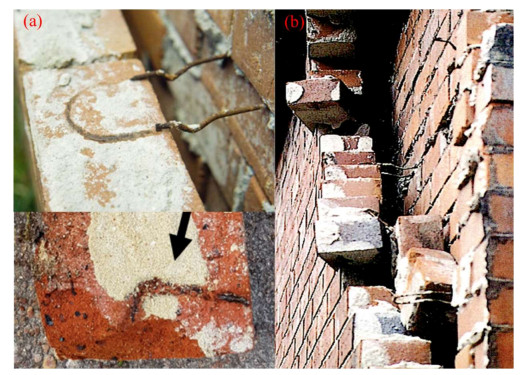
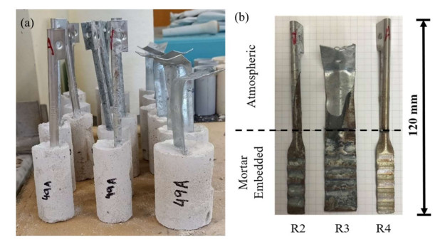
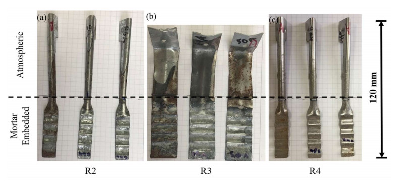
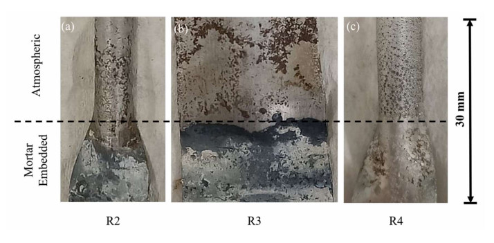
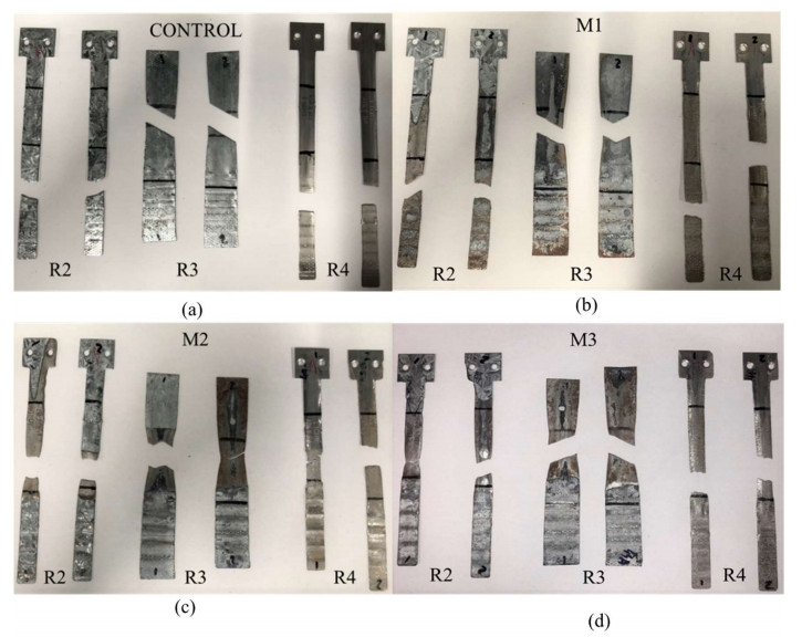
An important structural component for cavity brick and masonry-veneer construction are wall ties. Typically, they are galvanized steel, sufficiently strong to provide continuity for transmission of direct and shear forces. However, field observations show they are prone to long-term corrosion and this can have serious structural implications under extreme events such as earthquakes. Opportunistic observations show corrosion occurs largely to the internal masonry interface zone even though conventional Code requirements specify corrosion testing for the whole tie. To throw light on the issue electrochemical test for 2 grades of galvanized ties and 316 stainless steels combined with three different mortar compositions are reported. Most severe corrosion occurred at the masonry interface and sometimes within the masonry itself. Structural capacity tests showed galvanized ties performed better than stainless steel ties in lieu of stainless steel R4 class ties presenting significantly greater relative losses of yield strength, ultimate tensile strength and elongation structural capacity compared to R2 low galvanized and R3 heavy galvanized tie classes.
Citation: Igor A Chaves, Robert E Melchers, Barbara Jardim do Nascimento, Jordan Philips, Mark Masia. Effects of inter-cavity corrosion on metallic wall ties in masonry structures[J]. AIMS Materials Science, 2022, 9(2): 311-324. doi: 10.3934/matersci.2022019
An important structural component for cavity brick and masonry-veneer construction are wall ties. Typically, they are galvanized steel, sufficiently strong to provide continuity for transmission of direct and shear forces. However, field observations show they are prone to long-term corrosion and this can have serious structural implications under extreme events such as earthquakes. Opportunistic observations show corrosion occurs largely to the internal masonry interface zone even though conventional Code requirements specify corrosion testing for the whole tie. To throw light on the issue electrochemical test for 2 grades of galvanized ties and 316 stainless steels combined with three different mortar compositions are reported. Most severe corrosion occurred at the masonry interface and sometimes within the masonry itself. Structural capacity tests showed galvanized ties performed better than stainless steel ties in lieu of stainless steel R4 class ties presenting significantly greater relative losses of yield strength, ultimate tensile strength and elongation structural capacity compared to R2 low galvanized and R3 heavy galvanized tie classes.

| [1] |
Lawson RM, Popo-Ola SO, Way A, et al. (2009) Durability of light steel framing in residential applications. P I Civil Eng-Munic 163: 109–121. https://doi.org/10.1680/coma.2010.163.2.109 doi: 10.1680/coma.2010.163.2.109

|
| [2] | Jardim do Nascimento B, Chaves IA, Masia MJ, et al. (2017) A field investigation into long-term corrosion of metal wall ties in masonry veneer construction, Proceedings of the 10th Australasian Masonry Conference, Sydney: The University of Newcastle, 1–12. |
| [3] | Brick Industry Association (2003) Wall Ties for Brick Masonry. Reston: Brick Industry Association, 1–15. |
| [4] |
Chaves IA, De Prazer S, Jardim do Nascimento B, et al. (2021) Empirical coastal atmospheric corrosion of masonry metal wall ties. J Corr Mater Degrad 2: 657–665. https://doi.org/10.3390/cmd2040035 doi: 10.3390/cmd2040035
|
| [5] | Page AW, Kleeman PW, Stewart MG, et al. (1990) Structural aspects of the Newcastle earthquake. 2nd National Structural Engineering Conference, Adelaide: Institution of Engineers. |
| [6] | Page CL (1985) Barriers to the prediction of service life of metallic materials, In: Masters LW, Problems in service life prediction of building and construction materials, Netherlands: Springer. |
| [7] | Urban Development Institute of Australia–Western Australia, Modern Methods of Housing Construction, 2020. Available from: https://www.udiawa.com.au/wp-content/uploads/2021/01/FINAL-UDIA-Report-Modern-Methods-of-Construction.pdf. |
| [8] | National Recovery and Resilience Agency, Australian Government, Building codes are not enough to protect homes against water damage in severe storms, 2017. Available from: https://knowledge.aidr.org.au/resources/research-building-codes-are-not-enough-to-protect-homes-against-water-damage-in-severe-storms. |
| [9] | Department of Fire & Emergency Services, Government of Western Australia, Storm safety information, 2021. Available from: https://www.dfes.wa.gov.au/safetyinformation/storm. |
| [10] | Ginger J, Henderson D, Edwards M, et al. (2010) Housing damage in windstorms and mitigation for Australia. James Cook University Research Report: 1–18. Available from: https://researchonline.jcu.edu.au/16337/1/Ginger_IGWRDRR_Aust_Final.pdf. |
| [11] | Standards Association of Australian (2018) AS 3700 Masonry Structures, Sydney: Standards Australia. |
| [12] | Standards Association of Australian (1998) AS 3826 Strengthening Existing Buildings for Earthquake, Sydney: Standards Australia. |
| [13] | Jardim do Nascimento B, Chaves IA, Masia MJ, et al. (2019) Corrosion behaviour of mortar embedded wall-ties in natural and artificial environments, Australasian Corrosion Association Annual Conference, Melbourne: Proceedings of the Corrosion & Prevention, 24–17. |
| [14] |
Hagel MD, Liesel SL, Sturgeon GR (2007) Comparison of theoretical and empirically determined service lives for wall ties in brick veneer steel stud wall systems. J Civ Eng 34: 1424–1432. https://doi.org/10.1139/L07-018 doi: 10.1139/L07-018
|
| [15] | ASTM International (2019) Standard guide for conducting and evaluating Galvanic corrosion tests in electrolytes, ASTM G71-81. |
| [16] | ASTM International (2011) Standard practice for preparing, cleaning and evaluating corrosion test specimens, ASTM G1-03. |
| [17] |
Cragnolino G, McDonald DD (1982) Intergranular stress corrosion cracking of austenitic stainless steel at temperatures below 100 C–A review. Corrosion NACE 38: 406–424. https://doi.org/10.5006/1.3577354 doi: 10.5006/1.3577354
|
| [18] | Melchers RE, Chaves IA (2018) Service life estimation of concrete infrastructures. In: Fernando Pacheco-Torgal, Robert Melchers, Nele de Belie, Eco-efficient Repair and Rehabilitation of Concrete Infrastructures, England: Woodhead, 13–37. |
| [19] | Raupach M (2007) Corrosion of Reinforcement in Concrete: Mechanisms, Monitoring, Inhibitors and Rehabilitation Techniques, England: Woodhead. |
| [20] |
Lidija MS, Valek-Žuljb V, Bjegovića D (2013) Long-term corrosion behaviour of stainless reinforcing steel in mortar exposed to chloride environment. J Corr Sci 69: 149–157. https://doi.org/10.1016/j.corsci.2012.11.035 doi: 10.1016/j.corsci.2012.11.035
|
| [21] | Evans UR (1948) Metallic Corrosion Passivity and Protection, London: Edward Arnold. |
Figures(6) / Tables(5)

Igor A Chaves, Robert E Melchers, Barbara Jardim do Nascimento, Jordan Philips, Mark Masia. Effects of inter-cavity corrosion on metallic wall ties in masonry structures[J]. AIMS Materials Science, 2022, 9(2): 311-324. doi: 10.3934/matersci.2022019


 DownLoad: