Citation: Gérrard Eddy Jai Poinern, Nurshahidah Ali, Xuan Le, Derek Fawcett. Nano-hardness and elastic modulus of anodic aluminium oxide based Poly (2-hydroxyethylmethacrylate) composite membranes[J]. AIMS Materials Science, 2014, 1(3): 159-173. doi: 10.3934/matersci.2014.3.159
| [1] | Mateo Duarte, Andrés Benítez, Katiuska Gómez, Benjamín Zuluaga D, Juan Meza, Yamile Cardona-Maya, Juan S. Rudas, César Isaza . Nanomechanical characterization of a metal matrix composite reinforced with carbon nanotubes. AIMS Materials Science, 2020, 7(1): 33-45. doi: 10.3934/matersci.2020.1.33 |
| [2] | Chaitra Srikanth, Gattumane Motappa Madhu, Hemanth Bhamidipati, Siddarth Srinivas . The effect of CdO–ZnO nanoparticles addition on structural, electrical and mechanical properties of PVA films. AIMS Materials Science, 2019, 6(6): 1107-1123. doi: 10.3934/matersci.2019.6.1107 |
| [3] | Wisawat Keaswejjareansuk, Xiang Wang, Richard D. Sisson, Jianyu Liang . Electrospinning process control for fiber-structured poly(Bisphenol A-co-Epichlorohydrin) membrane. AIMS Materials Science, 2020, 7(2): 130-143. doi: 10.3934/matersci.2020.2.130 |
| [4] | Nikolay A. Voronin . Analysis of the mechanisms of deformation of topocomposites by modeling of the indentation load-displacement curves. AIMS Materials Science, 2019, 6(3): 397-405. doi: 10.3934/matersci.2019.3.397 |
| [5] | Jie Sun, Tzvetanka Boiadjieva-Scherzer, Hermann Kronberger, Kevin Staats, Johannes Holinka, Reinhard Windhager . Surface modification of Ti6Al4V alloy for implants by anodization and electrodeposition. AIMS Materials Science, 2019, 6(5): 713-729. doi: 10.3934/matersci.2019.5.713 |
| [6] | Carlos A. Sánchez, Yamile Cardona-Maya, Andrés D. Morales, Juan S. Rudas, Cesar A. Isaza . Development and evaluation of polyvinyl alcohol films reinforced with carbon nanotubes and alumina for manufacturing hybrid metal matrix composites by the sandwich technique. AIMS Materials Science, 2021, 8(2): 149-165. doi: 10.3934/matersci.2021011 |
| [7] | Sironmani Palraj, Muthaiah Selvaraj, Sundarajan Muthukrishnan . Effect of pretreatments on electrodeposited epoxy coatings for electronic industries. AIMS Materials Science, 2016, 3(1): 214-230. doi: 10.3934/matersci.2016.1.214 |
| [8] | Alain Mauger, Haiming Xie, Christian M. Julien . Composite anodes for lithium-ion batteries: status and trends. AIMS Materials Science, 2016, 3(3): 1054-1106. doi: 10.3934/matersci.2016.3.1054 |
| [9] | Dorel Feldman . Poly(vinyl alcohol) nanocomposites: Recent contributions to engineering and medicine. AIMS Materials Science, 2021, 8(1): 119-129. doi: 10.3934/matersci.2021008 |
| [10] | Cahya Sutowo, Galih Senopati, Andika W Pramono, Sugeng Supriadi, Bambang Suharno . Microstructures, mechanical properties, and corrosion behavior of novel multi-component Ti-6Mo-6Nb-xSn-xMn alloys for biomedical applications. AIMS Materials Science, 2020, 7(2): 192-202. doi: 10.3934/matersci.2020.2.192 |
The nanometre scale porous structure formed during the anodization of aluminium metal in certain acidic media is chemically stable, electrically insulating, optically semi-transparent, bio-inert and biocompatible material. Formation of this porous oxide layer is controlled by macroscopic parameters such as voltage, acid type, acid concentration and temperature [1, 2]. Using a two-step anodization process developed by Masuda et al. it is possible to produce regular, self-organized and highly ordered nanometre scale features that enables these porous membranes to be used as templates [3, 4]. The two-step technique and the electro-chemical parameters used during the fabrication of anodic aluminium oxide(AAO)membranes makes it possible to control a number of surface features such as pore size, pore density and inter-pore distances. In the case of pore size, pore diameter can be adjusted over a wide size range starting from 5 nm up to a maximum of 10 µm [5, 6]. Many researchers have used AAO membrane templates for the manufacture of a one-dimensional(1-D)nanometre scale structure such as nano-wires, nano-rods and nano-tubes within the pore channels [7, 8, 9, 10]. Once the 1-D nanostructures are formed within the pore channel, the AAO template is dissolved using an acid such as H3PO4 or a base such as NaOH. After AAO membrane dissolution, the nano-structures are liberated from the template [11, 12, 13]. Wang et al. recently demonstrated an alternative template-based technique that used highly ordered nano-structured PLGA scaffolds for potential tissue engineering applications [14]. Despite the advantages offered by AAO membranes in terms of template manufacturing and potential tissue engineering applications, it tends to be brittle and fragile. This study, for the first time integrates poly(2-hydroyethylmethacrylate)(pHEMA)into the nano-porous structure of AAO membranes to create a novel biocompatible composite material that improves the mechanical properties of the unprocessed AAO membranes.
From a tissue-engineering point of view, any material under consideration for potential tissue engineering applications must be highly biocompatible. PHEMA is a hydrophilic hydrogel that has a three dimensional cross-linked polymeric structure that is able to swell in an aqueous environment without dissolving. And because of its biocompatibility and lack of toxicity [15, 16] it has been used in a number of biomedical applications such as contact lens, cardiovascular implants and soft tissue replacements [17, 18]. In terms of soft tissue replacement and repair, several studies have shown the enhanced bioactivity of pHEMA can promote cell adhesion, cell growth and protein adsorption [19, 20, 21, 22, 23]. In addition, a number of studies have shown that pHEMA can be used to control the release of pharmaceuticals [24, 25]. Despite pHEMA’s advantageous properties and capabilities, it lacks the mechanical strength and stability needed to provide a resilient scaffold structure in many tissue-engineered applications. By combining the hard, but brittle AAO membrane with the mechanically compliant pHEMA, the resulting biocompatible composite will have mechanical properties that are superior to its individual components. In this study the composites were formed using a solution template wetting technique. Solution template wetting is an established technique for producing one-dimensional polymeric nano-structures. The technique is straightforward, cost effective and is capable of producing uniform nano-structures such as nano-tube s, nano-rods and nano-fibres [26, 27]. AAO membranes are high energy porous materials with a high surface tension, which makes them susceptible to wetting by almost all low energy liquids such as polymer melts. Therefore, the immersion of an AAO membrane into a polymer/solvent mixture results in the infiltration of the mixture into the nano-channelled oxide structure. Within the nano-channels, capillary action forces the pHEMA solution to spread evenly and wet the inside walls. As the solvent evaporates, a thin layer of pHEMA is deposited onto the wall of the nano-channel. Short infiltration times produce nano-tube formation. However, longer infiltration times result in wall thickening that ultimately leads to convergence and the formation of nano-rods [28, 29]. The parameters that control nano-structure formation and morphology in the nano-channels during infiltration are unclear. However, the formation of nanometre scale structures during infiltration are believed to be dependent on several factors: 1)polymer molecular weight; 2)polymer concentration; 3)solvent and separation; 4)capillary flow; 5)infiltration at the pore wall, and 6)pore size.
In this study, the solution template wetting technique was used to infiltrate AAO membranes with pHEMA to form a novel AAO/polymer composite. In-house AAO membranes and commercially available membranes(supplied by Whatman® Anodisc 25, 0.1 µm)were used as the porous ceramic component of the respective polymer composites [30]. Both membrane types had a mean pore diameter of 100 nm, but had different inter-pore spacing and surface roughness. The structure and surface topography of both membrane types and the degree of pHEMA infiltration was examined using Field Emission Scanning Electron Microscopy(FESEM). The hardness of both membrane types and their respective composites was measured using a nano-indentation technique. Data from the nano-indentation study was used to determine the elastic modulus for each of the samples.
All chemicals were purchased from Sigma-Aldrich(Castle Hill: NSW, Australia) and used without further purification. Milli-Q® water(18.3 MΩ cm-1)was used in all aqueous solution preparations and was produced from a Barnstead Ultrapure Water System D11931(Thermo Scientific, Dubuque, IA). The 99.99% pure aluminium foil(0.25 mm thick)used to synthesize the in-house AAO membranes were supplied by Alfa Aesar(USA). The Anodisc membranes(diameter 25 mm, pore size 0.1 µm)used for comparative purposes were supplied by Whatman® Anopore(UK).
Fabrication of the in-house membranes begins with a 100 mm square Aluminium(Al)sheet being cut into 50 mm x 20 mm strips. The strips were placed into a tube furnace and annealed in a nitrogen atmosphere at 500 °C for 5 hours to initiate re-crystallisation and release any mechanical stresses in the strips. After annealing, the strips were washed in acetone, dried and then etched in a 3.0 M sodium hydroxide solution for 5 minutes. The strips were then thoroughly washed in Milli-Q® water and then dried before a thin layer of polymer was applied to one side of the strip. Once the polymer coating had set, the strip was ready for the first step of the two-step anodization procedure. During the first step, each strip was anodized in an electrolyte solution consisting of 0.3 M oxalic acid for 5 hours at 60 V. The oxide layer formed on the non-polymer coated side of the strip at the end of the first step was removed from the substrate by immersion in a stirred acidic solution composed of phosphoric and chromic acid(70 mL/L and 20 g/L, respectively)at 60 °C for 1 hour. This is an important stage in the process, since it removes the oxide layer and exposes a highly r and omised and indented Al substrate surface. The indentations in the substrate surface form the initiation sites for pores formed during the second anodization step [1, 31]. The second anodization step was performed under the same experimental conditions as in the first step, except that the anodization period is only 3 hours long. During the second step, a regular, array of nanometre-sized pores are formed acros s the whole surface of the oxide layer. At the end of the second anodization step, the pores were widened by chemical etching the strip in a 5% solution of phosphoric acid at 35 °C for 15 minutes. Then a thin layer of Acrifix 192 was applied to the anodized side of the strip. The protective layer serves as a physical support for the membrane during the removal of the Al substrate. The substrate was removed by immersing the strip into an acidic solution composed of 0.1 M copper chloride and 7% hydrochloric acid. Following the removal of the Al substrate, the membrane was immersed a 0.3 M solution of phosphoric acid to remove the barrier layer. The acid etching results in the dissolution of the barrier layer and the acrylic support, and leaves an off white coloured oxide membrane. The final stage in producing an AAO membrane is sterilization. During this stage the membrane is immersed in a 30% solution of hydrogen peroxide at 60 ºC for 15 minutes. This was followed by dipping the membrane into a solution of Milli-Q® water for 10 seconds to remove any residual hydrogen peroxide and exposing the membrane to ultraviolet light for 2 h. The membrane was then placed into airtight containers, wrapped in Al foil and stored for future use. Figure 1(a)presents a FESEM micrograph of a typical AAO membrane fabricated in-house using the two-step anodization procedure.
Poly(2-hydroxyethylmethacrylate)(pHEMA)was commercially obtained from Sigma®(USA). The pHEMA/in-house AAO membrane and the pHEMA/ Whatman® Anodisc membrane composites were prepared by using a dip-coater(Dip Coater TLO.01, MTI Corporation, USA). Initially, all membranes were pre-soaked in sodium dodecyl sulphate(SDS)for 1 h. Each membrane was systematically immersed into a solution composed of 1% w/v pHEMA dissolved in a solvent composed of 50% ethanol and 50% MilliQ® water by weight. The membranes were soaked in the polymer/solvent for 1 h before being removed vertically from the solution at a speed of 50 mm/min. Following this procedure, the samples were placed into a vacuum oven(Napco® 5831 E series, USA), which was then pumped down to 85 kPa and set to a temperature of 70 °C. The oven operated in this mode for 2 h, during which time the solvent was completely evaporated. At the end of the 2 h period, the oven heating system was turned off and the membranes cooled down to room temperature. The following day the membranes were removed from the vacuum oven and stored in air tight containers ready for characterisation and analysis.
The in-house AAO membranes and Whatmann® Anodisc membranes were examined using field emission scanning electron microscopy(FESEM)technique. The FESEM micrographs were taken using a Zeiss Neon 40EsB FIBSEM(Carl Zeiss, Oberkochen, Germany)located at the Centre for Materials Research(CMR)at Curtin University of Technology. The field emission electron gun provided both high brightness and high resolution(0.8 nm). Micrographs were taken at various magnifications ranging from 2 to 5 kV using the SE2 and InLens detectors. Samples were mounted on individual substrate holders using carbon adhesive tape before being sputter coated with a 2 nm layer of platinum to prevent charge build up using a Cressington 208HR High Resolution Sputter coater.
Nano-indentation is similar to conventional indentation techniques used to measure hardness. The hardness is determined from the residual indented area left after pressing a very hard tip(i.e. diamond)into the surface of a sample. During the procedure the area of the indentation is measured and the maximum load applied recorded [32, 33]. The hardness(H)is defined by the maximum load(Pmax)divided by the indentation area(Ar) and is expressed by equation(1).
| H=Pmax/Ar | (1) |
Nano-indentation measurements were carried using an Ultra-Micro Indentation System 2000(CSIRO, Sydney, Australia)equipped with a spherical indenter probe(5 µm radius). The testing procedure consisted of each membrane receiving 15 indentations r and omly placed over the surface. The distribution of indentations insured that a mean value of hardness for each membrane could be achieved. In each case a peak probe load of 2 mN was applied to produce the test indentation. The probe was pressed into the membrane surface under the instruments load-control function. During the loading-unloading cycle, the load and displacement data was continuously monitored and recorded. The data values were then used to generate a load-displacement curve. The instruments software was then used to calculate the hardness and elastic modulus from the point of maximum load that occurred in the load-displacement curve.
The frequency and size of surface features such as pore diameter, pore density and inter-pore distance were determined by counting and physically measuring the size of the features found within 10 r and omly selected 1 µm square grids. The grid pattern was overlaid on FESEM micrographs taken of respective membrane and polymer composite surfaces. From this analysis the mean ± st and ard deviation of each surface feature was calculated. A similar technique was used to determine the thickness of the membranes, pore channel uniformity, polymer surface layer thickness, nano-rod geometry and nano-rod infiltration into the pore channels. Cross-section measurements consisted of 10 r and omly selected locations being analysed on FESEM images taken of membrane and composite cross-sections.
The results of the FESEM study of the two membrane types have revealed two different surface terrains. The in-house AAO membranes were found to have a surface architecture that was ordered with an array of uniformly sized pores. Pore ordering could clearly be seen across the undulating l and scape as seen in Figure 1(a). The study revealed a pore density of 53 ± 3 pores/µm2(mean ± std), with a pore diameter of 104 ± 12 nm and an inter-pore distance of 150 ± 14 nm. The second membrane type used in this study for comparative purposes was the commercially available Whatman® Anopore(Anodisc)membrane. The Anodisc membrane is composed of a high purity porous alumina matrix. The pores present in this matrix are circular in shape with a mean pore diameter of 120 ± 45 nm. While the estimated inter-pore distance of around 0.32 µm was determined from pore density measurements. Analysis of the FESEM micrographs revealed that the in-house membranes had a fairly consistent thickness of around 40 µm, while the Anodisc membranes were typically around 60 µm in thickness. Furthermore, the pore wall thickness in the Anodisc membranes was not consistent across the surface, with numerous rough edges protruding up from the surface as seen in Figure 1(b). Overall, the l and scape of the Anodisc membranes was found to be very rough compared to those of the in-house membrane, which tended to have smooth, undulating nanometre scale topography.
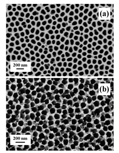 Figure 1. FESEM micrographs of(a)in-house electrochemically synthesized AAO membrane and (b)Whatman® Anopore(Anodisc)membrane.
The solution template wetting technique was used to infiltrate both membrane types. After 1 h of immersion in the pHEMA-solvent, it was found that pHEMA not only wetted the surface of the membranes but also infiltrated into the nano-porous structure of both membrane types. Figure 2(a)presents a FESEM micrograph of an Anodisc membrane after 1 h of immersion in the pHEMA-solvent solution. For comparative purposes the left h and side of the Anodisc membrane was not immersed. Between the dipped and non-dipped portions of the membrane is a region of partial infiltration. In this region there are a number of pores which are either partially filled or not filled as indicated by the red arrows in Figure 2(a). The enlarged micrograph presented in Figure 2(b)highlights a number of pores not filled in the partial infiltration region. Inspection of Figure 2(b)reveals that the vast majority of pores are filled with pHEMA, but many of the rough wall edges are still visible. FESEM analysis of membrane cross-sections revealed that the thickness of the pHEMA surface coating ranged from around 50 nm up to 300 nm and was found to be dependent on the underlining surface topography.
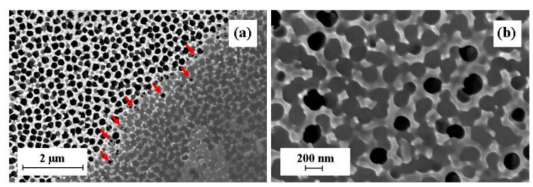 Figure 2. Immersion of a Whatman® Anodisc membrane for 1 h:(a)Partial immersion of membrane resulting in complete infiltration of pHEMA in the immersion zone;(b)a typical enlarged view of the partial infiltration region showing a number of pores not filled.
The results obtained from solution wetting of in-house AAO membrane were similar to those of the Anodisc membranes. The structure morphology formed within the pore channels of both membrane types was predominantly rod like. Figure 3(a)presents an FESEM micrograph showing a typical l and scape view of an in-house AAO membrane after pHEMA infiltration. An interesting feature seen in the infiltrated in-house membranes is the presence of a small number of partially filled pores. The enlarged micrographs presented in Figures 3(b) and (c)reveal the structure within the partially filled pores. Both micrographs reveal the formation of nanometre-sized tubes. Red arrows in both micrographs indicate the partially filled pore channels. The presence of the partially filled membrane suggests that during the immersion period polymer layers were slowly deposited on the channel walls. The presence of a small number of partially filled channels suggests that a longer infiltration time would result in complete convergence of the pHEMA layers and form a pHEMA nano-rod. Studies by Schlitt et al. revealed that the polymer molecular weight, concentration and solvent type can have a significant influence on the morphology of nanometre structures formed within pore channels [34]. The results of their study also suggested that nanometre scale polymer rods could be formed with molecular weights below 7, 000 g/mol. Molecular weights between 17, 000 and 75, 000 g/mol predominantly produced nanometre scale tubes and above 75, 000 g/mol only nanometre scale tubes could be formed [34].
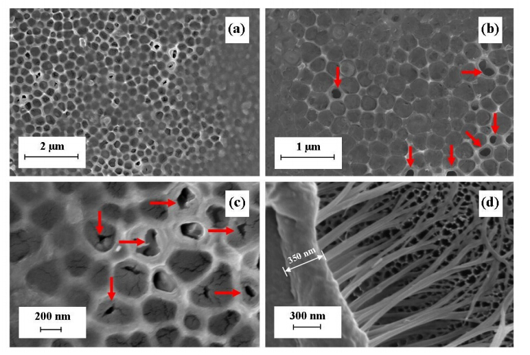 Figure 3. In-house synthesised AAO membrane:(a)Overview of a AAO membrane infiltrated by pHEMA;(b)enlarged view showing the presence of small numbers of nanometre sized hollow structures being formed;(c)detailed view of incompletely formed nanometre sized rods; and (d)pHEMA surface layer and nano-rods lifted out of membrane channels.
Similar studies by Feng and Jin, also found that nanometre scale polystyrene rods could be formed during a 24 h infiltration period with molecular weights ranging from 5, 200 g/mol to 650, 000 g/mol [35]. Their investigation also found that low concentrations of polystyrene(usually between 20 to 40 mg/mL), could infiltration and fill the template. At higher concentrations(typically around 150 mg/mL), they found elongated tube-like structures being formed. The results of Feng and Jin are in direct contrast to those of Pasquali et al. In Pasquali et al. study, a 1% wt polystyrene solution was used to infiltrate a template over a varying single infiltration period ranging from 30 s to 24 h. Templates were completely filled with polystyrene to form rods for molecular weights ranging from 4, 000 g/mol to 10, 000 g/mol for all infiltration times. Templates were partially filled with polystyrene to form tubes for molecular weights between 18, 100 g/mol and 973, 000 g/mol for infiltration times ranging from 30 s to 12 h. However, after 12 h all templates were completely filled to form nanometre scale rods [28].
The polymer infiltration results of this study using pHEMA tend to follow the results reported by Pasquali et al. [28]. Namely, low concentrations of pHEMA were able to infiltrate and form nanometre scale rods within the pore channels. Figure 3(d)presents an FESEM micrograph of a pHEMA surface coating partially lifted off the underlining in-house membrane. From the micrograph the surface layer was estimated to be 350 nm thick and was firmly attached to the underlining rods that had formed in the pore channels. Analysis of micrographs taken of various membrane cross-sections revealed that the diameter of the nano-rods ranged from 60 to 90 nm and the rod generally filled the full length of the pore channel(40 µm). The difference in experimental results reported by Feng and Jin [35] and Pasquali et al. [28] may be due in part to the different experimental procedure and infiltration techniques used. The present study has revealed that a pHEMA/solvent solution was capable of infiltrating a nanometre scale pore channel structure. Then deposit and accumulate pHEMA on the channel walls. Pre-soaking the membranes in a solution of SDS surfactant for 1 h prior to infiltration was found to promote infiltration of the pHEMA-solvent solution in the subsequent dipping procedure. After the 1 h infiltration period, the vast majority of pore channels were filled forming solid rod-like structures. The number of partially formed rods in the pore channels was less than 3% of the total number of pores. The presence of a small number of partially formed rods or nano-tubes in both the in-house and the Anodisc membranes suggest that the infiltration technique used could be the principal factor in influencing the formation of a nano-rod or nano-tube. However, further work is needed to completely inve stigate the effects of the present solution template wetting technique. For example, examining the influence of molecular weight and pHEMA concentrations used during the dipping procedure. In addition, further work is needed to investigate the biocompatibility of the composite membranes, the influence of surface topography and the influence of partially filled pores on various cell lines.
In the second stage of this study involved determining the elastic and hardness properties of the various membranes and composites. The nano-indentation technique was used to measure the hardness of the membranes and composites [32]. Figure 4 presents the graphical results of the hardness testing procedure, with Figure 4(a)presenting the respective membrane responses to the various loading and unloading cycles of the nano-indention process [33, 36]. The data produced during the testing procedure was used to determine the hardness values for the respective membranes and composites. The maximum indentation depth produced by the nano-indenter in the respective membranes and composites ranged from 0.131 µm to a maximum of 0.163 µm under a maximum indenter load of 2 mN.
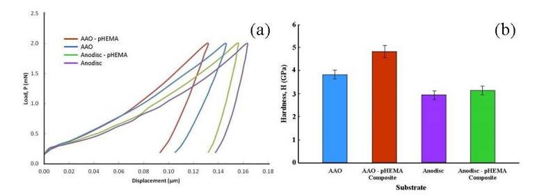 Figure 4. (a)Load displacement(P-h)curve of test membranes;(b)Calculated hardness values of test membranes.
The results of hardness testing revealed that the in-house AAO membrane had a hardness value of 3.81 ± 0.2 GPa, while the commercially available AAO membrane(Anodisc)was 0.88 GPa lower, with a hardness value of 2.93 ± 0.2 GPa. The incorporation of pHEMA into the nano-porous structure of both membrane types resulted in an improvement in the hardness value for both types as seen in Figure 4(b). The in-house AAO membrane based composite was found to have a hardness value of 4.88 ± 0.3 GPa, which equates to an improvement in the hardness value of 28% compared to the non-polymer composite membrane. However, in the case of the Anodisc/pHEMA composite the hardness value increased marginally from 2.93 ± 0.19 GPa up to 3.03 ± 0.19 GPa, an increase of only 3.4%.
A similar trend was also seen in the calculated elastic modules derived from the respective load displacement curves for each membrane. The elastic modulus of the in-house AAO and Anodisc membranes was calculated to be 79.89 ± 3.8 GPa and 123.75 ± 7.2 GPa respectively, and is presented graphically in Figure 5. Both values are reflective of the mechanical nature of the membranes. For example, the in-house AAO membrane tends to be brittle and fractures easily. The test results indicate incorporation of pHEMA into the nano-porous structure improves the elasticity of both membrane types. The elastic modulus of the in-house AAO/pHEMA composite was significantly greater, with a calculated value of 95.15 ± 3.0 GPa compared to non-polymer membrane whose value was only 79.89 ± 3.8 GPa. This result equates to an improved in membrane elasticity of 19.1%. On the other h and , the calculated elastic modulus for the Anodisc membrane was found to be 123.75 ± 7.2 GPa, while the AAO/pHEMA was only 125.62 ± 6.8 GPa. The small increase in elasticity for the Anodisc/pHEMA composite reflected an improvement of only 1.5%.
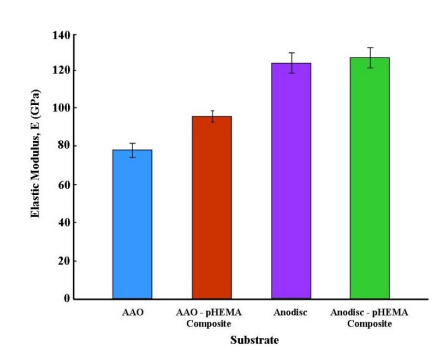 Figure 5. The calculated elastic modulus for test membranes.
The improvement in hardness of 3.4% and the enhancement of 1.5% in the elastic modulus of the Anodisc/pHEMA membrane reflected only a marginal improvement in the mechanical properties. Furthermore, if we take into account the st and ard deviation of the measurements, the improvement in the hardness and elastic modulus is negligible. However, this was not the case for the in-house AAO/pHEMA composite. In this case there was a significant improvement in hardness of around 28%, while the enhancement in the elastic modulus was found to be 19%. A major factor that contributed to the enhanced hardness and elastic modulus of the in-house AAO/pHEMA composite was the well developed, smooth and consistent pore channels in the membrane. This architecture provided large active surfaces which were capable of promoting strong interfacial adhesion between the nano-porous structure of the membrane and the infiltrated pHEMA matrix. In the case of the Anodisc/pHEMA composite, the pore channels were less consistent and provided fewer active surfaces capable of providing adequate adhesion sites. In addition, the very rough surface of the Anodisc membrane prevents the formation of a smooth intact pHEMA surface layer. This rough terrain can be seen in Figure 2(b), which clearly shows the irregular pore wall structure protruding through the thin pHEMA surface covering. Overall, the hardness and elastic modulus of the in-house AAO membrane has been significantly improved by the incorporation of pHEMA into the nano-porous structure. In the case of the AAO/pHEMA composite, incorporation of pHEMA made the membrane less brittle and more resilient during h and ling.
The present study has successfully demonstrated that an in-house nano-porous AAO membrane and a commercially available AAO membrane can be successfully infiltrated by Poly(2-hydroxyethylmethacrylate)to form a unique AAO/polymer composite. Characterization studies have revealed that the polymer infiltrates the nanometre scale porous structure to form a composite membrane with improved hardness and elasticity. The most significant improvement in both hardness and elasticity was seen in the in-house AAO membranes, with improvements in hardness and elasticity of around 28% and 19% respectively. Significant improvements in hardness and elastic modulus seen in the in-house AAO membranes make it more robust by reducing the effects of its brittle nature. However, further studies are needed to quantify the effects of varying the membrane pore size, membrane surface topography and surface chemistry. In addition, further work is needed to elucidate the biological compatibility, the influence of surface chemistry and surface topography on various cell lines.
Ms Nurshahidah Ali and Ms Xuan Le would also like to acknowledge Murdoch University for providing PhD Scholarships to undertake the aluminium oxide and polymer studies as part of their respective PhD projects.
The authors report no conflict of interest in this work.
| [1] |
Poinern GEJ, Ali N, Fawcett D (2011) Progress in nano-engineered anodic aluminium oxide membrane development. Mater 4: 487-526. doi: 10.3390/ma4030487

|
| [2] |
Shingubara S (2003) Fabrication of nanomaterials using porous alumina templates. J Nanoparticle Res 5: 17-30. doi: 10.1023/A:1024479827507
|
| [3] |
Masuda H, Yada K, Osaka A (1998) Self-ordering of cell configuration of anodic porous alumina with large-size pores in phosphoric acid solution. Jpn J Appl Phys 37: L1340-L1342. doi: 10.1143/JJAP.37.L1340
|
| [4] |
Chik H, Xu JM (2004) Nanometric superlattices: non-lithographic fabrication, materials and prospects. Mat Sci Eng R 43: 103-138. doi: 10.1016/j.mser.2003.12.001
|
| [5] | Thompson GE, (1994) Surface characteristics of aluminium and aluminium alloys, TALAT 5101, European Al Ass. |
| [6] | Gultepe E, Nagesha D, Sridhar S, et al. (2010) Nanoporous inorganic membranes or coatings for sustained drug delivery in implantable devices. Adv. Drug Deliver Rev 3(8): 305-315. |
| [7] | Prasad S, Quijano J (2006) Development of nanostructured biomedical micro-drug testing device based on in situ cellular activity monitoring. Bioelectron 21(7): 1219-1229. |
| [8] | Eftekhai A, (2008) Nanostructured materials in electrochemistry, Wiley-VCH: 24-25. |
| [9] |
Liu L, Lee W, Huang Z, et al. (2008) Fabrication and characterization of a flow-through nano-porous gold nanowire/AAO composite membrane. Nanotechnology 19: 335604-335609. doi: 10.1088/0957-4484/19/33/335604
|
| [10] |
Wang HJ, Zou CW, Yang B, et al. (2009) Electro-deposition of tubular-rod structure gold nano wires using nanoporous anodic oxide as template. Electrochem Commun 11: 2019-2022. doi: 10.1016/j.elecom.2009.08.042
|
| [11] | Song GJ, Li JJ, She XL (2006) Research progresses of polymer nanotubes. Polym Bull 6(74):31-37. |
| [12] | Al-Kaysi RO, Ghaddar TH, Guirado G (2009) Fabrication of one-dimensional organic nanostructures using anodic aluminium oxide templates. J Nanomaterials 2009: 1-14. |
| [13] | Oh HJ, Jeong Y, Kwon SH, et al. (2007) Fabrication of polymer nanotubes using alumina template. Solid State Phenomena 124-126(2): 1109-1112. |
| [14] |
Wang GJ, Lin YC, Li CW, et al. (2009) Fabrication of orderly nanostructured PLGA scaffolds using anodic aluminium oxide templates. Biomed Microdevices 11: 843-850. doi: 10.1007/s10544-009-9301-0
|
| [15] | Peppas NA, (1987) Hydrogels in medical and pharmacy, Boca Raton, USA: CRS Press, Vol. I-III. |
| [16] | Perova TS, Vij JK, Xu H (2007) Fourier transform infrared study of poly (2-hydroxyethylmethacrylate) pHEMA. Colloid Polym Sci 275(4): 323-332. |
| [17] |
Pal K, Banthia AK, Majumdar K (2009) Polymeric hydrogels: Characterization and Biomedical Applications-A mini review. Des Monomers Polym 12: 197-220. doi: 10.1163/156855509X436030
|
| [18] | Gibas I, Janik H (2003) Review: Synthetic polymer hydrogels for biomedical applications. Chem Tech 4(4): 297-304. |
| [19] | Harkes G, Feijen J, Dankert J (1991) Adhesion of Escherichia coli on to a series of poly (methacrylates) differing in charge and hydrophobicity. Biomaterials 12(9): 853-860. |
| [20] |
Guan JJ, Gao GY, Feng LX, et al. (2000) Surface photo-grapting of polyurethane with 2-hydroxyethyl acrylate for promotion of human endothelial cell adhesion and growth. J Biomater Sci Poly Ed 11: 523-536. doi: 10.1163/156856200743841
|
| [21] |
Lopez GP, Ratner BD, Rapoza RJ, et al. (1993) Plasma deposition of ultrathin films of poly (2-hydroxyethylmethacrylate) surface analysis and protein adsorption measurements. Macromolecules 26: 3247-3253. doi: 10.1021/ma00065a001
|
| [22] |
Morra M, Cassinelli CJ (1995) Surface field of forces and protein adsorption behaviour of poly (2-hyroxyethylmethacrylate) films deposited from plasma. J Biomed. Mater. Res 29: 39-45. doi: 10.1002/jbm.820290107
|
| [23] |
Peluso G, Petillo O, Anderson JM, et al. (1997) Melone MAB, Eschbach FO and Huangs SJ, The differential effects of poly (2-hydroxyethylmethacrylate) and poly (2-hydroxyethylmethacrylate)/poly (caprolactone) polymers on cell proliferation and collagen synthesis by human lung fibroblasts. J Biomed. Mater. Res 34: 327-336. doi: 10.1002/(SICI)1097-4636(19970305)34:3<327::AID-JBM7>3.0.CO;2-M
|
| [24] | Hsiue GH, Guu JA, Cheng CC (2001) Poly (2-hydroxyethyl methacrylate) film as a drug delivery system for pilocarpine. Biomaterials 22(13): 1763-1769. |
| [25] | Ferreira L, Vidal MM, Gil MH (2000) Evaluation of poly (2-hydroxyethylmethacrylate) gels as drug delivery systems at different pH values. Int J Pharm 194(2): 169-180. |
| [26] | Cepak VM, Martin CR (1999) Preparation of polymeric micro and nanostructures using a template based deposition method. Chem Mater 11(5): 1363-1367. |
| [27] | Song GJ, She XL, Fu Z et al. (2004) Preparation of good mechanical property polystyrene nanotubes with array structures in anodic aluminium oxide using a simple physical techniques. J. Mater. Res 19(11): 3324-3328. |
| [28] | Pasquali M, Liang J, Shivkumar S (2011) Role of AAO template filling process parameters in controlling the structure of one dimensional polymer nanoparticles. Nanotechno 22: 1-10. |
| [29] | Zhang M, Dobriyal P, Chen JT et al. (2006) Wetting transitions in cylindrical aluminium nano-pores with polymer melts. Nano Lett 6(5): 1075-1079. |
| [30] | Whatman® Anopore www.whatman.com/products. |
| [31] |
Ghorbani M, Nasirpouri F, Iraji-zad A, et al. (2006) On the growth sequence of highly ordered nano-porous anodic aluminium oxide. Mater Desing 27: 983-988. doi: 10.1016/j.matdes.2005.02.018
|
| [32] | Rajagopalan S, Vaidyanathan R (2002) Nano and micro scale mechanical characterization using instrumented indentation. J Electron Mater 54(9): 45-60. |
| [33] | Oliver WC, Pharr GM (1992) An improved technique for determining hardness and elastic modulus using load and displacement sensing indentation experiments. J Mater Res7(6):1564-1583. |
| [34] |
Schlitt S, Greiner A, Wendorff J (2008) Cylindrical Polymer Nanostructures by Solution Template Wetting. Macromolecules 41: 3228-3234. doi: 10.1021/ma071822k
|
| [35] |
Feng X, Jin Z (2009) Spontaneous Formation of Nanoscale Polymer Spheres, Capsules, or Rods by Evaporation of Polymer Solutions in Cylindrical Alumina Nanopores. Macromolecules 42: 569-572. doi: 10.1021/ma8024283
|
| [36] |
Mammeri F, Le Bourhis E, Rozes L et al. (2005) Mechanical properties of hybrid materials. J Mater Chem 15: 3787-3796. doi: 10.1039/b507309j
|
| 1. | Christian N. Kotanen, Dileep R. Janagam, Rachelle Idziak, Luke Rhym, Ryan Sullivan, Ann M. Wilson, Tao L. Lowe, Anthony Guiseppi-Elie, Partitioning of coomassie brilliant blue into DMAEMA containing poly(HEMA)-based hydrogels, 2015, 72, 00143057, 438, 10.1016/j.eurpolymj.2015.07.035 |


Figures(5)

Gérrard Eddy Jai Poinern, Nurshahidah Ali, Xuan Le, Derek Fawcett. Nano-hardness and elastic modulus of anodic aluminium oxide based Poly (2-hydroxyethylmethacrylate) composite membranes[J]. AIMS Materials Science, 2014, 1(3): 159-173. doi: 10.3934/matersci.2014.3.159


 DownLoad: