
Citation: J. Appelbaum. A static multiple detector solar radiation sensor[J]. AIMS Energy, 2020, 8(5): 802-818. doi: 10.3934/energy.2020.5.802
[1] | Djelloul Benatiallah, Ali Benatiallah, Kada Bouchouicha, Bahous Nasri . Estimation of clear sky global solar radiation in Algeria. AIMS Energy, 2019, 7(6): 710-727. doi: 10.3934/energy.2019.6.710 |
[2] | J. Appelbaum . Shading and masking affect the performance of photovoltaic systems—a review. AIMS Energy, 2019, 7(1): 77-87. doi: 10.3934/energy.2019.1.77 |
[3] | Rami Al-Hajj, Ali Assi . Estimating solar irradiance using genetic programming technique and meteorological records. AIMS Energy, 2017, 5(5): 798-813. doi: 10.3934/energy.2017.5.798 |
[4] | Humaid Abdullah ALHinai, Azrul Mohd Ariffin, Miszaina Osman . Revolutionizing Oman's energy network with an optimal mixture renewable energy source. AIMS Energy, 2023, 11(4): 628-662. doi: 10.3934/energy.2023032 |
[5] | Cristiana Brasil Maia, Gisele Mol da Silva, Luiz Felippe Guardia Bianchi, André Guimarães Ferreira . Performance study of a baffled solar dryer. AIMS Energy, 2021, 9(6): 1136-1146. doi: 10.3934/energy.2021052 |
[6] | Fadhil Khadoum Alhousni, Firas Basim Ismail, Paul C. Okonkwo, Hassan Mohamed, Bright O. Okonkwo, Omar A. Al-Shahri . A review of PV solar energy system operations and applications in Dhofar Oman. AIMS Energy, 2022, 10(4): 858-884. doi: 10.3934/energy.2022039 |
[7] | Gemma Graugés Graell, George Xydis . Solar Thermal in the Nordics. A Belated Boom for All or Not?. AIMS Energy, 2022, 10(1): 69-86. doi: 10.3934/energy.2022005 |
[8] | Ming-Tang Tsai, Chih-Jung Huang . Integration of the radial basis functional network and sliding mode control for the sunshine radiation forecast. AIMS Energy, 2024, 12(1): 31-44. doi: 10.3934/energy.2024002 |
[9] | Hayder S. Al-Madhhachi, Ahmed M. Ajeena, Nihad A. Al-Bughaebi . Dynamic simulation and energy analysis of forced circulation solar thermal system in two various climate cities in Iraq. AIMS Energy, 2021, 9(1): 138-149. doi: 10.3934/energy.2021008 |
[10] | Abdulrahman Almutlaq . Indoor experiments of a horizontal multiple effects diffusion solar still: Influence of heat input and the number of stages. AIMS Energy, 2024, 12(2): 532-547. doi: 10.3934/energy.2024025 |
With the broadening applications of solar energy conversion system, solar radiation data on different tilted and oriented surfaces are needed, as well the angular distribution of the diffuse radiation in the sky. Solar radiation data collected by meteorological stations are usually not sufficient for efficient use of the solar applications. The most common instruments at meteorological stations are pyrheliometers for measuring the direct beam radiation, pyranometers for measuring the combined direct beam and the diffuse radiation on a horizontal surface, and pyronometers with an addition shaded ring for measuring the diffuse radiation on a horizontal surface. Converting the solar radiation data supplied by the meteorological stations to tilted surfaces at different orientations may introduce considerable errors resulting from different modeling of the diffuse radiation (isotropic and anisotropic models). To mitigate these errors, authors proposed multi-sensor radiometers for measuring the direct beam component and the angular distribution of the solar radiation emanating from the sky-dome. Two types of static multi-sensor instruments were proposed. One type is based on conventional pyranometers placed on different inclination and azimuth angles [1,2] and a second type is based on a number of detectors covering a hemispherical-member [3,4,5,6]. The instrument in [3] incorporates 25 radiation sensors placed on a metal hemisphere. The sensor consists of an absorption blackened surface copper plate attached to a two-terminal temperature transducer. The solar radiation sensor in [4] employs 24 solar cell detectors positioned evenly on a hemispherical body member, designed to intercept simultaneously the directional solar radiation. The sensor is attached to a data-logger and processing unit. The sensor in [5] comprises five monocrystalline Si cells mounted tangentially along a hemispherical structure. The idea of a multi-detector solar sensor in [6] is based on [4,5] and includes more than hundreds photodiodes covering the hemispherical surface.
The purpose of the present study is to design a small static sensor for mapping (measuring) the solar radiation emanating from the sky. The sensor includes a plurality of individual directionally solar radiation detectors, oriented radially around a hemispherical surface and individually shielded so as to simultaneously intercept only directional solar radiation, see Figure 1. By processing the measurements, the direct beam, diffuse and global radiation on a horizontal and on any desired tilted and oriented surface may be derived. Moreover, measurements of the directional distribution of solar radiation from sky and from reflected surfaces in the direction of the detectors may be obtained and the anisotropic diffuse radiation models may be verified and modified as necessary. The sensor may also be used for solar tracking systems by orienting to directions of maximum radiation at any time during the day. The solar radiation measurements of the sensor were compared with a conventional pyranometer. Basically, the present sensor is a step further in the design of the conceptual designed sensor in [4]. The objective is to construct a sensor with small dimensions and of light-weight, detectors and hemispherical dome hermetically sealed and the sensor machined close to a prototype product. In addition, the deployment of the detectors on the hemispherical-member of the present sensor is based on the problem of closest packing of N equal non-overlapping circles on a sphere [7] to obtain a better coverage of the sky. The article describes the concept, construction, theory and test results.
The design of the present sensor includes 17 detectors consisting of silicon photodiodes. The disposition of the detectors on the hemispherical surface is based on the problem of closest packing of N equal non-overlapping circles on a sphere [7]. Each detector is characterized by the angles (αi,γi,ηi) where αi is the elevation angle with respect to the base plane of the hemisphere, γi is the detector’s azimuth angler with respect to south (positively in a clockwise direction), and ηi is the view angle (see Figure 2). The detectors are arranged in two circles and one detector on the top, see Figure 2. In circle #1 there are 10 detectors with elevation angle of α1=17.20, and in circle #2 the number of detectors is 6 with elevation angle α2=52.20.
The first detector in circle #1 is positioned at azimuth γ1=00 and the detectors are uniformly distributed with 360 apart. The first detector in circle #2 is positioned at azimuth γ2=60 and the detectors are uniformly distributed with 600 apart. All detectors have equal view angles η. The detectors satisfy the conditions of no overlapping of their coverage regions to assure a uniform coverage of the hemisphere by the detectors.
The design is based on 17 detectors positioned on 50 mm in diameter of the hemispherical-member made of aviation grade aluminum 2024. Silicon photodiodes casing TO18 were used as detectors. Brass was used as sleeves for the detector housing and silicon O-rings for sealing the aluminum parts. RTV 560 space grade adhesive is used for the attachments of the detectors to the housing sleeves. The hemispherical-member consist of two parts, see Figure 1: (1) the hemisphere including a flange, (2) the bottom cover containing a flange and space for connectors and wires, and a hollow stem for attaching the sensor to a post and for the wiring cable. Figure 3 shows the sensor housing, the detectors bores and their threads, and the two flanges for tightening by screws.
Photodiodes are generally produced in hermetically sealed casing of certain dimensions. The view angle of these detectors are usually larger than the view anglers needed for solar radiation distribution measurement angles. To decrease the view angle, the detectors are assembled in hermetically sealed sleeves. Figure 4 shows the dimensions and view angles of the detector-assembly. The casing of the photodiode is marked in dash lines with height Hp and diameter Dp. The dimeter of the active part of the photodiode is denoted by d. The sleeve dimensions are H - height and D -dimeter (window diameter). The sleeve producers two view angles η1 and η2 where for η⩽η1 the solar rays impinges on the full active area of the photodiode, and for rays coming from an angle η1⩽η⩽η2 only part of the rays falls on the detector area. The detector radiation incident angles and the detector response are shown in Figure 5a, b, c, respectively.
The relation between the view angles and the dimensions of the detector assembly are given by (see Figure 4):
tanη1=(D−d)/2H,tanη2=(D+d)/2H, obtaining η1=9.70 and, η2=17.20.
Figure 6 shows the detector assembly. The photodiode and caps were sealed to the detector housing with RTV 560 in an inert atmosphere of dry nitrogen. The sleeves containing the detectors are screwed into the bores of the hemispherical member, see Figure 3.
The detectors and the detector assemblies (detectors in their housing) were tested in the laboratory for response and alignment. These tests were performed in an optical laboratory using a laser beam, lenses, optical table and associated equipment. The angular response of the detector assembly is shown in Figure 7. Temperature compensation calibration were also performed in the laboratory for a wide range of temperatures T (T25 is the reference temperature) and for different solar irradiance levels G to obtain the temperature compensation coefficients ΔG/ΔT of the detector’s response. A reading G of a detector is corrected to G∗ by:
G∗=G[1−ΔGΔT(T−T25)]. | (1) |
Table 1 lists the irradiance and temperature ranges and the corresponding temperature compensation coefficients.
Coefficient ΔG/ΔT (% / ℃) | Irradiance (W/m2) | Temperature range (℃) |
−0.15 | 0÷500 | (−)25÷(+)25 |
−0.40 | 0÷500 | (+)25÷(+)100 |
−0.08 | 500÷1000 | (−)25÷(+)25 |
−0.17 | 500÷1000 | (+)25÷(+)100 |
The sensor operates in conjunction with an electronic unit for logging, processing and storing data. The unit serves as an interface between a host computer and the sensor, it scans periodically the detectors and transmits the measured values to the host computer using a dedicated protocol. The electronic unit consists of amplifiers, analog to digital conversion, a micro-controller, reference voltages and a thermocouple for temperature compensation. The digital transmitting of the detectors’ signals is performed using two multiplexers and A/D converter with 8bit resolution. The A/D converter is embedded in the controller. The conversion time for each channel is a function of the crystal frequency of the controller and is 32μsec. The microcontroller has 128 Byte RAM, 2 K code of flash memory type, A/D converter with 8bit resolution and serial interface communication. A thermocouple of type T is used to measure the temperature of the detectors. The hot junction of the thermocouple is embedded inside the hemispherical-member which is made of aluminum (high conductivity) which represents well the detectors’ temperature. The cold junction measures the ambient temperature. The thermocouple voltage is amplified and transmitted to the scanning unit for conversion to digital form.
The global irradiance on a plane is the sum of the direct beam and diffuse components. The irradiance is calculated from the readings of the detectors and the calculation is based on the angles between the detectors and the plane. The solar angles involved in the direct beam radiation is given in [8]. The location of the detectors on the hemispherical-member is denoted by the pair (αi,γi), where αi is the elevation of detector i with respect to a base plane and γi is the azimuth of detector i : south-zero, east-negative and west-positive. The angle θi between the normal to the detector i and the solar ray is given by:
cosθi=cosαscosαicos(γs−γi) | (2) |
where αs is the solar elevation angle and γs is the solar azimuth angle, south-zero, east-negative and west-positive.
As mentioned, each detector is characterized by two angles η1 and η2 determined by the detector and the sleeve dimensions (see Figure 4).
Two regions of operation are identified:
(a) The sun rays intercept directly a single detector i, i.e., θi⩽η2.
(b) No detector intercepts directly the sun rays, i.e., θi>η2.
Denoting by Gi the direct beam reading of detector i and by Gj the direct beam reading of detector j closest to detector i, at measured time t where minθj>η2. Two cases are identified:
(a) reading of detector i and reading of detector j are not close to each other, Gi/GiGj>aGj>a, the direct beam irradiance Gbi on detector i is given by:
Gbi=Gicosθifor0<θi<η1 | (3) |
and
Gbi=Gicosθi⋅(η1−η2)(θi−η2)forη1<θi<η2−ε | (4) |
where a is an empirical value (a>1.5), and ε is an empirical value (ε=0.50) that avoids obtaining irrational results for θi≈η2.
(b) reading of detector i and reading of detector j are close to each other Gi/GiGj⩽bGj⩽b :
Gbi=12(Gi+Gj)cosθifor0<θi<η1 | (5) |
Gbi=12(Gi+Gj)cosθi⋅(η1−η2)(θi−η2)forη1<θi<η2−ε | (6) |
where b is an empirical value b⩽1.1.
For case-(a) reading of detector i and reading of detector j are not close to each other, Gi/GiGj>aGj>a, the diffuse radiation is determined by:
ˉGdi(t)=[Gdj+¯Gdi(t−1)]/2 | (7) |
where
¯Gdi(t) is the diffuse component of intercepted detector (i) at measurement time t.
¯Gdi(t−1) is the diffuse component of intercepted detector (i) at measurement time t−1.
Gdj is the diffuse component of detector j closest to detector i measurement time t, for minθj>η2.
For case-(b) reading of detector i and reading of detector j are close to each other Gi/GiGj⩽bGj⩽b.
ˉGdi(t)=[Gdk+ˉGdi(t−1)]/2 | (8) |
where Gdk is the diffuse component of detector k second closest to detector i at measurement time t, for minθk>(θi,θj).
All other detectors do not intercept the sun therefore they measure diffuse irradiance only.
We assume that the sky consists of radiation sources whose number corresponds to the number of detectors of the sensor, and the directions of these sources coincide with the direction of the detectors. We also assume that a detector sees the sky uniformly with a view angle η2 instead of the two angles η1 and η2, corresponding to the actual reading Gdi of the diffused irradiance. This assumption may increase the accuracy of the irradiance calculation on a plane, see Appendix A. The diffuse irradiance is given by:
˜Gdi=Gdi(η2−η1)(cosη1−cosη2)sinη2 | (9) |
The angle between the normal to an inclined plane β facing south with an angle γc and the normal to detector i is given by [8], see Figure 8:
cosφi=cosαicos(γi−γc)sinβ+cosβsinαi | (10) |
The contribution of the diffuse irradiance reading of detector i on the inclined plane is therefore given by: ˜Gdicosφi. It is assumed that the direct beam component of the solar irradiance when no detector intercept the sun (θi>η2−ε) is given by the reading of a detector closets to the sun, i.e., for minθi. The contribution of the direct beam irradiance of that detector on the inclined plane is given by Gbcosθs, see Figure 8, where:
cosθs=cosαscos(γs−γc)sinβ+cosβsinαs | (11) |
where θs is the angle between the normal to the plane and the sun.
The global irradiance on an inclined plane β oriented by an angle γc with respect to south is given by the sum of the direct beam and diffuse components, respectively:
G(β,γc)=Gbcosθs+[∑cosφi>0˜Gdicosφi]/PSC | (12) |
where the summation is only from those detectors satisfying cosφi>0. The diffuse irradiance is divided by the percent of sky coverage PSC [7] since the detector’s readings do not contain information that are not covered by the detectors.
The trajectory band of the sun movement for the whole year is shown in Figure 9 by the dark color. The lower trajectory is for December 21 and the upper trajectory is for June 21. The detectors that intercept the sun during a year are Nos. 2, 3, 4, 8, 9, 10, 11, 12, 16, and 17. The average percent of time during a year for which the sun (direct beam) is detected by the sensor is 72.3%.
The sensor was tested on the roof-top of the Electrical Engineering building for a period of one year for calibration of the detectors against a conventional instrument and verification of the algorithm for the radiation measurements. Figure 10 shows the sensor attached to a holding fixture. The sensor performed well for the entire period. Oxidation of the exterior surface of the sensor is evident. In the following figures we describe the performance of the sensor for several days.
Figure 11 shows the distribution of the global irradiance, in W/m2, of the 17 detectors on day February 16 at 12:34:47 solar time, on a cloudy day. The distribution of the global radiation, in W/m2, of the detectors on a clear day on May 28 at 12;29:57 is shown in Figure 12.
The performance of the sensor was tested for the global irradiance for several plane inclinations and azimuths and compared to the irradiance of a reference pyranometer installed on the same inclination and azimuth angles. Figure 13 shows the measured global irradiance, in W/m2, by the sensor on a horizontal plane vs. the irradiance of the reference pyranometer on February 21.
The sensor performance on February 7 on an inclined plane of 400 and 300 azimuth is shown in Figure 14, and the performance of the sensor on an inclined plane of 400 and azimuth of 600 is depicted in Figure 15 on February 15. The error σ for all data points N (during a day) with respect to reference pyranometer was calculated by:
σ={1NN∑1[Gsensor,j−Gref,jGref,j]2}1/2 | (13) |
The average error for the above days varies between 10 and 15 percent.
Further, the sensor’s radiation was divided in to ranges of 100W/m2 and the standard deviation error was calculated for each range to track the origin of the errors. A sample error is shown in Figure 16 for February 15.
It is important to emphasize that the sensor is constructed with silicon photodiodes whereas the reference instrument, the pyranometer, is of a thermopile type, CM11 Kipp & Zonen; both the sensor and reference instrument have different spectral response, therefore this may be the reason for part of the sensor error. The figures display higher deviation in sensor measurements compared to the reference instrument at higher radiation levels. This deviation may be accounted for the difference in spectral response of the photodiodes and the pyrnometer. The calculation of the detector’s irradiance is based on the response voltage-to radiation [V/Wm−2] of each detector. The response is different for each wavelength of the solar spectrum. A constant response value was assumed for each radiation level presumably resulting in higher deviation at higher irradiances. Increasing the accuracy of the sensor may be obtained in various ways mainly by: designing dedicated sealed silicon photodiodes for the sensor instead of using off-the-shelf diodes, thus obtaining a more accurate volt-to radiation angular response; using electronic component with higher accuracy; and improving the algorithm for radiation calculation.
Solar radiation data collected by meteorological stations are usually not sufficient for efficient use for solar system applications. Solar radiation time-depended data on different inclined and oriented surfaces and well as the angular distribution of the diffuse radiation in the sky are therefore needed. Constructing a solar radiation measuring system using conventional pyranometers deployed in different inclination and azimuth angles is very costly. The price range of a single pyranometer is between 400 and 2, 800 and more US dollars, depending on the type and accuracy. The price of the proposed sensor is yet to be determined. A multi-detector pyranometer (sensor) may be in some cases a solution for simultaneously measuring solar radiation data emanating from the sky, ground and reflected surfaces. The diffuse radiation anisotropic models [9,10,11] may be verified and modified if necessary. A multi-directional sensor similar to the proposed one, employing different types of photodiodes may also find applications in different fields.
The study presents a design of a small static sensor for measuring solar radiation emanating from the sky-dome. The sensor includes a relatively small number of individual directionally solar radiation photodiodes detectors, oriented radially around a hemispherical surface and individually shielded so as to simultaneously intercept only directional solar radiation. Based on the measurements, the direct beam, diffuse and global radiation on a horizontal and on any desired tilted and oriented surface may be obtained, including the distribution of the diffuse radiation in the sky. An inverted sensor may also measure reflected radiation from different objects. The solar radiation measurements of the sensor were compared with a conventional thermopile pyranometer. A daily accuracy of the instrument obtained is about 10 to 15 percent. Increasing the accuracy of the instrument to about 5 percent is necessary for solar radiation measurements for different applications. Increasing the accuracy of the sensor may be achieved mainly by using dedicated designs of sealed silicon photodiodes with more accurate volt-to radiation angular response; using electronic component with higher accuracy; and improving the algorithm for radiation calculation. The objective was to construct a static sensor with small dimensions and of light-weight, the detectors and hemispherical-dome hermetically sealed and machined close to a prototype product.
The derivation of Eq. 9 is given in this appendix. It is assumed that the detectors contain solar radiation information as coming from a point source and radiates to inclined planes where the detectors are located. The detectors’ radiation information is augmented to contain radiation as viewed by an angle η2 instead of the actual view angles η1 and η2. The diffuse irradiance Gd detected by the detectors in the two regions η1 and η2 is:
Gd=η1∫0gdcosθdθ+η2∫η1gdη2−θη2−η1cosθdθ=gdsinη1+gdη2η2−η1(sinη2−sinη1)−gd1η2−η1(η2sinη2+cosη2−η1sinη1−cosη1) |
resulting in:
Gd=gdcosη1−cosη2η2−η1 | (A1) |
where gd is the angular diffuse irradiance.
If a detector would see the sky uniformly by a view angle η2, the reading would result in:
˜Gd=η2∫0gdcosθdθ=gdsinη2 | (A2) |
The relation between Eqs. (A1) and (A2) is:
˜Gd=Gd(η2−η1)(cosη1−cosη2)sinη2 | (A3) |
There is no conflict of interest
[1] |
Faiman D, Feuermann D, Ibbetson P, et al. (1992) A multipyranometer instrument for obtaining the solar beam and diffuse components, and the irradiance on inclined planes. Sol Energy 48: 253-259. doi: 10.1016/0038-092X(92)90099-V
![]() |
[2] |
Curtis P (1993) An analysis of methods for deriving the constituent insolation components from multipyranometer array measurements. J Sol Energy Eng 115: 11-21. doi: 10.1115/1.2930018
![]() |
[3] |
Hamalainen M, Nurkkanen P, Slaen T (1985) A multisensory pyranometer for determination of the direct component and angular distribution of solar radiation. Sol Energy 35: 511-525. doi: 10.1016/0038-092X(85)90120-3
![]() |
[4] |
Appelbaum J, Bergshtein O (1987) Solar radiation distribution Sensor. Sol Energy 39: 1-10. doi: 10.1016/S0038-092X(87)80046-4
![]() |
[5] |
Imamura M, Helm P (1992) A novel method of monitoring global normal irradiance with a stationary sensor. Int J Sol Energy 11: 211-217. doi: 10.1080/01425919208909741
![]() |
[6] | Heisterkamp N, Orthjohann E, Voss J (1994) A multi-purpose irradiance measuring system. 12th European photovoltaic solar Energy conference, Amsterdam, The Netherlans. |
[7] |
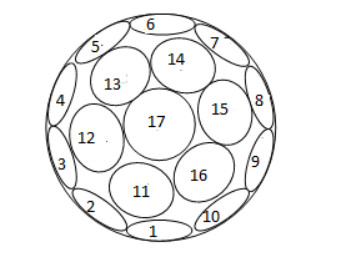
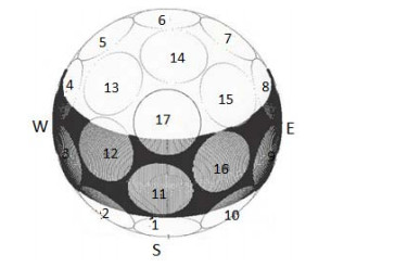
Appelbaum J, Weiss Y (1999) The packing of circles on a hemisphere. Meas Sci Technol 10: 1015-1019. doi: 10.1088/0957-0233/10/11/307
![]() |
[8] |
Bany J, Appelbaum J (1987) The effect of shading on the design of a field of solar collectors. Sol Cells 20: 201-228. doi: 10.1016/0379-6787(87)90029-9
![]() |
[9] |
Temp RC, Coulson KL (1977) Solar radiation incident upon slopes of different orientations. Sol Energy 19: 179-184. doi: 10.1016/0038-092X(77)90056-1
![]() |
[10] | Klucher TM (1979) Evaluation of models to predict insolation on tilted surfaces. Sol Energy 23: 111-114. |
[11] |
Perez R, Ineichen P, Seal P, et al. (1990) Modeling daylight availability and irradiance componens from direct and global irradiance. Sol Energy 44: 271-289. doi: 10.1016/0038-092X(90)90055-H
![]() |
1. | Citlaly Pérez, Pedro Ponce, Alan Meier, Lourdes Dorantes, Jorge Omar Sandoval, Javier Palma, Arturo Molina, S4 Framework for the Integration of Solar Energy Systems in Small and Medium-Sized Manufacturing Companies in Mexico, 2022, 15, 1996-1073, 6882, 10.3390/en15196882 | |
2. | Alireza Keyanfar, Mohammad Roeintan, Kaveh Gheibi, 2022, Monitoring weather condition based on Near-Field Communication (NFC) system, 978-1-6654-6071-2, 1, 10.1109/MACS56771.2022.10022999 | |
3. | Paolo Amore, Circle packing on spherical caps, 2024, 36, 1070-6631, 10.1063/5.0221997 |
Coefficient ΔG/ΔT (% / ℃) | Irradiance (W/m2) | Temperature range (℃) |
−0.15 | 0÷500 | (−)25÷(+)25 |
−0.40 | 0÷500 | (+)25÷(+)100 |
−0.08 | 500÷1000 | (−)25÷(+)25 |
−0.17 | 500÷1000 | (+)25÷(+)100 |