Review

DNA damage by lipid peroxidation products: implications in cancer, inflammation and autoimmunity

  • Received: 14 December 2016 Accepted: 12 April 2017 Published: 18 April 2017
  • Oxidative stress and lipid peroxidation (LPO) induced by inflammation, excess metal storage and excess caloric intake cause generalized DNA damage, producing genotoxic and mutagenic effects. The consequent deregulation of cell homeostasis is implicated in the pathogenesis of a number of malignancies and degenerative diseases. Reactive aldehydes produced by LPO, such as malondialdehyde, acrolein, crotonaldehyde and 4-hydroxy-2-nonenal, react with DNA bases, generating promutagenic exocyclic DNA adducts, which likely contribute to the mutagenic and carcinogenic effects associated with oxidative stress-induced LPO. However, reactive aldehydes, when added to tumor cells, can exert an anticancerous effect. They act, analogously to other chemotherapeutic drugs, by forming DNA adducts and, in this way, they drive the tumor cells toward apoptosis. The aldehyde-DNA adducts, which can be observed during inflammation, play an important role by inducing epigenetic changes which, in turn, can modulate the inflammatory process.
    The pathogenic role of the adducts formed by the products of LPO with biological macromolecules in the breaking of immunological tolerance to self antigens and in the development of autoimmunity has been supported by a wealth of evidence. The instrumental role of the adducts of reactive LPO products with self protein antigens in the sensitization of autoreactive cells to the respective unmodified proteins and in the intermolecular spreading of the autoimmune responses to aldehyde-modified and native DNA is well documented. In contrast, further investigation is required in order to establish whether the formation of adducts of LPO products with DNA might incite substantial immune responsivity and might be instrumental for the spreading of the immunological responses from aldehyde-modified DNA to native DNA and similarly modified, unmodified and/or structurally analogous self protein antigens, thus leading to autoimmunity.

    Citation: Fabrizio Gentile, Alessia Arcaro, Stefania Pizzimenti, Martina Daga, Giovanni Paolo Cetrangolo, Chiara Dianzani, Alessio Lepore, Maria Graf, Paul R. J. Ames, Giuseppina Barrera. DNA damage by lipid peroxidation products: implications in cancer, inflammation and autoimmunity[J]. AIMS Genetics, 2017, 4(2): 103-137. doi: 10.3934/genet.2017.2.103

    Related Papers:

    [1] Raimund Bürger, Christophe Chalons, Rafael Ordoñez, Luis Miguel Villada . A multiclass Lighthill-Whitham-Richards traffic model with a discontinuous velocity function. Networks and Heterogeneous Media, 2021, 16(2): 187-219. doi: 10.3934/nhm.2021004
    [2] Maya Briani, Emiliano Cristiani . An easy-to-use algorithm for simulating traffic flow on networks: Theoretical study. Networks and Heterogeneous Media, 2014, 9(3): 519-552. doi: 10.3934/nhm.2014.9.519
    [3] Mauro Garavello, Roberto Natalini, Benedetto Piccoli, Andrea Terracina . Conservation laws with discontinuous flux. Networks and Heterogeneous Media, 2007, 2(1): 159-179. doi: 10.3934/nhm.2007.2.159
    [4] Raimund Bürger, Kenneth H. Karlsen, John D. Towers . On some difference schemes and entropy conditions for a class of multi-species kinematic flow models with discontinuous flux. Networks and Heterogeneous Media, 2010, 5(3): 461-485. doi: 10.3934/nhm.2010.5.461
    [5] Helge Holden, Nils Henrik Risebro . Follow-the-Leader models can be viewed as a numerical approximation to the Lighthill-Whitham-Richards model for traffic flow. Networks and Heterogeneous Media, 2018, 13(3): 409-421. doi: 10.3934/nhm.2018018
    [6] Adriano Festa, Simone Göttlich, Marion Pfirsching . A model for a network of conveyor belts with discontinuous speed and capacity. Networks and Heterogeneous Media, 2019, 14(2): 389-410. doi: 10.3934/nhm.2019016
    [7] Christophe Chalons, Paola Goatin, Nicolas Seguin . General constrained conservation laws. Application to pedestrian flow modeling. Networks and Heterogeneous Media, 2013, 8(2): 433-463. doi: 10.3934/nhm.2013.8.433
    [8] Raimund Bürger, Stefan Diehl, M. Carmen Martí, Yolanda Vásquez . A difference scheme for a triangular system of conservation laws with discontinuous flux modeling three-phase flows. Networks and Heterogeneous Media, 2023, 18(1): 140-190. doi: 10.3934/nhm.2023006
    [9] Giuseppe Maria Coclite, Lorenzo di Ruvo, Jan Ernest, Siddhartha Mishra . Convergence of vanishing capillarity approximations for scalar conservation laws with discontinuous fluxes. Networks and Heterogeneous Media, 2013, 8(4): 969-984. doi: 10.3934/nhm.2013.8.969
    [10] Wen Shen . Traveling wave profiles for a Follow-the-Leader model for traffic flow with rough road condition. Networks and Heterogeneous Media, 2018, 13(3): 449-478. doi: 10.3934/nhm.2018020
  • Oxidative stress and lipid peroxidation (LPO) induced by inflammation, excess metal storage and excess caloric intake cause generalized DNA damage, producing genotoxic and mutagenic effects. The consequent deregulation of cell homeostasis is implicated in the pathogenesis of a number of malignancies and degenerative diseases. Reactive aldehydes produced by LPO, such as malondialdehyde, acrolein, crotonaldehyde and 4-hydroxy-2-nonenal, react with DNA bases, generating promutagenic exocyclic DNA adducts, which likely contribute to the mutagenic and carcinogenic effects associated with oxidative stress-induced LPO. However, reactive aldehydes, when added to tumor cells, can exert an anticancerous effect. They act, analogously to other chemotherapeutic drugs, by forming DNA adducts and, in this way, they drive the tumor cells toward apoptosis. The aldehyde-DNA adducts, which can be observed during inflammation, play an important role by inducing epigenetic changes which, in turn, can modulate the inflammatory process.
    The pathogenic role of the adducts formed by the products of LPO with biological macromolecules in the breaking of immunological tolerance to self antigens and in the development of autoimmunity has been supported by a wealth of evidence. The instrumental role of the adducts of reactive LPO products with self protein antigens in the sensitization of autoreactive cells to the respective unmodified proteins and in the intermolecular spreading of the autoimmune responses to aldehyde-modified and native DNA is well documented. In contrast, further investigation is required in order to establish whether the formation of adducts of LPO products with DNA might incite substantial immune responsivity and might be instrumental for the spreading of the immunological responses from aldehyde-modified DNA to native DNA and similarly modified, unmodified and/or structurally analogous self protein antigens, thus leading to autoimmunity.


    Traffic flow models based on scalar conservation laws with continuous flux functions are widely used in the literature. For a general presentation of the models, we refer to the books [11,12,23] and the references therein. Extensions to road traffic networks have been also established. We mention in particular the contributions [6,15], where the authors introduce the coupled network problem and show the existence of solutions. Within this article, we are concerned with the special case of scalar conservation laws with discontinuous flux in the unknown that are motivated in the traffic flow theory by the observation of a gap between the free flow and the congested flow regime [4,5,8]. This phenomenon generates an interesting dynamical behavior called zero waves, i.e., waves with infinite (negative) speed but zero wave strength, and has been investigated in recent years either from a theoretical or numerical point of view, see for instance [2,19,20,22,24] or more generally [1,3,7,13].

    To the best of our knowledge, the study of scalar conservation laws with discontinuous flux functions on networks is still missing in the traffic flow literature. However, in the context of supply chains with discontinuous flux such considerations have been already done [10,14]. We remark that supply chain models differ essentially from traffic flow models due to simpler dynamics and different coupling conditions.

    In this work, we aim to derive a traffic network model, where the dynamics on each road are governed by a scalar conservation law with discontinuous flux function in the unknown. For simplicity, we restrict to piecewise linear flux functions. Special emphasis is put on the coupling at junction points to ensure a unique admissible weak solution. In particular, we focus on dispersing junctions where the number of incoming roads does not exceed the number of outgoing roads and merging with two incoming and one outgoing road. The latter type of junction can be extended to the case of multiple incoming roads and a single outgoing one. In order to construct a suitable numerical scheme that is not based on regularization techniques we adapt the splitting algorithm originally introduced in [22]. Therein, the discontinuous flux is decomposed into a Lipschitz continuous flux and a Heaviside flux such that a two-point monotone flux scheme, e.g., Godunov, can be employed in an appropriate manner. This algorithm has been studied in [22] for the case of a single road only. However, in the network case, multiple roads with possibly disjunctive flux functions need to be considered at a junction point to ensure mass conservation. Hence, the key challenge is to determine the correct flux through the junction in an appropriate manner. Therefore, a detailed case distinction in accordance with the theoretical investigations is provided for the different types of junctions. The numerical results validate the proposed algorithm for some relevant network problems.

    The paper is organized as follows: in Section 2 we discuss the basic model and Riemann problems which permit to derive an exact solution. We extend the modeling framework to networks in Section 3 and focus on the coupling conditions. In Section 4, we introduce how the splitting algorithm [22] can be extended to also deal with the different types of junctions. Finally, we present a suitable discretization and numerical simulations in Section 5.

    In this section, we briefly recall the case of the Lighthill-Whitham-Richards (LWR) model [18,21] on a single edge with a flux function having a single decreasing jump at u[0,umax] that has been intensively studied in e.g., [19,22,24]. The shape of this flux function is inspired by empirical research which suggest that the fundamental diagram is of a reverse λ shape and consist of a free flow area and a drop to a congested area, see [4,5,8].

    Following [22], we consider the scalar conservation law Eq (2.1),

    {ut+f(u)x=0,(x,t)(a,b)×(0,T)=:ΠT,u(x,0)=u0(x)[0,umax],x(a,b),u(a,t)=r(t)[0,umax],t(0,T),u(b,t)=s(t)[0,umax],F(t)˜f(s(t)),t(0,T). (2.1)

    More precisely the flux function is defined as follows Eq (2.2),

    f(u)={f1(u) ˆ=Flux1,ifu[0,u],f2(u) ˆ=Flux2,ifu(u,umax]. (2.2)

    We denote f1(u)=f(u) and f2(u)=f(u+), where f(u)>f(u+). In order to assign a single numerical value to f(u) we arbitrarily define f(u)=f(u). One example is shown in Figure 1. The jump has magnitude

    α:=f(u)f(u+). (2.3)
    Figure 1.  An example for a piecewise linear discontinuous flux function with discontinuity at u, cf. [19].

    As usual we require for the flux function f:[0,umax]R+ with f(0)=f(umax)=0 and in addition, we assume f1 to be linear increasing and f2 linear decreasing.

    As in [22], the multivalued version of f is defined by Eq (2.4),

    ˜f(u)={f(u),u[0,u),[f(u+),f(u)],u=u,f(u),u(u,umax]. (2.4)

    Finally, we have to discuss the imposed boundary conditions at x=b in Eq (2.1). Due to the flux discontinuity we have a non-standard boundary condition F(t)˜f(s(t)). If the boundary condition at the right is s(t)u, then the additional boundary condition is redundant, i.e., F(t)=f(s(t)). Otherwise, if s(t)=u, we have to choose between two possible flux values ˜f(u){f(u+),f(u)}. Then, the function F assigns a flux value to u(b,t)=s(t) according to [22]

    F(t)={f(u),ifthetrafficaheadofx=bisfreeflowing,f(u+),ifthetrafficaheadofx=biscongested. (2.5)

    The state of traffic ahead of x=b is additional information that is determined independently from the other data of the problem.

    Remark 2.1. [22,Remark 1.3] We note that for the boundary condition at the left end the state of traffic ahead of x=a is known from the start values. Hence, no additional boundary conditions are necessary.

    The following assumptions are important for the proof of existence and uniqueness of solutions.

    Assumption 2.2. [22,Assumption 1.1] The initial data satisfies u0(x)[0,umax] for x(a,b) and u0BV([a,b]). The boundary data satisfies r(t),s(t)[0,umax] for t[0,T], and r,sBV([0,T]).

    A weak solution is intended in the following sense:

    Definition 2.3 [22,Definition 1.1] A function uL(ΠT) is called a weak solution to the initial-boundary value problem (2.1) if there exists a function vL(ΠT) satisfying

    v(x,t)˜f(u(x,t))a.e.

    such that for each ψC10((a,b)×[0,T)),

    T0ba(uψt+vψx)dxdt+bau0(x)ψ(x,0)dx=0.

    As usual, weak solutions do not lead to a unique solution and additional criteria are necessary to rule out physically incorrect solutions. In particular, the discontinuity of the flux prohibits from directly using the classical approaches. Note that in [22] an adapted version of Oleinik's entropy condition [9] is used to single out the correct solution, while in [24] the convex hull construction [17] is used to construct solutions to Riemann problems.

    Here, we will concentrate on the convex hull construction. For completeness we will shortly recall the solutions to Riemann problems considered in [24] as they are essential in order to construct a Riemann solver at a junction.

    We consider a Riemann problem with initial data (uL,uR) and its exact solution. For simplicity we will focus on a piecewise linear flux function as in [24] and in Figure 1. The exact solution is then derived with a regularization of the flux and the convex hull construction. As regularizations are not unique we choose a simpler regularization than the one in [24]. In fact, we use the regularization introduced in [19] for a piecewise quadratic flux function and apply it to the piecewise linear flux function. In the following we simply recall the results from [19] in case of a linear flux function for the sake of completeness and in order to understand better the upcoming analysis. Note that the the results also coincide with the ones of [24].

    We consider the following flux function by Eq (2, 6),

    f(u)={d1u+d0,xu(Flux1),e1u+e0,x>u(Flux2) (2.6)

    with the regularized flux function given by Eq (2.7),

    fϵ(u)={f1(u)=d1u+d0,0uu,fϵmid(u)=1ϵ(f1(u)fϵ2(u+ϵ))(uu)+f1(u),u<u<u+ϵ,fϵ2(u)=e1u+e0,u+ϵ<uumax. (2.7)

    We define uϵ:=u+ϵ. An example of the regularization is shown in Figure 2. Even though the regularization differs slightly from the one used in [24], the different cases to consider and the approach to solve the Riemann problems are completely analogous. We refer to [24,Section 3] for further details. We define h:[0,umax]R to be a function connecting the points (u,f(u+)) and the initial value lying on Flux 2. In addition, γ denotes the intersection of h and Flux 1, see also Figure 3. The point γ distinguishes the cases 3 and 4 in the following discussion.

    Figure 2.  Example of the regularization of a piecewise linear flux function.
    Figure 3.  The dotted line shows the function h, connecting (u,f(u+)) and uR. The value γ is the intersection point.

    Case 1: Either uL<u,uR<u or uL>u,uR>u

    This case corresponds to the classical case of solving Riemann problems, where the solution consists of a single rarefaction wave or shock, see [17].

    Case 2: uR<u<uL

    By using the smallest convex hull approach the solution consists of a contact line following f(u), connecting uR and u and a shock, connecting u and uL. The speed of the contact discontinuity is given by d1>0 and the speed of the shock can be calculated with the Rankine-Hugoniot condition, i.e.,

    s=f(uL)f(u)uLu<0,

    where we recall that f(u)=f(u) holds. The exact solution is then given by Eq (2.8),

    u(x,t)={uL,ifx<st,u,ifstxd1t,uR,ifx>d1t. (2.8)

    Case 3: γ<uL<u<uR

    Here, the solution is given by a shock connecting uL and u and contact discontinuity reconnecting it to uR. The speed of the shock equals:

    s=f(u+)f(uL)uuL<0.

    Note that due to uL<uR the convex hull construction chooses the flux f(u+) at u. The contact discontinuity connecting u and uR moves at the speed e1<0. Hence,

    u(x,t)={uL,ifx<st,u,ifstxe1t,uR,ifx>e1t. (2.9)

    Case 4: uL<u<uR and γuL

    In this case, we get only one shock connecting uL and uR as a solution due to the condition γuL. The speed of the shock can be calculated by the Rankin-Hugoniot condition. The exact solution is given by Eq (2.10),

    u(x,t)={uL,ifx<st,uR,ifxst. (2.10)

    Remark 2.4. As aforementioned in [19] Riemann solutions for piecewise quadratic discontinuous flux functions are derived. They also cover the case of a piecewise linear flux function if the quadratic terms are zero. For a general quadratic discontinuous flux, the solutions are more involved since no contact discontinuities occur.

    Up to now, we have not addressed the case, where one of the boundary conditions equals the critical density u. In this situation so called zero waves can occur, see [24]. Those waves travel with speed O(1ϵ) from right to left and have strength O(ϵ), depending on the regularization parameter ϵ. Although they have no strength, information can be exchanged between Riemann problems lying next to each other influencing the solution. For more details on the origin of zero waves in the context of traffic flow we refer to [24]. In particular, they arise when double Riemann problems are considered. For a detailed discussion of these double Riemann problems we refer to [24,Section 4].

    Next, we focus on networks where we allow for discontinuous flux functions. The key idea is to consider the regularized flux function fϵ and take the limit ϵ0 to obtain results for the original problem at intersections. In doing so, the standard approaches can be directly applied to the regularized flux function fϵ.

    We start with a short introduction to the network setting. For more details on traffic flow network models we refer the reader to [11] and the references therein.

    Let G=(V,E) be a directed finite graph consisting of a nonempty set V of vertices and a nonempty set of edges E representing the roads. We denote by δv and δ+v the set of all incoming and outgoing edges for every vertex vV. Every edge eE is interpreted as an interval Ie=(ae,be)R representing the spatial extension of the road e. For all edges e, which do not discharge into a vertex, i.e. evVδv, we set an infinite road length by be=+. Analogously, for all edges e, which do not originate from a vertex, i.e. evVδ+v, we set an infinite road length by ae=.

    We call the couple (I,V) with I={Ie:eE} a road network.

    In order to derive the network solution, we restrict to the description of a single junction vV. Hence, from now on we consider a fixed junction with n incoming and m outgoing roads. Then, we need additional information how vehicles are distributed from one road to another. Hence, we need to define a distribution matrix A[0,1]n×m as in [11]:

    A=(β1,1β1,mβn,1βn,m).

    To conserve the mass we assume mj=1βi,j=1 for every i{1,,n}. Furthermore, some technical assumptions on the distribution matrix are necessary which can be found in ref. [11] (Eq (4.2.4)). These assumptions are necessary to obtain unique solutions at the junction for the case nm. Following ref. [11] (definition 4.2.4) and definition 2.3, weak solutions at a junction are intended in the following sense

    Definition 3.1 (Weak solution at a junction). Let vV be a vertex with n incoming and m outgoing roads, represented by the intervals Iin1,Iinn and Iout1,Ioutn. A weak solution at the junction v is a collection u and w of functions uini:Iini×R0R, wini:Iini×R0R with wini(x,t)˜f(uini(x,t)) a.e., where i=1,,n, uoutj : Ioutj×R0R and woutj:Ioutj×R0R with woutj(x,t)˜f(uoutj(x,t)) a.e., where j=1,,m, respectively, such that

    ni=1(T0Iini(uini(x,t)tϕini(x,t)+wini(x,t)xϕini(x,t))dxdt)+mj=1(T0Ioutj(uoutj(x,t)tϕoutj(x,t)+woutj(x,t)xϕoutj(x,t))dxdt)=0,

    for every collection of test functions ϕiniC10((aini,bini]×[0,T]),i=1,,n and ϕoutjC10((aoutj,boutj]×[0,T]),j=1,,m, satisfying

    ϕini(bini,)=ϕoutj(aoutj,),xϕini(bini,)=xϕoutj(aoutj,),

    for i1,nandj1,,m.

    Additionally, in order to get unique solutions, we will consider the following concept of admissible solutions, which adapts ref. [11] (rule (A) and (B), p. 81) to the discontinuous setting:

    Definition 3.2 (Admissbile Weak Solution). We call u and w (as defined in definition 3.1) an admissible weak solution at a junction vV with the corresponding distribution matrix A if

    1. uini(,t)BV(Iini),uoutj(,t)BV(Ioutj)foralli,j,

    2. u and w constitute a weak solution at the junction v,

    3. woutj(aoutj+,t))=ni=1βi,jwini(bini,t))forallj=1,,mandt0,

    4. ni=1wini(bini,t)) is maximal subject to 2. and 3.

    In particular, the maximization of the inflow with respect to the distributions parameters and the technical assumption [11] guarantee the uniqueness of solutions for a continuous flux.

    If n>m, that means more incoming than outgoing roads, we need so-called right of way parameters which prescribe in which order the vehicles are going to drive. We consider the special case n=2 and m=1. Let CR denote the amount of vehicles that can move on the road. The right of way parameter q(0,1) describes the following situation: If not all vehicles can move to the outgoing road, then qC is the amount of vehicles that enter from the first and (1q)C the amount from the second road. If there are more roads, we need to define several right of way parameters.

    For solving the maximization problems imposed by the definition 3.2 so-called supply and demand functions can be used, see [16]. The demand describes the maximal flux the incoming road wants to send. In contrast, the supply describes the maximal flux the outgoing road is able to absorb. The definition of the supply and demand functions of the regularized function is straightforward. As f(u){f(u+),f(u)} is not unique, we have to consider the limit for ϵ0 to determine the correct values of the supply and demand for the discontinuous flux function. Nevertheless, it becomes apparent that the maximal flux in both cases is given by f(u). This leads to the following definition:

    Definition 3.3. For a network with flux function f having a discontinuity at u, the demand is given by

    D(u)={f(u),u[0,u),f(u),u[u,umax]. (3.1)

    On the contrary, the supply reads as

    S(u)={f(u),u[0,u),f(u),u(u,umax] (3.2)

    and

    S(u)={f(u),freeflowing,f(u+),congested. (3.3)

    Remark 3.4. If we consider the regularized flux function fϵ, the definition of supply and demand function is completely analogous by replacing f with fϵ.

    In order to show existence and uniqueness in the discontinuous case we need to define an additional function. For a regularized flux function we notice that for every flux value, we get two different density values, see left picture in Figure 4. As different density values lead to different solutions, we need to be able to distinguish them and choose the correct solution. In the continuous or regularized case a mapping usually called τ is used to determine the density values for which the flux values coincide, see also left picture in Figure 4 and ref. [11] (definition 3.2.6) for the precise definition of τ. This situation becomes more complicated for the discontinuous flux functions. For ϵ0 and f(u)>f(u+), the corresponding density value given by τ can converge to the discontinuity area. This situation is pictured in Figure 4 on the right. Therefore, we need to adapt the definition of the mapping τ to also cover this case and determine the corresponding density value. This mapping is defined in the following and is denoted by η. For readability, we also define as an abbreviation f1+:=f1(f(u+)).

    Figure 4.  The left panel shows the regularized version. The right panel shows the discontinuous flux f. The grey area displays the interval, where f(η(u))f(u) and η(u)=u.

    Definition 3.5. Let the function η:[0,umax][0,umax] satisfy:

    1. f(η(u))=f(u) for every u([0,f1+][u,umax]) and η(u)u for every u([0,f1+](u,umax]).

    2. For u(f1+,u) it holds, η(u)=u and f(η(u))=f(u).

    Note that if u(f1+,u), the flux value is given by f(u)(f(u+),f(u)).

    Remark 3.6. We note that the mapping τ from ref. [11] (definition 3.2.6) is in principle given by the first statement in definition 3.5 with the separated interval [0,f1+][u,umax] being replaced by [0,umax]. Hence, the only difference between τ and η lies in the treatment of u(f1+,u).

    Now, we present a Riemann solver for two types of junctions. First, we consider a junction with n incoming and m outgoing roads with nm, second, a junction with n=2 incoming and m=1 outgoing roads. For the continuous case the existence of solutions satisfying in particular the definition 3.2 has been shown in [11]. Since the continuous flux is not multivalued, the definition in 3.2 coincides with ref. [11] (Definition 4.2.4). As we have seen in Section 2.1, the solution to a Riemann problem may produce more than one wave. In order to have a well-defined network problem it is important that the waves produced at the junction have negative speed on the incoming and positive speed on the outgoing roads. This is ensured by the following theorem:

    Theorem 3.7. Let wV be a junction with n incoming and m outgoing roads with nm. For every constant initial datum uini,0,uoutj,0[0,umax], i=1,,n, j=1,,m, there exists a unique admissible weak solution u in the sense of definition 3.2. Moreover, for the incoming road the solution is given by the wave (uini,0,uini), i=1,,n and for every outgoing road the solution is the wave (uoutj,0,uoutj),j=1,,m, where

    uini{{uini,0}(η(uini,0),umax],ifuini,0[0,f1+],{uini,0}[u,umax],ifuini,0(f1+,u),[u,umax],ifuini,0[u,umax], (3.4)

    and

    uoutj{[0,u],ifuoutj,0[0,u),[0,u],ifuoutj,0=uandfreeflowing,{u}[0,f1+),ifuoutj,0=uandcongested,{uoutj,0}[0,η(uoutj,0)),ifuoutj,0(u,umax]. (3.5)

    Proof. Using the definition of the supply and demand functions in definition 3.3 and the results from [12,section 5.2.3] we can follow the proof of [12,theorem 5.1.2] and uniquely determine the inflows which maximize the flux through junctions subject to the distribution parameters. It remains to show that by the choice of the density values the correct waves are induced.

    We start with considering the outgoing roads. If uoutj,0[0,u), the choice uoutj[0,u] produces the classical case of a shock or contact discontinuity, both with the positive speed d1, since the flux is a linear increasing function. If uoutj,0=u, we need to know if the traffic ahead is congested or not in order to determine the correct flux value of u and the corresponding density. In particular, we are now concerned with a double Riemann problem by uoutj, uoutj,0=u and the information about the traffic ahead. By the analysis done in [24,Section 4] the choices of uoutj give rise to waves with positive velocities, even though the velocities differ depending on the traffic situation. Note that the free flowing case corresponds to case 1 in [24,Section 4] and the congested case to case 2. In particular, in the latter case foutjf(u+)=f(u) holds such that the solution is a shock with velocity always greater or equal to zero, compare also case 4 of Section 2.1.

    For uoutj,0(u,umax] we need to choose the density uoutj{uoutj,0}[0,η(uoutj,0)) which corresponds to the incoming flux. Here, we are in case 4 of Section 2.1, as uoutj,0<γ, such that the solution is a shock with positive velocity.

    On the contrary, considering the incoming roads and uini,0[0,f1+], the choice uini{uini,0}(η(uini,0),umax] also corresponds to case 4, but this time the shock has a negative velocity.

    Now, let uini,0(u,umax] and fini denote the uniquely determined inflow. If fini<f(u+), the choice uini(u,umax] corresponds to the solution of a Riemann problem with a linear decreasing function and hence either a shock or contact discontinuity with negative velocity. On the contrary if finif(u+), we choose uini=u. Here, the convex hull reconstruction induces a shock as a solution with velocity

    s=finif(uini,0)uuini,0<0.

    Further, if uini,0=u, we would normally also need to consider a double Riemann problem for which we would need the information of boundary data of the incoming roads. Nevertheless, the solutions at the junction are the same. As can be seen in [24,section 4] cases 2 and 4, if fini<f(u+) the choice uini(u,umax] induces a contact discontinuity with negative velocity as the solution at the junction. If finif(u+) we choose uini=u which gives a constant solution.

    Now, let us turn to the remaining case of uini,0(f1+,u). Again the solution depends on the inflow. If fini<f(u+), the choice of uini{uini,0}(u,umax] induces negative waves. Nevertheless, depending on uini,0>γ or uini,0γ we are either in case 3 or case 4 of Section 2.1. Even though case 3 induces two waves, all have a negative velocity. If finif(u+), choosing uini=u gives a shock with velocity

    s=finif(uini,0)uuini,00,

    as fini is bounded from above by f(uini,0) due to the definition of the demand.

    Hence, the choices of the densities induce the correct waves.

    Now, we consider the case of more incoming than outgoing roads. Exemplary, we study the 2–to–1 situation, even though the results can be easily extended to the n–to–1 case. We assume that a right of way parameter q is given and the unique density of the discontinuous flux can be determined according to the following theorem:

    Theorem 3.8. Let wV be a junction with n=2 incoming and m=1 outgoing roads with a right way parameter q(0,1). For every constant initial datum uini,0,uout1,0[0,umax] with i{1,2}, there exists a unique admissible weak solution u in the sense of definition 3.2. Moreover, for every incoming road i the solution is given by the wave (uini,0,uini) and for the outgoing edge the solution is the wave (uout1,0,uout1), where

    uini{{uini,0}(η(uini,0),umax],ifuini,0[0,f1+],{uini,0}[u,umax],ifuini,0(f1+,u),[u,umax],ifuini,0[u,umax], (3.6)

    and

    uout1{[0,u],ifuout1,0[0,u),[0,u],ifuout1,0=uandfreeflowing,{u}[0,f1+),ifuout1,0=uandcongested,{uout1,0}[0,η(uout1,0)),ifuout1,0(u,umax]. (3.7)

    Proof. Following [11,Section 3.2.2], the flux values at the junction can be calculated with the following steps:

    1. Calculate the maximal possible flux fmax=min{D(uin1,0)+D(uin2,0),S(uout1,0)}.

    2. Consider the right of way parameter and the flux maximization and calculate the intersection P=(qfmax,(1q)fmax).

    3. If P is in the feasible area Ω={z[0,D(uin1,0)]×[0,D(uin2,0)]:z1+z2fmax}, set (z1,z2)=P. If not, determine the point in Ω{(z1,z2):z1+z2=fmax} which is the closest to the line z2=(1q)/qz1.

    4. The flux values are given by fin1=z1, fin2=z2, fout1=z1+z2.

    Completely analogous to theorem 3.7 we can show that the choice of the densities admits the correct wave speeds.

    The Riemann solutions proposed in theorem 3.7 and theorem 3.8 are the key ingredients for the splitting algorithm on networks in the next section.

    Different problems might occur when designing a numerical scheme for a conservation law with discontinuous flux. However, the main difficulties are induced by the zero waves. Since these waves have infinite speed, the regular CFL condition is scaled by the regularization parameter ϵ. This leads to very inefficient step sizes and high computational effort. Possible ways to avoid using the regular CFL condition are implicit methods [20] or the splitting algorithm introduced in [22], see also [2]. In this section we recall the main ideas of the splitting algorithm and also present its extension to networks.

    We consider a flux function f with discontinuity at u, which satisfies assumption 2.2. The jump has magnitude α=f(u)f(u+). The main idea of the splitting algorithm is to split the discontinuous function f into two parts, namely p and g, such that f(u)=p(u)+g(u). Here, g is a piecewise constant function defined by

    g(u)=αH(uu),

    where H denotes the Heaviside function. This function extracts the jump from the function f. In addition, we define p(u)=f(u)g(u). Hence, p is continuous and can be used for numerical algorithms. An example can be seen in Figure 5.

    Figure 5.  Based on [22,Figure 1]. The left panel shows the discontinuous flux function, the right panel shows the splitted version. The dotted line represents the piecewise constant function g, the solid line shows the continuous function p.

    This case has been already treated in [22] and will be the basis for the splitting algorithm on networks. When solving the scalar conservation law (2.1) on a single road, the boundary value in the case s(t)=u is not unique. In the continuous case, the flux value is determined by F(t) in Eq (2.5). When splitting the function f, the discontinuity is shifted to the function g. So analogously, we define the multivalued version of g in order to be able to assign a flux value in the critical case, i.e.,

    ˜g(u)={0,u[0,u),[α,0],u=u,α,u(u,umax]. (4.1)

    Furthermore, we define G(t)˜g(s(t)). It holds,

    F(t)=f(u)G(t)=0,F(t)=f(u+)G(t)=α. (4.2)

    Additionally to the assumptions 2.2, we assume:

    Assumption 4.1. [22,Assumption 1.1] The initial data satisfies u0(x)[0,umax] for x(a,b), u0BV([a,b]) and g(u0)BV([a,b]). We also assume that G(t)[α,0] for t[0,T], and GBV([0,T]).

    Remark 4.2. We emphasize that the original splitting algorithm for a single road [22] is not limited to piecewise linear discontinuous flux functions. Another prominent example might be concave piecewise quadratic flux functions with discontinuity again at u, cf. [19,22,24].

    Then, we are able to handle the flux function p and the jump g separately. As usual, we discretize the domain ΠT by a spatial mesh and a temporal mesh. Let Δx denote the spatial and Δt the temporal step size. We define the grid constant via

    λ=ΔtΔx.

    For an integer KN the grid size is given by Δx=baK+1 and the grid points by xk=a+kΔx. Further, we define the K disjunct intervals Ik=[xkΔx2,xk+Δx2) and K={1,K} and K+={0,K+1}. The time steps are defined by tn=nΔt, for n=0,1,,N. The value NN is chosen such that the time horizon fulfills T[tN,tN+Δt).

    As the algorithm splits the function f into two parts, f(u)=p(u)+g(u), every step of the algorithm consists of two half steps. Here, the first half step corresponds to approximately solving ut+g(u)x=0 denoted by Un+12ku(xk,tn). Consequently, the second step approximates ut+p(u)x=0 and is denoted by Unku(xk,tn).

    We denote the backward spatial difference by ΔUnk=UnkUnk1 and the forward spatial difference by Δ+Unk=Unk+1Unk. The initial values are denoted by U0k=u0(xk), the boundary values by

    rn=rn+12=r(tn),Un+120=Un0=rnsn=sn+12=s(tn)Un+12K+1=UnK+1=sn.

    The function g covers the issue of s(tn)=u. We define

    gn+12K+1=gnK+1=G(tn)={0,ifs(tn)<u,0,ifs(tn)=u,trafficaheadofx=bisfreeflowing,α,ifs(tn)=u,trafficaheadofx=biscongested,α,ifs(tn)>u. (4.3)

    That means, we can describe the boundary value F(t) via G(t). For the splitting algorithm in its original fashion [22] we additionally need the following function.

    Definition 4.3 [22,Eq (3.7)] Let G(z):=zλg(z) with grid constant λ and ˜G its multivalued version. The function ˜G is strictly increasing and has a unique inverse, z˜G1(z), which is a single valued function. It is Lipschitz continuous and nondecreasing. It holds, 0˜G1(z)z. The functions are given by

    ˜G(u)={u,u[0,u),[u,u+λα],u=u,u+λα,u(u,umax], ˜G1(u)={u,u[0,u),u,u[u,u+λα),uλα,u[u+λα,umax+λα].

    The splitting algorithm [22] can be then expressed as

    {{Un+1/2k=˜G1(Unkλgn+1/2k+1),k=K,K1,,1,gn+1/2k=(Un+1/2kUnk+λgn+1/2k+1)/λ,k=K,K1,,1,Un+1k=Un+1/2kλΔpg(Un+1/2k+1,Un+1/2k), kK. (4.4)

    Note that the first half step, which includes the first two equations, is implicit. Nevertheless, instead of solving a nonlinear system of equations, the equation can be solved backwards in space starting with k=K. The last equation in (4.4) uses the Godunov scheme for the second half step which flux function is denoted by pg.

    We note that for the implicit equation a CFL condition is not needed, but it is required for the third step. As p is continuous, we can use the standard CFL condition of the Godunov scheme. Note that similar to [22] also other two-point monotone schemes, e.g., the Lax-Friedrichs method, can be used.

    As shown in [22,Theorem 5.1] the splitting algorithm (4.4) converges to a weak solution of Eq (2.1). However, obtaining a similar statement about weak entropy solutions is still an open problem.

    The key idea to numerically solve such discontinuous conservation laws on networks is to use the splitting algorithm only on the roads and determine the correct in- and outflows at the boundaries by the help of the Riemann solver established in, e.g., theorem 3.7. As the splitting algorithm works with flux values, there is no need to compute the exact densities at the junction. Instead we need to know how the solution at the junction influences the flux values. The algorithm for a single junction is depicted in algorithm 1. The general description of the algorithm allows for either junctions with given distribution or right of way parameters. For simplicity, we assume that each road is represented by the same interval (a,b), such that we have Iin1==Iinn=Iout1==Ioutm=(a,b).

    Remark 4.4. Note that this simplification enables the use of the same grid points on each road which spares further sub- or superindices. However, the algorithm can be easily adapted to different road lengths.

    We assume in the following that the space and time grid is the same as in the previous subsection. The approximate solutions are denoted by Un,ini,kun,ini,k(xk,tn) for i=1,,n and Un,outj,kun,outj,k(xk,tn) for j=1,,m. The half steps are denoted accordingly. We assume that the initial values uini,0(x) and uoutj,0(x) and the boundary values uini,0(a,t) and uoutj,0(b,t) are given. Then, we can directly set the starting values as U0,ini,k=uini,0(xk) for i=1,,n and U0,outj,k=uoutj,0(xk) for j=1,,m. The left boundary values for the incoming roads are given by Un,ini,0=uini,0(a,tn) and the right boundary values for the outgoing roads by Un,outj,0=uoutj,0(b,tn). The missing boundary data, i.e. the right one for the incoming road and the left one for the outgoing road, are determined by the flux values at the junction.

    The overall strategy of the splitting algorithm on a network consists of three important steps:

    1. Solve the optimization problem induced by definition 3.2 (in particular item 4) at the junction to calculate the flux values fini,foutj with the discontinuous flux f.

    Here, it is crucial to use the discontinuous flux function f when calculating demand and supply at the junction, which are necessary for the optimization problem, since otherwise not only the flux values can be different but also the decision whether supply or demand is active. Therefore, in line 6, we need to compute first the fluxes at the junction with the original discontinuous flux function f.

    These flux values bring us now to:

    2. Consider the corresponding density values at the junction applying either theorem 3.7 or theorem 3.8 depending on the type of junction. If the density value is greater or equal than u, i.e., the road is congested, the flux value needs to be adjusted. Hence, we determine adjusted flux values fin/outadj..

    Table Algorithm 1.  Splitting algorithm for a fixed junction of dispersing or merging type.
    Require: number of incoming roads n, number of outgoing roads m, distribution matrix A, (right of way parameters), flux f, discontinuity u, jump magnitude α, interval boundaries a, b, number of grid points K, time step size Δt, initial values uini,0(x) and uoutj,0(x), boundary values uini,0(a,t) and uoutj,0(b,t)
    Ensure: approximate solutions Un,ini,k and Un,outj,k
    1: Initilization:
    2: Δx=(ba)/(K+1) and λ=Δt/Δx,
    3: U0,ini,k=uini,0(xk) for i=1,,n, U0,outj,k=uoutj,0(xk) for j=1,,m
    4: Un,ini,0=uini,0(a,tn), Un,outj,0=uoutj,0(b,tn)
    5: for n=0,,N1 do
    6:    Solve the by definition 3.2 induced optimization problem at the junction based on the flux f, which gives the fluxes fini, foutj
    7:    Compute the densities at the junction with an appropriate Riemann solver
    8:    Compute the adjusted flux values for the incoming roads fini,adj.
    9:    for i=1,,n do
    10:      gn+1/2,ini,K+1=gn,ini,K+1=finifini,adj.
    11:     for k=K,K1,,1 do
    12:        Un+1/2,ini,k=˜G1(Un,ini,kλgn+1/2,ini,k+1)
    13:       gn+1/2,ini,k=(Un+1/2,ini,kUn,ini,k+λgn+1/2,ini,k+1)/λ
    14:      end for
    15:     pg(Un+1/2,ini,K+1,Un+1/2,ini,K)=fini,adj.
    16:     for kK do
    17:        Un+1,ini,k=Un+1/2,ini,kλΔpg(Un+1/2,ini,k+1,Un+1/2,ini,k)
    18:      end for
    19:    end for
    20:    for j=1,,m do
    21:      Compute gn+1/2,outj,K+1=gn,outj,K+1 as in (4.3)
    22:      for k=K,K1,,1 do
    23:        Un+1/2,outj,k=˜G1(Un,inj,kλgn+1/2,outj,k+1)
    24:        gn+1/2,outj,k=(Un+1/2,outj,kUn,outj,k+λgn+1/2,outj,k+1)/λ
    25:     end for
    26:      pg(Un+1/2,inj,1,Un+1/2,outj,0)=foutj
    27:      for kK do
    28:        Un+1,outj,k=Un+1/2,outj,kλΔpg(Un+1/2,outj,k+1,Un+1/2,outj,k)
    29:      end for
    30:    end for
    31: end for

     | Show Table
    DownLoad: CSV

    Using the calculated (unadjusted) flux values from step one, we can determine the densities at the junction with the help of the appropriate Riemann solver (theorem 3.7 and Eqs (3.4)–(3.5) or theorem 3.8 and Eqs (3.6)–(3.7)) at the junction (line 7). Then, these density values can be used to calculate the corresponding flux value of p to get the boundary values and decide about an adjustment. This means that if the density given by the Riemann solver suggests that the traffic ahead is free flowing, no adjustment needs to be made - as the flux value already lies on p. If the traffic ahead is congested we take the flux value on the curve p for the corresponding density value and not its original flux value on the curve f. Both the first step, i.e solving the optimization problem at the junction, and the second step, i.e., how to adjust the flux, strongly depend on the junction type. Hence, we postpone a detailed discussion to the following subsections, in which we will consider the 1–to–1, 1–to–2 and 2–to–1 case in more detail.

    In addition, the first steps give us all the ingredients for the final step:

    3. Away from the junction, the splitting algorithm can be used. At the junction itself, the adjusted fluxes are used to determine the missing boundary data.

    The adjusted flux values from the previous step are important for the second half step (line 17 or 28) of the splitting algorithm which uses a Godunov type scheme based on p. Here, the missing fluxes in and out of the junction the Godunov scheme needs are simply given by these adjusted flux values. The flux values can be used directly as boundary conditions, see lines 15 and 26, and the exact density values are not needed for the scheme.

    Further boundary data is needed in the first half step of the algorithm, lines 12–13 and 23–24. Here, we start with k=K to avoid solving a nonlinear equation system. For example, the value gn,outj,K+1 is determined by the density value at the boundary. Nevertheless, for every outgoing road the boundary values are known and the value gn,outj,K+1 can be determined as before in Eq (4.3). However, for the incoming road, i.e., for gn,ini,K+1, the density value at the junction is necessary. From the adjustment made in step two we know whether the traffic ahead is congested or not. In addition, instead of working with the exact density values at the junction directly, we can also use the adjusted flows computed in the second step (or line 8). Here, we can simply compute the boundary value gn,ini,K+1 by the difference between the fluxes calculated with f (before adjustment) and the ones with p (after adjustment), i.e.,

    gn+1/2,ini,K+1=gn,ini,K+1=finifini,adj. (4.5)

    Note that the definition of gn,ini,K+1 in Eq (4.5) is slightly different in comparison to Eq (4.3) or for the outgoing roads. Nevertheless, if the density value on the incoming road is smaller than u, gn,ini,K+1 equals zero (no adjustment needs to be made) and if it is greater u, it equals α. Only in the case the density value equals u the situation is more involved, as the traffic on the incoming road can be congested and f(u)>fin>f(u+) can occur such that we need gn,ini,K+1(α,0).

    Furthermore, we can decrease the computational costs of the algorithm: In the second step (or in line 7 of algorithm 1) the density at the junction is computed. This can be very expensive and hence we aim to avoid this. In the third step we have seen that for the missing boundary data only the adjusted flux values are necessary and not the densities at the junction themselves. Therefore, studying first each junction type in detail allows to determine the corresponding flux values based on the density values and the supply and demand functions and the intermediate expensive step for the computation of the exact densities can be skipped. Hence, we combine the first and second step of the strategy in one single step. In the following, we will study a 1–to–1 junction in detail and present the tailored algorithm. As the strategy is completely analogous for the 1–to–2 junction and 2–to–1 junction, we will only present the algorithms and discuss important properties. The algorithms can then be used to replace the lines 6 to 8 in algorithm 1.

    Remark 4.5. The extension to n–to–1 or 1–to–m junctions follows immediately from the upcoming discussion. For more complex junctions, it is possible to adapt the proposed strategy by studying the different solutions of the optimization problem at the junction.

    Remark 4.6. Further note that the presented strategy and also algorithm 1 can be used for arbitrary junctions and nonlinear discontinuous flux functions once an appropriate Riemann solver similar to theorem 3.7 and 3.8 is established.

    First, we consider a junction with one incoming and one outgoing road in detail. Let uin1,0,uout1,0 be constant initial values. The flux values are given by fin1=fout1=min{D(uin1,0),S(uout1,0)}. We distinguish the following cases:

    Case A: demand and supply are equal

    There are two different situations depending on the density value of the incoming road where demand and supply can be equal.

    1. uin1,0u: Here, the traffic on the outgoing road needs to be free-flowing or equal to u and the traffic ahead of the outgoing road is free-flowing. Supply and demand equal the maximal possible flux f(u). For these flux values the solution of the Riemann solver on the incoming and outgoing road is given by u. As corresponding flux values already lie on p, we do not need to adjust them.

    2. uin1,0<u: Demand and supply can also be equal, if the number of vehicles the demand wants to send is equal to the number of vehicles the supply can take. Therefore, uin1,0<γ and uout1,0>u need to hold. The solution proposed by the Riemann solver at the junction is the initial condition for each road. Hence, the traffic on the outgoing road stays congested and we need to adjust the flux value on the outgoing road, i.e., fout1,adj=fout1+α. The flux on the incoming road stays free-flowing.

    Case B: supply is restrictive

    If the supply is restrictive, i.e. fin1=fout1=S(uout1,0)<D(uin1,0), the outgoing road cannot take the whole amount of cars, the demand wants to send. From this follows that the traffic on the outgoing road is congested, i.e. uout1,0>u or uout1,0=u and the traffic ahead being congested. This has an effect on the incoming road. Again, we face two situations:

    1. u1,0in<u: Initially, the traffic on the incoming road is free-flowing and the traffic on the outgoing road is congested. As the supply is restrictive, the traffic on the incoming road congests as well, the solution of the Riemann solver is on both roads given by uout1,0. Therefore, we have to adjust the flux value, fin1,adj=fin1+α. In addition, we need to set gn,in1,K+1=α. The outgoing flux needs to be also adjusted, i.e., fout1,adj=fout1+α.

    2. u1,0in>u: If the traffic on the incoming road is congested as well, the solution of the Riemann solver on both roads is again given by uout1,0. This leads to the same adjustments as in the previous case.

    Case C: demand is restrictive

    If the demand is restrictive, the outgoing road is able to take the whole amount of vehicles the demand wants to send. Here, we only have one possible situation for the initial condition on the incoming road:

    1. u1,0inu: The solution of the Riemann problem on each road is now given by uin1,0, such that no adjustment is necessary.

    Note that we have the same flux function on each road. Hence, in the case u1,0in>u either the supply is restrictive or demand and supply are equal.

    The whole procedure is summarized in algorithm 2.

    Table Algorithm 2.  1–to–1 junction.
    Require: Demand D1, Supply S1, flux f, discontinuity u, jump magnitude α
    Ensure: Flux values fin1,fout1
    1: fin1=min{D1,S1}
    2: fout1=fin1
    3: if S1=D1 and D1f(u) then
    4:    fout1=fout1+α
    5: else if S1<D1 then
    6:     fout1=fout1+α
    7:     fin1=fin1+α
    8: end if

     | Show Table
    DownLoad: CSV

    Remark 4.7. Theoretically, the Riemann solver in theorem 3.7 coincides for a 1–to–1 junction with the Riemann solver on a single road. Hence, the procedure described in algorithm 2 leads to the same solution. In contrast to that on the numerical level, the splitting algorithm for a 1–to–1 junction does not exactly coincide with the splitting algorithm used for a single road [22]. The reason for the computational difference is that the splitting algorithm for the 1–to–1 junction considers the exact solution of the Riemann problem at the junction point and hence uses exact values for gn,in1,K+1 while for a single road this value is only approximated using gn,out1,K+1.

    The difference to the 1–to–1 junction is now that we have to consider two supplies. So the case distinctions to determine the flux values are a bit more complex. However, the procedure itself does not change. The details can be seen in algorithm 3.

    We remark that if the inflow on the first road equals the demand and the restriction given by at least one of the supplies, the latter road needs to be congested. The Riemann solver states congestion such that the flux needs to be adjusted. Then, the incoming road either stays free flowing or the solution is given by u. Here, no adjustment is necessary. Note that the conditions Sif(u) are necessary for the specific case of βi=1.

    Table Algorithm 3.  1–to–2 junction.
    Require: Demand D1, Supply S1,S2, distribution parameter β1,β2, flux f, discontinuity u, jump magnitude α
    Ensure: Flux values fin1,fout1,fout2
    1: fin1=min{D1,S1/β1,S2/β2}
    2: fout1=β1fin1,fout2=β2fin1
    3: if fin1=D1 then
    4:    if S1=D1 and S1f(u) then
    5:      fout1=fout1+α
    6:   else if S2=D1 and S2f(u) then
    7:      fout2=fout2+α
    8:    end if
    9: else if fin1=S1/β1 or fin1=S2/β2 then
    10:    if fin1>f(u+) then
    11:     fin1=f(u)
    12:    else
    13:     fin1=fin1+α
    14:    end if
    15:    if S1/β1=S2β2 and S1β1<D1 then
    16:      fout1=fout1+α
    17:      fout2=fout2+α
    18:   else if S1/β1<S2β2 and S1β1<D1 then
    19:      fout1=fout1+α
    20:   else if S2/β2<S1β1 and S2β2<D1 then
    21:      fout2=fout2+α
    22:    end if
    23: end if

     | Show Table
    DownLoad: CSV

    If at least one of the supply restrictions is active, we need to adjust the corresponding flux values as in the 1–to–1 case and the incoming road. Nevertheless, here an interesting case (which is not possible in the 1–to–1 situation) can occur. The solution of the Riemann problem at the incoming road can be given by u and the inflow is in fin1(f(u+),f(u)), see also the proof of theorem 3.7. We need to adjust the flux to p(u)=f(u). Hence, in this case if we use Eq (4.5) the adjustment is between 0 and α. Finally, as in the 1–to–1 case there is no need for an adjustment if the demand is restrictive.

    Recall that for two incoming and one outgoing roads, the maximal possible flux on the outgoing road is given by fmax=min{D(uin1,0)+D(uin2,0),S(uout1,0)}. The corresponding flux values on the incoming roads are always smaller or equal to the actual demand. The algorithm for the corresponding adjusted flux values is listed in algorithm 4.

    Table Algorithm 4.  2–to–1 junction.
    Require: Demand D1, D2, Supply S1, right of way parameter q1,q2, flux f, discontinuity u, jump magnitude α
    Ensure: Flux values fin1,fin2,fout1
    1: fmax=min{D1+D2,S1}
    2: fout1=fmax,z1=q1fmax,z2=q2fmax
    3: if z1>D1 then
    4:   z1=D1,z2=fmaxz2 5: else if z2>D2 then
    6:   z2=D2,z1=fmaxz1
    7: end if
    8: fin1=z1,fin2=z2
    9: if D1+D2=S1 and S1f(u) then
    10:    fout1=fout1+α
    11:else if D1+D2<S1 then
    12:    if S1f(u) then
    13:      fout1=fout1+α
    14:    end if
    15:    if fin1<D1 then
    16:      if fin1>f(u+) then
    17:       fin1=f(u)
    18:      else
    19:       fin1=fin1+α
    20:     end if
    21:    end if
    22:    if fin2<D2 then
    23:      if fin2>f(u+) then
    24:       fin2=f(u)
    25:      else
    26:       fin2=fin2+α
    27:      end if
    28:    end if
    29: end if

     | Show Table
    DownLoad: CSV

    As before, no adjustment is needed when the demand on both roads is smaller than the supply. If the supply is active we might need to adjust the outgoing road and in most cases at least one incoming road. As in the 1–to–2 case, fini can be greater than f(u+) such that the Riemann solver of theorem 3.8 gives u as a solution with the corresponding flux p(u)=f(u) leading to an adjustment smaller than α.

    In this section, we present some numerical examples to compare the splitting algorithm on networks with the Riemann solver. Further, we compute the solution using a regularized flux and the Godunov scheme. We consider the following flux function:

    f(u)={u,u[0,0.5),0.5(1u),u[0.5,1]. (5.1)

    The corresponding regularization is given by Eq (2.7).

    We consider in particular the 1–to–2 and 2–to–1 situations. For our comparison, we choose constant initial data on each road. The junction is always located at x=0, such that the incoming roads have negative x-coordinates and the outgoing ones positive. All roads are assumed to have the same length of 2. Furthermore, we compute the sum of the L1 errors on each road at t=1 to compare the numerical approaches. As the splitting algorithm requires λ1 as CFL condition, but the regularization approach λϵ, we compare different CFL constants and regularization parameters with each other.

    In both scenarios the supply of the first outgoing road is restrictive. The parameter settings are as follows:

    (1) uin1,0=0.4, uout1,0=0.9, uout2,0=0.7, β=(0.75,0.25).

    The exact solution is given by

    uin1(x,t)={0.4,x32t,0.5,32t<x<12t,1315,12t<x<0,uout1(x,t)=0.9,uout2(x,t)={115β20x841t,0.7,841t<x.

    Apparently, the solution induces two waves on the incoming road.

    (2) uin1,0=0.4, uout1,0=0.7, uout2,0=0.2, β=(0.5,0.5).

    The exact solution is given by

    uin1(x,t)={0.4,xt,0.5,t<x<0,uout1(x,t)=0.7,1x3,uout2(x,t)={0.3β21xt,0.2,t<x.

    This example generates fin1=0.3 such that we are in the specific case that the flux has to be adjusted, but only to 0.5.

    In Table 1, the L1-errors are compared for different Δx and the numerical convergence rate (CR) is determined by a least square fitting method. For the splitting algorithm we are allowed to choose a rather large CFL constant of 0.75 while for a direct comparison to the regularized approach λ=0.1. is chosen. Furthermore, the regularization approach is also computed with a smaller regularization parameter. For the regularization approach we choose λ=ϵ.

    Table 1.  The table shows the L1 error for the splitting algorithm (Splitt.) and the regularized problem (Reg.) for two different ϵ values for the 1–to–2 examples.
    Example 1
    Splitt. Reg.
    Δx λ=0.75 λ=0.1 ϵ=0.1 ϵ=0.01
    0.04 33.44e-03 46.77e-03 82.26e-03 51.82e-03
    0.02 24.17e-03 29.05e-03 65.59e-03 30.69e-03
    0.01 14.16e-03 20.12e-03 60.86e-03 24.45e-03
    0.005 8.97e-03 12.49e-03 58.37e-03 20.44e-03
    CR 0.64695 0.62453 0.1593 0.4353
    Example 2
    Splitt. Reg.
    Δx λ=0.75 λ=0.1 ϵ=0.1 ϵ=0.01
    0.04 4.58e-03 7.41e-03 44.70e-03 14.57e-03
    0.02 2.97e-03 4.24e-03 43.47e-03 11.28e-03
    0.01 2.03e-03 2.89e-03 42.50e-03 10.06e-03
    0.005 1.24e-03 1.99e-03 41.80e-03 9.21e-03
    CR 0.61911 0.62327 0.0322 0.2150

     | Show Table
    DownLoad: CSV

    We can see that the error terms obtained by the splitting algorithm are the lowest and so the computational costs. Obviously, the error terms increase with a lower CFL due to numerical diffusion. For a direct comparison with the regularized approach, the CFL condition should be the same. Meaning that the second column in Table 1 for the splitting algorithm should be compared with the first one of the regularized approach. In this case, we can see that the splitting algorithm also performs better in both examples. By choosing a smaller regularization parameter the performance of the regularized approach increases, but also the computational costs. To obtain similar error terms as for the splitting algorithm the regularization parameter needs to be further reduced at very high computational costs.

    For λ=0.1 and Δx=0.01 the approximate solutions and the exact solution are displayed in figure 6 for the first example. On the incoming road the splitting algorithm approximates the solution much better, while for the regularized approach an even smaller regularization parameter would be needed for a correct approximation. On the outgoing roads both schemes capture the right waves. Note that we zoomed in on the second outgoing road to make the small differences visible.

    Figure 6.  First example with λ=0.1 and Δx=0.01.

    Here, we consider two scenarios, where in the first scenario the demand is restrictive while in the second one the supply. The parameter settings are as follows:

    (1) uin1,0=0.2, uin2,0=0.25, uout1,0=0.3, q=0.75.

    The exact solution is given by

    uin1(x,t)=0.2,uout1(x,t)={0.450xt,0.3,t<xuin2(x,t)=0.25.

    (2) uin1,0=0.6, uin2,0=0.7, uout1,0=0.4, q=0.8.

    The exact solution is given by

    uin1(x,t)={0.5x2t,0.6,2t<x<0,uout1(x,t)={0.50xt,0.4,t<x,uin2(x,t)={0.8x0.5t,0.7,0.5t<x<0.

    In particular, the flux value for the first incoming road needs to be adjusted from 0.4 to 0.5 in the splitting algorithm, while on the second road it is adjusted as usual from 0.1 to 0.35=0.1+α. Note that due to the high velocity on the first incoming road we evaluate the error at t=0.5.

    Considering the L1 errors in Table 2 similar observations as in the 1–to–2 case can be made. The splitting algorithm performs best and has the lowest computational costs. In the first example the solution of the splitting algorithm coincides with the regularized approach as the flows are equal at the junction due to the active demand, see second column of the splitting algorithm and first one of the regularized approach in Table 2. Nevertheless, in the second example the splitting algorithm performs much better for the same CFL constant. In addition, the regularization parameter needs to be even smaller than 0.01 to reach the precision of the faster splitting algorithm.

    Table 2.  The table shows the L1 error for the splitting algorithm (Splitt.) and the regularized problem (Reg.) for two different ϵ values for the 2–to–1 examples.
    Example 1
    Splitt. Reg.
    Δx λ=0.75 λ=0.1 ϵ=0.1 ϵ=0.01
    0.04 9.25e-03 16.22e-03 16.22e-03 17.01e-03
    0.02 5.90e-03 11.63e-03 11.63e-03 12.19e-03
    0.01 2.98e-03 8.13e-03 8.13e-03 8.52e-03
    0.005 8.97e-03 5.71e-03 5.71e-03 5.99e-03
    CR 0.53838 0.50353 0.50353 0.50347
    Example 2
    Splitt. Reg.
    Δx λ=0.75 λ=0.1 ϵ=0.1 ϵ=0.01
    0.04 14.12e-03 20.10e-03 85.69e-03 27.55e-03
    0.02 9.65e-03 13.86e-03 79.98e-03 21.65e-03
    0.01 6.41e-03 9.57e-03 75.96e-03 17.49e-03
    0.005 4.51e-03 6.69e-03 73.22e-03 14.65e-03
    CR 0.55295 0.52959 0.07551 0.30432

     | Show Table
    DownLoad: CSV

    For λ=0.1 and Δx=0.01 the approximate solutions and the exact solution of the second example are displayed in Figure 7. In particular, on the first incoming road the splitting algorithm approximates the solution much better. For the considered resolution the difference between the exact solution and its approximation by the splitting algorithm is not visible on the first road. On the other roads the approximate solutions are very similar. Here, we zoomed in to display the differences to the exact solution.

    Figure 7.  Second example with λ=0.1 and Δx=0.01.

    We have presented a Riemann solver at a junction for conservation laws with discontinuous flux. We have adapted the splitting algorithm of [22] to networks and demonstrated its validity in comparison with the exact solution. We have also pointed out that the splitting algorithm on networks is faster and more accurate than the approach with a regularized flux. Future research includes the investigation of other network models, where the flux is discontinuous.

    J.F. was supported by the German Research Foundation (DFG) under grant HE 5386/18-1 and S.G. under grant GO 1920/10-1.

    The authors declare there is no conflict of interest.

    [1] Csala M, Kardon T, Legeza B, et al. (2015) On the role of 4-hydroxynonenal in health and disease. Biochim Biophys Acta 1852: 826-838. doi: 10.1016/j.bbadis.2015.01.015
    [2] Forman HJ (2016) Redox signaling: An evolution from free radicals to aging. Free Radic Biol Med 97: 398-407. doi: 10.1016/j.freeradbiomed.2016.07.003
    [3] Hammer A, Ferro M, Tillian HM, et al. (1997) Effect of oxidative stress by iron on 4-hydroxynonenal formation and proliferative activity in hepatomas of different degrees of differentiation. Free Radic Biol Med 23: 26-33. doi: 10.1016/S0891-5849(96)00630-2
    [4] Canuto RA, Muzio G, Maggiora M, et al. (1993) Glutathione-S-transferase, alcohol dehydrogenase and aldehyde reductase activities during diethylnitrosamine-carcinogenesis in rat liver. Cancer Lett 68: 177-183. doi: 10.1016/0304-3835(93)90144-X
    [5] Barrera G, Pizzimenti S, Dianzani MU (2008) Lipid peroxidation: control of cell proliferation, cell differentiation and cell death. Mol Aspects Med 29: 1-8. doi: 10.1016/j.mam.2007.09.012
    [6] Voulgaridou GP, Anestopoulos I, Franco R, et al. (2011) DNA damage induced by endogenous aldehydes: Current state of knowledge. Mutat Res 711: 13-27. doi: 10.1016/j.mrfmmm.2011.03.006
    [7] Esterbauer H, Zollner H (1989) Methods for determination of aldehydic lipid peroxidation products. Free Radic Biol Med 7: 197-203. doi: 10.1016/0891-5849(89)90015-4
    [8] Frijhoff J, Winyard PG, Zarkovic N, et al. (2015) Clinical Relevance of Biomarkers of Oxidative Stress. Antioxid Redox Signal 23: 1144-1170. doi: 10.1089/ars.2015.6317
    [9] Spiteller P, Kern W, Reiner J, et al. (2001) Aldehydic lipid peroxidation products derived from linoleic acid. Biochim Biophys Acta Mol Cell Biol L 1531: 188-208.
    [10] Guéraud F, Atalay M, Bresgen N, et al. (2010) Chemistry and biochemistry of lipid peroxidation products. Free Radic Res 44: 1098-1124. doi: 10.3109/10715762.2010.498477
    [11] Esterbauer H, Schaur RJ, Zollner H (1991) Chemistry and biochemistry of 4-hydroxynonenal, malonaldehyde and related aldehydes. Free Radic Biol Med 11: 81-128 doi: 10.1016/0891-5849(91)90192-6
    [12] Kawai Y, Takeda S, Terao J (2007) Lipidomic analysis for lipid peroxidation-derived aldehydes using gas chromatography-mass spectrometry. Chem Res Toxicol 20: 99-107. doi: 10.1021/tx060199e
    [13] Schauenstein E (1967) Autoxidation of polyunsaturated esters in water: chemical structure and biological activity of the products. J Lipid Res 8: 417-428.
    [14] Pryor WA, Porter NA (1990) Suggested mechanisms for the production of 4-hydroxy-2-nonenal from the autoxidation of polyunsaturated fatty acids. Free Radic Res Commun 8: 541-543.
    [15] Benedetti A, Comporti M, Esterbauer H (1980) Identification of 4-hydroxynonenal as a cytotoxic product originating from the peroxidation of liver microsomal lipids. Biochim Biophys Acta 620: 281-296. doi: 10.1016/0005-2760(80)90209-X
    [16] Poli G, Dianzani MU, Cheeseman KH, et al. (1985) Separation and characterization of the aldehydic products of lipid peroxidation stimulated by carbon tetrachloride or ADP-iron in isolated rat hepatocytes and rat liver microsomal suspensions. Biochem J 227: 629-638. doi: 10.1042/bj2270629
    [17] Singh M, Kapoor A, Bhatnagar A (2015) Oxidative and reductive metabolism of lipid-peroxidation derived carbonyls. Chem Biol Interact 234: 261-273. doi: 10.1016/j.cbi.2014.12.028
    [18] Barrera G, Pizzimenti S, Ciamporcero ES, et al. (2015) Role of 4-hydroxynonenal-protein adducts in human disease. Antiox Redox Signal 22: 18.
    [19] Lee SH, Blair IA (2000) Characterization of 4-oxo-2-nonenal as a novel product of lipid peroxidation. Chem Res Toxicol 13: 698-702. doi: 10.1021/tx000101a
    [20] Doorn JA, Petersen DR (2002) Covalent modification of amino acid nucleophiles by the lipid peroxidation products 4-hydroxy-2-nonenal and 4-oxo-2-nonenal. Chem Res Toxicol 15: 1445-1450. doi: 10.1021/tx025590o
    [21] Rindgen D, Lee SH, Nakajima M, et al. (2000) Formation of a substituted 1,N6-etheno-2'-deoxyadenosine adduct by lipid hydroperoxide-mediated genration of 4-oxo-2-nonenal. Chem Res Toxicol 13: 846-852. doi: 10.1021/tx0000771
    [22] Lee SH, Rindgen D, Bible RH, et al. (2000) Characterization of 2'-deoxyadenosine adducts derived from 4-oxo-2-nonenal, a novel product of lipid peroxidation. Chem Res Toxicol 13: 565-574. doi: 10.1021/tx000057z
    [23] Pollack M, Oe T, Lee SH, et al. (2003) Characterization of 2'-deoxycytidine adducts derived from 4-oxo-2-nonenal, a novel lipid peroxidation product. Chem Res Toxicol 16: 893-900. doi: 10.1021/tx030009p
    [24] Maekawa M, Kawai K, Takahashi Y, et al. (2005) Identification of 4-oxo-2-hexenal and other direct mutagens formed in model lipid peroxidation reactions as dGuo adducts. Chem Res Toxicol 19: 130-138.
    [25] Uchida K, Kanematsu M, Sakai K, et al. (1998) Protein-bound acrolein: potential markers for oxidative stress. Proc Natl Acad Sci USA 95: 4882-4887. doi: 10.1073/pnas.95.9.4882
    [26] Anderson MM, Hazen SL, Hsu FF, et al. (1997) Human neutrophils employ the myeloperoxidase-hydrogen peroxide-chloride system to convert hydroxy-amino acids into glycolaldehyde, 2-hydroxypropanal, and acrolein. A mechanism for the generation of highly reactive alpha-hydroxy and alpha, beta-unsaturated aldehydes by phagocytes at sites of inflammation. J Clin Invest 99: 424-432.
    [27] Marnett LJ, Hurd HK, Hollstein MC, et al. (1985) Naturally occurring carbonyl compounds are mutagens in Salmonella tester strain TA104. Mutat Res 148: 25-34. doi: 10.1016/0027-5107(85)90204-0
    [28] Niedernhofer LJ, Daniels JS, Rouzer CA, et al. (2003) Malondialdehyde, a product of lipid peroxidation, is mutagenic in human cells. J Biol Chem 278: 31426-31433. doi: 10.1074/jbc.M212549200
    [29] Marnett LJ (2002) Oxy radicals, lipid peroxidation and DNA damage. Toxicology 181-182: 219-222. doi: 10.1016/S0300-483X(02)00448-1
    [30] Kadlubar FF, Anderson KE, Haussermann S, et al. (1998) Comparison of DNA adduct levels associated with oxidative stress in human pancreas. Mutat Res 405: 125-133. doi: 10.1016/S0027-5107(98)00129-8
    [31] Marnett LJ (1999) Lipid peroxidation-DNA damage by malondialdehyde. Mutat Res 424: 83-95. doi: 10.1016/S0027-5107(99)00010-X
    [32] Fink SP, Reddy GR, Marnett LJ (1997) Mutagenicity in Escherichia coli of the major DNA adduct derived from the endogenous mutagen malondialdehyde. Proc Natl Acad Sci USA 94: 8652-8657. doi: 10.1073/pnas.94.16.8652
    [33] Mao H, Schnetz-Boutaud NC, Weisenseel JP, et al. (1999) Duplex DNA catalyzes the chemical rearrangement of a malondialdehyde deoxyguanosine adduct. Proc Natl Acad Sci USA 96: 6615-6620. doi: 10.1073/pnas.96.12.6615
    [34] Mao H, Reddy GR, Manett LJ, et al. (1999) Solution structure of an oligodeoxynucleotide containing the malondialdehyde deoxyguanosine adduct N2-(3-oxo-1-propenyl)-dG (ring-opened M1G) positioned in a (CpG)3 frameshift hotspot of the Salmonella typhimurium hisD3052 gene. Biochemistry 38: 13491-13501. doi: 10.1021/bi9910124
    [35] Stone MP, Huang H, Brown KL, et al. (2011) Chemistry and structural biology of DNA damage and biological consequences. Chem Biodivers 8: 1571-1615. doi: 10.1002/cbdv.201100033
    [36] Cohen SM, Garland EM, St John M, et al. (1992) Acrolein initiates rat urinary bladder carcinogenesis. Cancer Res 52: 3577-3581.
    [37] Feng Z, Hu W, Hu Y, et al. (2006) Acrolein is a major cigarette-related lung cancer agent: preferential binding at p53 mutational hotspots and inhibition of DNA repair. Proc Natl Acad Sci USA 103: 15404-15409. doi: 10.1073/pnas.0607031103
    [38] Chung FL, Chen HJ, Nath RG (1996) Lipid peroxidation as a potential endogenous source for the formation of exocyclic DNA adducts. Carcinogenesis 17: 2105-2111. doi: 10.1093/carcin/17.10.2105
    [39] Chung FL, Nath RG, Nagao M, et al. (1999) Endogenous formation and significance of 1,N2-propanodeoxyguanosine adducts. Mutat Res 424: 71-81. doi: 10.1016/S0027-5107(99)00009-3
    [40] Nair U, Bartsch H, Nair J (2007) Lipid peroxidation-induced DNA damage in cancer-prone inflammatory diseases: a review of published adduct types and levels in humans. Free Radic Biol Med 43: 1109-1120. doi: 10.1016/j.freeradbiomed.2007.07.012
    [41] Zhang S, Villalta PW, Wang M, et al. (2007) Detection and quantitation of acrolein-derived 1,N2-propanodeoxyguanosine adducts in human lung by liquid chromatography-electrospray ionization-tandem mass spectrometry. Chem Res Toxicol 20: 565-571. doi: 10.1021/tx700023z
    [42] Yang IY, Hossain M, Miller H, et al. (2001) Responses to the major acrolein-derived deoxyguanosine adduct in Escherichia coli. J Biol Chem 276: 9071-9076. doi: 10.1074/jbc.M008918200
    [43] Yang IY, Johnson F, Grollman AP, et al. (2002) Genotoxic mechanism for the major acrolein-derived deoxyguanosine adduct in human cells. Chem Res Toxicol 15: 160-164. doi: 10.1021/tx010123c
    [44] de los Santos C, Zaliznyak T, Johnson F (2001) NMR characterization of a DNA duplex containing the major acrolein-derived deoxyguanosine adduct gamma -OH-1,-N2-propano-2'-deoxyguanosine. J Biol Chem 276: 9077-9082. doi: 10.1074/jbc.M009028200
    [45] Nair DT, Johnson RE, Prakash L, et al. (2008) Protein-template-directed synthesis across an acrolein-derived DNA adduct by yeast Rev1 DNA polymerase. Structure 16: 239-245. doi: 10.1016/j.str.2007.12.009
    [46] Zaliznyak T, Boonala R, Attaluri S, et al. (2009) Solution structure of DNA containing alpha-OH-PdG: the mutagenic adduct produced by acrolein. Nucleic Acid Res 37: 2153-2163. doi: 10.1093/nar/gkp076
    [47] Sanchez AM, Minko IG, Kurtz AJ, et al. (2003) Comparative evaluation of the bioreactivity and mutagenic spectra of acrolein-derived alpha-HOPdG and gamma-HOPdG regioisomeric deoxyguanosine adducts. Chem Res Toxicol 16: 1019-1028. doi: 10.1021/tx034066u
    [48] Chung FL, Nath RG, Ocando J, et al. (2000) Deoxyguanosine adducts of t-4-hydroxy-2-nonenal are endogenous DNA lesions in rodents and humans: detection and potential sources. Cancer Res 60: 1507-1511.
    [49] Cho YJ, Wang H, Kozekov ID, et al. (2006) Orientation of the crotonaldehyde-derived N2-[3-oxo-1(S)-methyl-propyl]-dG DNA adduct hinders interstrand cross-link formation in the 5'-CpG-3' sequence. Chem Res Toxicol 19: 1019-1029. doi: 10.1021/tx0600604
    [50] Brambilla G, Sciaba L, Faggin P, et al. (1986) Cytotoxicity, DNA fragmentation and sister-chromatid exchange in Chinese hamster ovary cells exposed to the lipid peroxidation product 4-hydroxynonenal and homologousaldehydes. Mutat Res 171: 169-176. doi: 10.1016/0165-1218(86)90051-0
    [51] Cajelli E, Ferraris A, Brambilla G (1987) Mutagenicity of 4-hydroxynonenal in V79 Chinese hamster cells. Mutat Res 190: 169-176. doi: 10.1016/0165-7992(87)90050-9
    [52] Eckl PM, Ortner A, Esterbauer H (1993) Genotoxic properties of 4-hydroxyalkenals and analogous aldehydes. Mutat res 290: 183-192. doi: 10.1016/0027-5107(93)90158-C
    [53] Eckl P, Esterbauer H (1989) Genotoxic effects of 4-hydroxyalkenals. Adv Biosci 76: 141-157.
    [54] Karlhuber GM, Bauer HC, Eckl PM (1997) Cytotoxic and genotoxic effects of 4-hydroxynonenal in cerebral endothelial cells. Mutat Res 381: 209-216. doi: 10.1016/S0027-5107(97)00170-X
    [55] Wacker M, Wanek P, Eder E (2001) Detection of q,N2-propano-deoxyguanosine adducts of trans-4-hydroxy-2-nonenal after gavage of trans-4-hydroxy-2-nonenal or induction of lipid peroxidation with carbon tetrachloride in F344 rats. Chem Biol Interact 137: 269-283. doi: 10.1016/S0009-2797(01)00259-9
    [56] Douki T, Odin F, Caillat S, et al. (2004) Predominance of the 1,N2-propano 2'-deoxyguanosine adduct among 4-hydroxy-2-nonenal-induced DNA lesions. Free Radic Biol Med 37: 62-70. doi: 10.1016/j.freeradbiomed.2004.04.013
    [57] Hu W, Feng Z, Eveleigh J, et al. (2002) The major lipid peroxidation product, trans-4-hydroxy-2-nonenal, preferentially forms DNA adducts at codon 249 of human p53 gene, a unique mutational hotspot in hepatocellular carcinoma. Carcinogenesis 23: 1781-1789. doi: 10.1093/carcin/23.11.1781
    [58] Huang H, Wang H, Qi N, et al. (2008) Rearrangement of the (6S,8R,11S) and (6R,8S,11R) exocyclic 1,N2-deoxyguanosine adducts of trans-4-hydroxynonenal to N2-deoxyguanosine cyclic hemiacetal adducts when placed complementary to cytosine in duplex DNA. J Am Chem Soc 130: 10898-10906. doi: 10.1021/ja801824b
    [59] Huang H, Wang H, Stephen Lloyd R, et al. (2009) Conformational interconversion of the trans-4-hydroxynonenal-derved (6S,8R,11S) 1,N2-deoxyguanosine adduct when mismatched with deoxyadenosine in DNA. Chem Res Toxicol 22: 187-200. doi: 10.1021/tx800320m
    [60] Kozekov ID, Nechev LV, Sanchez A, et al. (2001) Interchain cross-linking of DNA mediated by the principal adduct of acrolein. Chem Res Toxicol 14: 1482-1485. doi: 10.1021/tx010127h
    [61] Kozekov ID, Nechev LV, Moseley MS, et al. (2003) DNA interchain cross-links formed by acrolein and crotonaldehyde. J Am Chem Soc 125: 50-61. doi: 10.1021/ja020778f
    [62] Wang H, Kozekov ID, Harris TM, et al. (2003) Site-specific synthesis and reactivity of oligonucleotides containing stereochemically defined 1,N2-deoxyguanosine adducts of the lipid peroxidation product trans-4-hydroxynonenal. J Am Chem Soc 125: 5687-5700. doi: 10.1021/ja0288800
    [63] Cho YJ, Kim HY, Huang H, et al. (2005) Spectroscopic characterization of interstrand carbinolamine cross-links formed in the 5'-CpG-3' sequence by the acrolein-derived gamma-OH-1,N2-propano-2'-deoxyguanosine DNA adduct. J Am Chem Soc 127: 17686-17696. doi: 10.1021/ja053897e
    [64] Cho YJ, Wang H, Kozekov ID, et al. (2006) Stereospecific formation of interstrand carbinolamine DNA crosslinks by crotonaldehyde- and acetaldehyde-derived a-CH3-g-OH-1,N2-propano-2'-deoxyguanosine adducts in the 5'-CpG-3' sequence. Chem Res Toxicol 19: 195-208. doi: 10.1021/tx050239z
    [65] Chen HJC, Chung FL (1996) Epoxidation of trans-4-hydroxy-2-nonenal by fatty acid hydroperoxides and hydrogen peroxide. Chem Res Toxicol 9: 306-312. doi: 10.1021/tx9501389
    [66] Sodum RS, Chung FL (1991) Stereoselective formation of in vitro nucleic acid adducts by 2,3-epoxy-4-hydroxynonanal. Cancer Res 51: 137-143.
    [67] Chen HJ, Gonzalez FJ, Shou M, et al. (1998) 2,3-epoxy-4-hydroxynonanal, a potential lipid peroxidation product for etheno adduct formation, is not a substrate of human epoxide hydrolase. Carcinogenesis 19: 939-943. doi: 10.1093/carcin/19.5.939
    [68] Wei X, Yin H (2015) Covalent modification of DNA by α, β-unsaturated aldehydes derived from lipid peroxidation: Recent progress and challenges. Free Radic Res 49: 905-917. doi: 10.3109/10715762.2015.1040009
    [69] Kowalczyk P, Cieśla JM, Komisarski M, et al. (2004) Long-chain adducts of trans-4-hydroxy-2-nonenal to DNA bases cause recombination, base substitutions and frameshift mutations in M13 phage. Mutat Res 550: 33-48. doi: 10.1016/j.mrfmmm.2004.01.007
    [70] Huang H, Kozekov ID, Kozekova A, et al. (2010) DNA cross-link induced by trans-4-hydroxynonenal. Environ Mol Mutagen 51: 625-634.
    [71] Hussain SP, Raja K, Amstad PA, et al. (2000) Increased p53 mutation load in nontumorous human liver of wilson disease and hemochromatosis: oxyradical overload diseases. Proc Natl Acad Sci USA 97: 12770-12775. doi: 10.1073/pnas.220416097
    [72] Chung FL, Pan J, Choudhury S, et al. (2003) Formation of trans-4-hydroxy-2-nonenal- and other enal-derived cyclic DNA adducts from ω-3 and ω-6 polyunsaturated fatty acids and their roles in DNA repair and human p53 gene mutation. Mutat Res 531: 25-36. doi: 10.1016/j.mrfmmm.2003.07.001
    [73] Winczura A, Czubaty A, Winczura K, et al. (2014) Lipid peroxidation product 4-hydroxy-2-nonenal modulates base excision repair in human cells. DNA Repair (Amst) 22: 1-11. doi: 10.1016/j.dnarep.2014.06.002
    [74] Tang MS, Wang HT, Hu Y, et al. (2011) Acrolein induced DNA damage, mutagenicity and effect on DNA repair. Mol Nutr Food Res 55: 1291-1300. doi: 10.1002/mnfr.201100148
    [75] Munnia A, Amasio ME, Peluso M (2004) Exocyclic malondialdehyde and aromatic DNA adducts in larynx tissues. Free Radic Biol Med 37: 850-858. doi: 10.1016/j.freeradbiomed.2004.05.024
    [76] Peluso M, Munnia A, Risso GG, et al. (2011) Breast fine-needle aspiration malondialdehyde deoxyguanosine adduct in breast cancer. Free Radic Res 45: 477-482. doi: 10.3109/10715762.2010.549485
    [77] Lee SH, Williams MV, DuBois RN, et al. (2005) Cyclooxygenase-2-mediated DNA damage. J Biol Chem 280: 28337-28346. doi: 10.1074/jbc.M504178200
    [78] Matsuda T, Tao H, Goto M, et al. (2013) Lipid peroxidation-induced DNA adducts in human gastric mucosa. Carcinogenesis 34: 121-127. doi: 10.1093/carcin/bgs327
    [79] Lee HW, Wang HT, Weng MW, et al. (2014) Acrolein- and 4-Aminobiphenyl-DNA adducts in human bladder mucosa and tumor tissue and their mutagenicity in human urothelial cells. Oncotarget 5: 3526-3540. doi: 10.18632/oncotarget.1954
    [80] Parola M, Robino G, Marra F, et al. (1998) HNE interacts directly with JNK isoforms in human hepatic stellate cells. J Clin Invest 102: 1942-1950. doi: 10.1172/JCI1413
    [81] Ranjan D, Chen C, Johnston TD, et al. (2006) Stimulation of Epstein-Barr virus-infected human B cell growth by physiological concentrations of 4-hydroxynonenal. Cell Biochem Funct 24: 147-152. doi: 10.1002/cbf.1201
    [82] Guéraud F (2017) 4-Hydroxynonenal metabolites and adducts in pre-carcinogenic conditions and cancer. Free Radic Biol Med pii: S0891-5849(16)31121-2.
    [83] Wu KC, Cui JY, Klaassen CD (2012) Effect of graded Nrf2 activation on phase-I and -II drug metabolizing enzymes and transporters in mouse liver. PLoS One: e39006.
    [84] Morry J, Ngamcherdtrakul W, Yantasee W (2017) Oxidative stress in cancer and fibrosis: Opportunity for therapeutic intervention with antioxidant compounds, enzymes, and nanoparticles. Redox Biol 11: 240-253. doi: 10.1016/j.redox.2016.12.011
    [85] Poljšak B, Fink R (2014) The protective role of antioxidants in the defence against ROS/RNS-mediated environmental pollution. Oxid Med Cell Longev 2014: 671539.
    [86] Pelicano H, Carney D, Huang P (2004) ROS stress in cancer cells and therapeutic implications. Drug Resist 7: 97-110. doi: 10.1016/j.drup.2004.01.004
    [87] Young O, Crotty T, O'Connell R, et al. (2010) Levels of oxidative damage and lipid peroxidation inthyroidneoplasia. Head and Neck 32: 750-756.
    [88] Patel BP, Rawal UM, Dave TK, et al. (2007) Lipid peroxidation, total antioxidant status, and total thiol levels predict overall survival in patients with oral squamous cell carcinoma. Integrative Cancer Therapies 6: 365-372. doi: 10.1177/1534735407309760
    [89] Tsao SM, Yin MC, Liu WH (2007) Oxidant stress and B vitamins status in patients with non-small cell lung cancer. Nutr Cancer 59: 8-13. doi: 10.1080/01635580701365043
    [90] Kumar B, Koul S, Khandrika L, et al. (2008) Oxidative stress is inherent in prostate cancer cells and is required for aggressive phenotype. Cancer Res 68: 1777-1785. doi: 10.1158/0008-5472.CAN-07-5259
    [91] Fruehauf JP, Meyskens FL Jr. (2007) Reactive oxygen species: a breath of life or death? Clin Cancer Res 13: 789-794. doi: 10.1158/1078-0432.CCR-06-2082
    [92] Barrera G (2012) Oxidative Stress and Lipid Peroxidation Products in Cancer Progression and Therapy. ISRN Oncology: 137289.
    [93] Forman HJ, Fukuto JM, Miller T, et al. (2008) The chemistry of cell signaling by reactive oxygen and nitrogen species and 4-hydroxynonenal. Arch Biochem Biophys 477: 183-195. doi: 10.1016/j.abb.2008.06.011
    [94] Lushchak VI (2012) Glutathione homeostasis and functions: potential targets for medical interventions. J Amino Acid, 2012.
    [95] Awasthi SS, Singhal YC, Awasthi B, et al. (2008) RLIP76 and cancer. Clin Cancer Res 14: 4372-4377. doi: 10.1158/1078-0432.CCR-08-0145
    [96] Tjalkens RB, Cook LW, Petersen DR (1999) Formation and export of the glutathione conjugate of 4-hydroxy-2,3-Enonenal(4-HNE) in hepatoma cells. Arch Biochem Biophys 361: 113-119. doi: 10.1006/abbi.1998.0946
    [97] Gasparovic AC, Milkovic L, Sunjic SB, et al. (2017) Cancer growth regulation by 4-hydroxynonenal. Free Radic Biol Med pii: S0891-5849(17)30039-4.
    [98] Zarkovic N, Ilic Z, Jurin M, et al. (1993) Stimulation of HeLa cell growth by physiological concentrations of 4-hydroxynonenal. Cell Biochem. Funct 11: 279-286. doi: 10.1002/cbf.290110409
    [99] Zanetti D, Poli G, Vizio B, et al. (2003) 4-hydroxynonenal and transforming growth factor-beta1 expression in colon cancer. Mol Aspects Med 24: 273-280. doi: 10.1016/S0098-2997(03)00022-0
    [100] Cerbone A, Toaldo C, Laurora S, et al. (2007) 4-Hydroxynonenal and PPARgamma ligands affect proliferation, differentiation, and apoptosis in colon cancer cells. Free Radic Biol Med 42: 1661-1670. doi: 10.1016/j.freeradbiomed.2007.02.009
    [101] Barrera G, Muraca R, Pizzimenti S, et al. (1994) Inhibition of c-myc expression induced by 4-hydroxynonenal, a product of lipid peroxidation, in the HL-60 human leukemic cell line. Biochem Biophys Res Commun 203: 553-561. doi: 10.1006/bbrc.1994.2218
    [102] Pizzimenti S, Barrera G, Dianzani MU, et al. (1999) Inhibition of D1, D2, and A-cyclin expression in HL-60 cells by the lipid peroxydation product 4-hydroxynonenal. Free Radic Biol Med 26: 1578-1586. doi: 10.1016/S0891-5849(99)00022-2
    [103] Pizzimenti S, Briatore F, Laurora S, et al. (2006) 4-Hydroxynonenal inhibits telomerase activity and hTERT expression in human leukemic cell lines. Free Radic Biol Med 40: 1578-1591. doi: 10.1016/j.freeradbiomed.2005.12.024
    [104] Albright CD, Klem E, Shah AA, et al. (2005) Breast cancer cell-targeted oxidative stress: enhancement of cancer cell uptake of conjugated linoleic acid, activation of p53, and inhibition of proliferation. Exp Mol Pathol 79: 118-125. doi: 10.1016/j.yexmp.2005.05.005
    [105] Sunjic SB, Cipak A, Rabuzin F, et al. (2005) The influence of 4-hydroxy-2-nonenal on proliferation, differentiation and apoptosis of human osteosarcoma cells. Biofactors 24: 141-148. doi: 10.1002/biof.5520240117
    [106] Pettazzoni P, Pizzimenti S, Toaldo C, et al. (2011) Induction of cell cycle arrest and DNA damage by the HDAC inhibitor panobinostat (LBH589) and the lipid peroxidation end product 4-hydroxynonenal in prostate cancer cells. Free Radic Biol Med 50: 313-322. doi: 10.1016/j.freeradbiomed.2010.11.011
    [107] Chaudhary P, Sharma R, Sahu M, et al. (2013) 4-Hydroxynonenal induces G2/M phase cell cycle arrest by activation of the ataxia telangiectasia mutated and Rad3-related protein (ATR)/checkpoint kinase 1 (Chk1) signaling pathway. J Biol Chem 288: 20532-20546. doi: 10.1074/jbc.M113.467662
    [108] Ji GR, Yu NC, Xue X, et al. (2014) 4-Hydroxy-2-nonenal induces apoptosis by inhibiting AKT signaling in human osteosarcoma cells. Scientific World Journal 2014: 873525.
    [109] Cao ZG, Xu X, Xue YM, et al. (2014) Comparison of 4-hydroxynonenal-induced p53-mediated apoptosis in prostate cancer cells LNCaP and DU145. Contemp Oncol (Pozn) 18: 22-28.
    [110] Bauer G, Zarkovic N (2015) Revealing mechanisms of selective, concentration-dependent potentials of 4-hydroxy-2-nonenal to induce apoptosis in cancer cells through inactivation of membrane-associated catalase. Free Radic Biol Med 81: 128-144. doi: 10.1016/j.freeradbiomed.2015.01.010
    [111] Dasari S, Tchounwou PB (2014) Cisplatin in cancer therapy: molecular mechanisms of action. Eur J Pharmacol 740: 364-378. doi: 10.1016/j.ejphar.2014.07.025
    [112] Thorn CF, Oshiro C, Marsh S, et al. (2011) Doxorubicin pathways: pharmacodynamics and adverse effects. Pharmacogenet Genomics 21: 440-446. doi: 10.1097/FPC.0b013e32833ffb56
    [113] Casares C, Ramírez-Camacho R, Trinidad A, et al. (2012) Reactive oxygen species in apoptosis induced by cisplatin: review of physiopathological mechanisms in animal models. Eur Arch Otorhinolaryngol 269: 2455-2459. doi: 10.1007/s00405-012-2029-0
    [114] Cipak A, Jaganjac M, Tehlivets O, et al. (2008) Adaptation to oxidative stress induced by polyunsaturated fatty acids in yeast. Biochim Biophys Acta 1781: 283-287. doi: 10.1016/j.bbalip.2008.03.010
    [115] Awasthi YC, Yang Y, Tiwari NK, et al. (2004) Regulation of 4-hydroxynonenal-mediated signaling by glutathione S-transferases. Free Radic Biol Med 37: 607-619. doi: 10.1016/j.freeradbiomed.2004.05.033
    [116] Traverso N, Ricciarelli R, Nitti M, et al. (2013) Role of glutathione in cancer progression and chemoresistance. Oxid Med Cell Longev 2013: 972913.
    [117] Furfaro AL, Traverso N, Domenicotti C, et al. (2016) The Nrf2/HO-1 axis in cancer cell growth and chemoresistance. Oxid Med Cell Longev 2016: 1958174.
    [118] Trachootham D, Alexandre J, Huang P (2009) Targeting cancer cells by ROS-mediated mechanisms: a radical therapeutic approach? Nat Rev Drug Discov 8: 579-591. doi: 10.1038/nrd2803
    [119] Trachootham D, Zhou Y, Zhang H, et al. (2006) Selective killing of oncogenically transformed cells through a ROS-mediated mechanism by beta-phenylethyl isothiocyanate. Cancer Cell 10: 241-252. doi: 10.1016/j.ccr.2006.08.009
    [120] Trachootham D, Zhang H, Zhang W, et al. (2008) Effective elimination of fludarabine-resistant CLL cells by PEITC through a redox-mediated mechanism. Blood 112: 1912-1922. doi: 10.1182/blood-2008-04-149815
    [121] Zhang H, Trachootham D, Lu W, et al. (2008) Effective killing of Gleevec-resistant CML cells with T315I mutation by a natural compound PEITC through redox-mediated mechanism. Leukemia 22: 1191-1199. doi: 10.1038/leu.2008.74
    [122] Oberley TD, Toyokuni S, Szweda LI (1999) Localization of hydroxyl-nonenal protein adducts in normal human kidney and selected human kidney cancers. Free Radic Biol Med 27: 695-703. doi: 10.1016/S0891-5849(99)00117-3
    [123] Skrzydlewska E, Stankiewicz A, Sulkowska M, et al (2001) Antioxidant status and lipid peroxidation in colorectal cancer. J Toxicol Environ Health 64: 213-222. doi: 10.1080/15287390152543690
    [124] Juric-Sekhar G, Zarkovic K, Waeg G, et al. (2009) Distribution of 4-hydroxynonenal-protein conjugates as a marker of LPO and parameter of malignancy in astrocytic and ependymal tumors of the brain. Tumori 95: 762-768.
    [125] Karihtala P, Kauppila S, Puistola U, et al. (2011) Divergent behaviour of oxidative stress markers 8-hydroxydeoxyguanosine (8-OHdG) and 4-hydroxy-2 nonenal (HNE) in breast carcinogenesi. Histopathology 58: 854-862. doi: 10.1111/j.1365-2559.2011.03835.x
    [126] Dianzani MU (2003) 4-Hydroxynonenal from pathology to physiology. Mol Aspects Med 24: 263-272. doi: 10.1016/S0098-2997(03)00021-9
    [127] Uchida K (2003) 4-Hydroxy-2-nonenal: a product and mediator of oxidative stress. Prog Lipid Res 42: 318-343. doi: 10.1016/S0163-7827(03)00014-6
    [128] Cohen G, Riahi Y, Sasson S (2011) Lipid peroxidation of poly-unsaturated fatty acids in normal and obese adipose tissues. Arch Physiol Biochem 117: 131-139. doi: 10.3109/13813455.2011.557387
    [129] White MF (2002) IRS proteins and the common path to diabetes. Am J Physiol Endocrinol Metab 283: 413-422. doi: 10.1152/ajpendo.00514.2001
    [130] Leonarduzzi G, Chiarpotto E, Biasi F, et al. (2005) 4-Hydroxynonenal and cholesterol oxidation products in atherosclerosis. Mol Nutr Food Res 49: 1044-1049. doi: 10.1002/mnfr.200500090
    [131] Arcaro A, Daga M, Cetrangolo GP, et al. (2015) Generation of adducts of 4-hydroxy-2-nonenal with heat shock 60 kDa protein 1 in human prolyelocytic HL-60 and monocytic THP-1 cell lines. Oxid Med Cell Longev 2015: 296146.
    [132] Calderwood SK, Stevenson MA, Murshid A (2012) Heat shock proteins, autoimmunity, and cancer treatment. Autoimmune Dis 2012: 486069
    [133] Grundtman C, Kreutmayer SB, Almanzar G, et al. (2011) Heat shock protein 60 and immune inflammatory responses in atherosclerosis. Arterioscler Thromb Vasc Biol 31: 960-968 doi: 10.1161/ATVBAHA.110.217877
    [134] Nègre-Salvayre A, Garoby-Salom S, et al. (2016) Proatherogenic effects of 4-hydroxynonenal. Free Radic Biol Med pii: S0891-5849(16)31138-8.
    [135] Gargiulo S, Testa G, Gamba P, et al. (2017) Oxysterols and 4-hydroxy-2-nonenal contribute to atherosclerotic plaque destabilization. Free Radic Biol Med pii: S0891-5849(16)31139-X.
    [136] Li CJ, Nanji AA, Siakotos AN, et al. (1997) Acetaldehyde-modified and 4-hydroxynonenal-modified proteins in the livers of rats with alcoholic liver disease. Hepatology 26: 650-657.
    [137] McKim SE, Uesugi T, Raleigh JA, et al. (2003) Chronic intragastric alcohol exposure causes hypoxia and oxidative stress in the rat pancreas. Arch Biochem Biophys 417: 34-43. doi: 10.1016/S0003-9861(03)00349-7
    [138] Turk PW, Laayoun A, Smith SS, et al. (1995) DNA adduct 8-hydroxyl-2′-deoxyguanosine (8-hydroxyguanine) affects function of human DNA methyltransferase. Carcinogenesis 16: 1253-1255. doi: 10.1093/carcin/16.5.1253
    [139] Nair J, Godschalk RW, Nair U, et al. (2012) Identification of 3,N(4)-etheno-5-methyl-2'-deoxycytidine in human DNA: a new modified nucleoside which may perturb genome methylation. Chem Res Toxicol 25: 162-169. doi: 10.1021/tx200392a
    [140] Yara S, Lavoie JC, Beaulieu JF, et al. (2013) Iron-ascorbate-mediated lipid peroxidation causes epigenetic changes in the antioxidant defense in intestinal epithelial cells: impact on inflammation. PLoS One 8: e63456. doi: 10.1371/journal.pone.0063456
    [141] Nair J, Gansauge F, Beger H, et al. (2006) Increased etheno-DNA adducts in affected tissues of patients suffering from Crohn's disease, ulcerative colitis, and chronic pancreatitis. Antioxid Redox Signal 8: 1003-1010. doi: 10.1089/ars.2006.8.1003
    [142] Nair J, Srivatanakul P, Haas C, et al. (2010) High urinary excretion of lopid peroxidation-derived DNA damage in patients with cancer-prone liver diseases. Mutat Res 683: 23-28. doi: 10.1016/j.mrfmmm.2009.10.002
    [143] Pizzimenti S, Ciamporcero E, Daga M, et al. (2013) Interaction of aldehydes derived from lipid peroxidation and membrane proteins. Frontiers Physiol 4: 242.
    [144] Barrera G, Pizzimenti S, Daga M, et al. (2016) Aldehydes derived from lipid peroxidation in cancer and autoimmunity. In: Lipid Peroxidation: Inhibition, Effects and Mechanisms (Angel Catalá, Ed.), Nova Science Publishers, Inc., New York, 2017.
    [145] Weismann D, Binder CJ (2012) The innate immune response to products of phospholipid peroxidation. Biochim Biophysica Acta 1818: 2465-2475. doi: 10.1016/j.bbamem.2012.01.018
    [146] Chou MY, Fogelstrand L, Hartvigsen K, et al. (2009) Oxidation-specific epitopes are dominant targets of innate natural antibodies in mice and humans. J Clin Invest 119: 1335-1349. doi: 10.1172/JCI36800
    [147] Ohki I, Ishigaki T, Oyama T, et al. (2005) Crystal structure of human lectin-like, oxidized low-density lipoprotein receptor 1 ligand binding domain and its ligand recognition mode to OxLDL. Structure 13: 905-917. doi: 10.1016/j.str.2005.03.016
    [148] Nickel T, Schmauss D, Hanssen H, et al. (2009) OxLDL uptake by dendritic cells induces upregulation of scavenger-receptors, maturation and differentiation. Atherosclerosis 205: 442-450. doi: 10.1016/j.atherosclerosis.2009.01.002
    [149] Wuttge DM, Bruzelius M, Stemme S (1999). T-cell recognition of lipid peroxidation products breaks tolerance to self proteins. Immunology 98: 273-279. doi: 10.1046/j.1365-2567.1999.00872.x
    [150] Scofield RH, Kurien BT, Ganick S, et al. (2005) Modification of lupus-associated 60-kDa Ro protein with the lipid oxidation product 4-hydroxy-2-nonenal increases antigenicity and facilitates epitope spreading. Free Radic Biol Med 38: 719-728. doi: 10.1016/j.freeradbiomed.2004.11.001
    [151] Kurien BT, Hensley K, Bachmann M, et al. (2006) Oxidatively modified autoantigens in autoimmune diseases. Free Radic Biol Med 41: 549-556. doi: 10.1016/j.freeradbiomed.2006.05.020
    [152] Kurien BT, Scofield RH (2006) Autoantibody determination in the diagnosis of systemic lupus erythematosus. Scand J Immunol 64: 227-235. doi: 10.1111/j.1365-3083.2006.01819.x
    [153] Casciola-Rosen LA, Anhalt G, Rosen A (1994) Autoantigens targeted in sistemic lupus erythematosus are clustered in two populations of surface structures on apoptotic keratinocytes. J Exp Med 179: 1317-1330. doi: 10.1084/jem.179.4.1317
    [154] Miranda-Carús M-E, Askanase AD, Clancy RM, et al. (2000) Anti-SSA/Ro and anti-SSB/La autoantibodies bind the surface of apoptotic fetal cardiocytes and promote secretion of TNF-a by macrophages. J Immunol 165: 5345-5351. doi: 10.4049/jimmunol.165.9.5345
    [155] Savill J, Dransfield I, Gregory C, et al. (2002) A blast from the past: clearance of apoptotic cells regulates immune responses. Nat Rev Immunol 2: 965-975. doi: 10.1038/nri957
    [156] Emlen W, Niebur J, Kadera R (1994) Accelerated in vitro apoptosys of lymphocytes from patients with systemic lupus erythematosus. J Immunol 152: 3685-3692
    [157] Georgescu L, Vakkalanka RK, Elkon KB, et al. (1997) Interleukin-10 promotes activation-induced cell death of SLE lymphocytes mediated by Fas ligand. J Clin Invest 100: 2622-2633. doi: 10.1172/JCI119806
    [158] Ren Y, Tang J, Mok MY, et al. (2003) Increased apoptotic neutrophils and macrophages and impaired macrophage phagocytic clearance of apoptotic neutrophils in systemic lupus erythematosus. Arthritis Rheum 48: 2888-2897. doi: 10.1002/art.11237
    [159] Zeher M, Szodoray P, Gyimesi E, et al. (1999) Correlation of increased susceptibility to apoptosis of CD4+ T cells with lymphocyte activation and activity of disease in patients with primary Sjögren's syndrome. Arthritis Rheum 42: 1673-1681. doi: 10.1002/1529-0131(199908)42:8<1673::AID-ANR16>3.0.CO;2-1
    [160] Espinosa A, Zhou W, Ek M, et al. (2006) The Sjögren's Sydrome-associated autoantigen Ro52 is an E3 ligase that regulates proliferation and cell death. J Immunol 176: 6277-6285. doi: 10.4049/jimmunol.176.10.6277
    [161] Licht R, Dieker JWC, Jacobs CWM, et al. (2004) Decreased phagocytosis of apoptotic cells in diseased SLE mice. J Autoimmun 22: 139-145. doi: 10.1016/j.jaut.2003.11.003
    [162] Pan Z-J, Davis K, Maier S, et al. (2006) Neo-epitopes are required for immunogenicity of the La/SS-B nuclear antigen in the context of late apoptotic cells. Clin Experim Immunol 143: 237-248. doi: 10.1111/j.1365-2249.2005.03001.x
    [163] Kurien T, Porter A, Dorri Y, et al. (2011) Degree of modification of Ro60 by the lipid peroxidation by-product 4-hydroxy-2-nonenal may differentially induce Sjögren's syndrome or sistemic lupus erythematosus in BALB/c mice. Free Radic Biol Med 50: 1222-1233. doi: 10.1016/j.freeradbiomed.2010.10.687
    [164] Khan F, Moinuddin, Mir AR, et al. (2016) Immunochemical studies on HNE-modified HSA: Anti-HNE-HSA antibodies as a probe for HNE damaged albumin in SLE. Int J Biol Macromol 86: 145-154. doi: 10.1016/j.ijbiomac.2016.01.053
    [165] Khatoon F, Moinuddin, Alam K, et al. (2012) Physicochemical and immunological studies on 4-hydroxynonenal modified HSA: Implications of protein damage by lipid peroxidation products in the etiopathogenesis of SLE. Hum Immunol 73: 1132-1139. doi: 10.1016/j.humimm.2012.08.011
    [166] Chen Q, Esterbauer H, Jurgens H (1992) Studies on epitopes on low-density lipoprotein modified by 4-hydroxynonenal. Biochemical characterization and determination. Biochemical J 288: 249-254.
    [167] Uchida K, Szweda LI, Chae HZ, et al. (1993) Immunochemical detection of 4-hydroxynonenal protein adducts in oxidized hepatocytes. Proc Natl Acad Sci USA 90: 8742-8746. doi: 10.1073/pnas.90.18.8742
    [168] Hashimoto M, Shibata T, Wasada H, et al. (2003) Structural basis of protein-bound endogenous aldehydes. Chemical and immunochemical characterization of configurational isomers of a 4-hydroxy-2-nonenal-histidine adduct. J Biol Chem 278: 5044-5051.
    [169] 
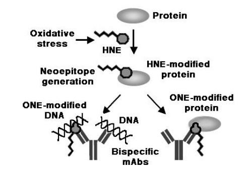
Akagawa M, Ito S, Toyoda K, et al. (2006) Bispecific Abs against modified protein and DNA with oxidized lipids. Proc Natl Acad Sci USA 103: 6160-6165. doi: 10.1073/pnas.0600865103
    [170] Toyoda K, Nagae R, Akagawa M, et al. (2007) Protein-bound 4-hydroxy-2-nonenal. An endogenous triggering antigen of anti-DNA response. J Biol Chem 282: 25769-25778.
    [171] Al-Shobaili HA, Al Robaee AA, Alzolibani AA, et al. (2012) Antibodies against 4-hydroxy-2-nonenal modified epitopes recognized chromatin and its oxidized forms: role of chromatin, oxidized forms of chromatin and 4-hydroxy-2-nonenal modified epitopes on the etiopathogenesis of SLE. Disease Markers 33: 19-34. doi: 10.1155/2012/532497
    [172] Seki S, Kitada T, Yamada T, et al. (2002) In situ detection of lipid peroxidation and oxidative DNA damage in non-alcoholic fatty liver disease. J Hepatol 37: 56-62. doi: 10.1016/S0168-8278(02)00073-9
    [173] Chalasani N, Deeg MA, Crabb DW (2004) Systemic lipid peroxidation and its metabolic and dietary correlates in patients with non-alcoholic steatohepatitis. Am J Gastroenterol 99: 1497-1502. doi: 10.1111/j.1572-0241.2004.30159.x
    [174] Nobili V, Parola M, Alisi A, et al. (2010) Oxidative stress parameters in paediatric non-alcoholic fatty liver disease. Int J Molec Med 26: 471-476.
    [175] Teufel U, Peccerella T, Engelmann G, et al. (2015) Detection of carcinogenic etheno-DNA adducts in children and adolescents with non-alcoholic steatohepatitis (NASH). Hepatobiliary Surg Nutr 4: 426-35.
    [176] Ogawa M, Matsuda T, Ogata A, et al. (2013) DNA damage in rheumatoid arthritis: an age-dependent increase in the lipid peroxidation-derived DNA adduct, heptanone-etheno-2'-deoxycytidine. Autoimmune Dis 2013: 183487.
    [177] Wang G, Pierangeli SS, Papalardo E, et al. (2010) Markers of oxidative and nitrosative stress in systemic lupus erythematosus: correlation with disease activity. Arthritis Rheum 62: 2064-2072.
  • Reader Comments
  • © 2017 the Author(s), licensee AIMS Press. This is an open access article distributed under the terms of the Creative Commons Attribution License (http://creativecommons.org/licenses/by/4.0)
通讯作者: 陈斌, bchen63@163.com
  • 1. 

    沈阳化工大学材料科学与工程学院 沈阳 110142

  1. 本站搜索
  2. 百度学术搜索
  3. 万方数据库搜索
  4. CNKI搜索

Metrics

Article views(11661) PDF downloads(1928) Cited by(139)

Figures and Tables

Figures(10)  /  Tables(1)

/

DownLoad:  Full-Size Img  PowerPoint
Return
Return

Catalog