Citation: Norbert O. Temajo, Neville Howard. The divergence between the virus and cellular oxidative stress as separate environmental agents that trigger autoimmunity originates from their different procedural mechanisms of activating the same molecular entity: the transcription factor NF-kappa B[J]. AIMS Allergy and Immunology, 2017, 1(2): 50-61. doi: 10.3934/Allergy.2017.2.50

| [1] | Ray S, Sonthalia N, Kundu S, et al. (2012) Autoimmune disorders: an overview of molecular and cellular basis in today's perspective. J Clin Cell Immunol S10: 003. |
| [2] |
Von Muhlen CA, Tan EM (1995) Autoantibodies in the diagnosis of systemic rheumatic diseases. Semin Arthritis Rheum 24: 323–358. doi: 10.1016/S0049-0172(95)80004-2

|
| [3] | Temajo NO, Howard N (2014) The virus-induced HSPs regulate the apoptosis of operatus APCs that results in autoimmunity, not in homeostasis. Autoimmun Rev 60: 208–218. |
| [4] |
Temajo NO, Howard N (2012) The viral enterprises in autoimmunity: conversion of target cells into de novo APCs is the presage to autoimmunity. Autoimmun Rev 11: 653–658. doi: 10.1016/j.autrev.2011.11.008
|
| [5] |
Temajo NO, Howard N (2014) The mosaic of environment involvement in autoimmunity: The abrogation of viral latency by stress, a non-infectious environmental agent, is an intrinsic prerequisite prelude before viruses can rank as infectious environmental agents that trigger autoimmune diseases. Autoimmun Rev 13: 635–640. doi: 10.1016/j.autrev.2013.12.003
|
| [6] | Agmon-Levin N, Paz Z, Israeli E, et al. (2009) Vaccines and autoimmunity. Nat Rev Rheumatol 5: 648–652. |
| [7] | Grossman C, Dovrish Z, Shoenfeld Y, et al. (2010) Do infections facilitate the emergence of systemic sclerosis? Autoimmun Rev 10: 244–247. |
| [8] |
Richer MJ, Horwitz MS (2009) Coxackievirus infection as environmental factor in the etiology of type 1 diabetes. Autoimmun Rev 8: 611–615. doi: 10.1016/j.autrev.2009.02.006
|
| [9] |
Goldberg E, Krause I (2009) Infection and type 1 diabetes mellitus-a two edged sword? Autoimmun Rev 8: 682–686. doi: 10.1016/j.autrev.2009.02.017
|
| [10] |
Sansonno L, Tucci FA, Sansonno S, et al. (2009) B cells and HCV: an infection model of autoimmunity. Autoimmun Rev 9: 93–94. doi: 10.1016/j.autrev.2009.03.008
|
| [11] |
Aota N, Shiohara T (2009) Viral connection between drug rashes and autoimmune diseases: how autoimmune responses are generated after resolution of drug rashes. Autoimmun Rev 8: 488–494. doi: 10.1016/j.autrev.2009.02.029
|
| [12] |
Plot L, Amital H (2009) Infectious association of celiac disease. Autoimmun Rev 8: 316–319. doi: 10.1016/j.autrev.2008.10.001
|
| [13] | Rigopoulou EI, Smyk DS, Matthews CE, et al. (2012) Epstein-barr virus as a trigger of autoimmune liver diseases. Adv Virol 2012: 1–12. |
| [14] |
Toussirot E, Roudier J (2008) Epstein-barr virus in autoimmune diseases. Best Pract Res Clin Rheumatol 22: 883–896. doi: 10.1016/j.berh.2008.09.007
|
| [15] |
Alarconriquelme ME (2007) Recent advances in the genetics of autoimmune diseases. Ann N Y Acad Sci 1110: 1–9. doi: 10.1196/annals.1423.001
|
| [16] | Zhu M, Ruddy M, Fu YX (2009) The role of NF-ΚB in central tolerance, In: Moncef Z, The Epigenetics of Autoimmune Diseases, John Wiley & Sons, Ltd, 39–53. |
| [17] | Hoffmann A, Baltimore D (2006) Circuitry of nuclear factor kappa B signaling. Immunol Rev 210: 171–181. |
| [18] | Jacobs MD, Harrison SC (1998) Structure of an IΚBalpha/NF-ΚB complex. Cell 95: 749–758. |
| [19] | Li N, Karin M (1999) Is NF-ΚB the sensor of oxidative stress? FASEB J 13: 1137–1143. |
| [20] |
Hayden MS, Ghosh S (2008) Shared principles in NF-ΚB signalling. Cell 132: 344–362. doi: 10.1016/j.cell.2008.01.020
|
| [21] | Huxford T, Ghosh G (2009) A structural guide to proteins of the NF-ΚB signaling module. CSH Perspect Biol 1: a000075. |
| [22] | Schieber M, Chandel NS (2014) ROS function in redox signaling and oxidative stress. Curr Biol 24: R453–462. |
| [23] |
Morgan MJ, Liu ZG (2011) Crosstalk of reactive oxygen species and NF-ΚB signalling. Cell Res 21: 103–115. doi: 10.1038/cr.2010.178
|
| [24] |
Korn SH, Wouters EF, Vos N, et al. (2001) Cytokine-induced activation of nuclear factor-kappaB is inhibited by hydrogen peroxide through oxidative inactivation of IkappaB kinase. J Biol Chem 276: 35693–35700. doi: 10.1074/jbc.M104321200
|
| [25] | Takada Y, Mukhopadhyay A, Kundu GC, et al. (2003) Hydrogen peroxide activates NF-kappaB through tyrosine phosphorylationof I kappa B alpha and serine phosphorylation of p65: evidence for the involvement of I kappa B alpha kinase and Syk protein-tyrosine kinase. J Biol Chem 278: 24233–24241. |
| [26] | Schieven GL, Kirihara JM, Myers DE, et al. (1993) Reactive oxygen intermediates activate NF-kappa B in a tyrosine kinase-dependent mechanism and in combination with vanadate activate the p56lck and p59fyn tyrosine kinases in human lymphocytes. Blood 82: 1212–1220. |
| [27] |
Jr CT, Jr BE, Farr A, et al. (1999) Oxidative stress induces NF-kappa B nuclear translocation without degradation of IkappaBalpha. Circulation 100: II361–364. doi: 10.1161/01.CIR.100.4.361
|
| [28] | Ferreira V, Schoonbroodt S, Best-Belpomme M, et al. (2000) Crucial role of the amino-terminal tyrosine residue 42 and the carboxyl-terminal PEST domain of I kappa B alpha in NF-kappa B activation by an oxidative stress. J Immun 164: 4292–4300. |
| [29] |
Volanti C, Matroule JY, Piette J (2002) Involvment of oxidative stress in NF-kappaB activation in endothelial cells treated by photodynamic therapy. Photochem Photobiol 75: 36–45. doi: 10.1562/0031-8655(2002)075<0036:IOOSIN>2.0.CO;2
|
| [30] |
Beraud C, Henzel WJ, Baeuerle PA (1999) Involvement of regulatory and catalytic subunits of phosphoinositide 3-kinase in NF-kappaB actvation. P Natl Acad Sci USA 96: 429–434. doi: 10.1073/pnas.96.2.429
|
| [31] |
Fan C, Li Q, Ross D, et al. (2003) Tyrosine phosphorylation of I kappa B activates NF kappa B through a redox-regulated and c-Src-dependent mechanism following hypoxia/reoxygenation. J Biol Chem 278: 2072–2080. doi: 10.1074/jbc.M206718200
|
| [32] |
Lluis JM, Buricchi F, Chiarugi P, et al. (2007) Dual role of mitochondrial reactive oxygen species in hypoxia signalling: activation of nuclear factor- {kappa} B via c-SRC and oxidant-dependent cell death. Cancer Res 67: 7368–7377. doi: 10.1158/0008-5472.CAN-07-0515
|
| [33] |
He Z, Zhao J, Zhang J, et al. (2014) NF-ΚB activation coordinated by IKΚBeta and IKKcephalon enables latent infection of Kaposi's Sarcoma-associated Herpesvirus. J Virol 88: 444–455. doi: 10.1128/JVI.01716-13
|
| [34] |
Zhong H, Voll RE, Ghosh S (1998) Phosphorylation of NF-kappa B p65 by PKA stimulates transcriptional activity by promoting a novel bivalent interaction with the coactivator CBP/p300. Mol Cell 1: 661–671. doi: 10.1016/S1097-2765(00)80066-0
|
| [35] |
Neumann M, Naumann M (2007) Beyond Ikappa Bs: alternative regulation of NF-ΚB activity. FASEB J 21: 2642–2654. doi: 10.1096/fj.06-7615rev
|
| [36] |
Huang B, Yang XD, Lamb A, et al. (2010) Posttranslational modifications of NF-ΚB: another layer of regulation for NF-ΚB signalling pathway. Cell Signal 22: 1282–1290. doi: 10.1016/j.cellsig.2010.03.017
|
| [37] |
Chen LF, Williams SA, Mu Y, et al. (2005) NF-ΚB RelA phosphorylation regulates RelA acetylation. Mol Cell Biol 25: 7966–7975. doi: 10.1128/MCB.25.18.7966-7975.2005
|
| [38] | Hiscott J, Kwon H, Genin P (2001) Hostile takeovers: viral appropriation of the NF-ΚB pathway. J Clin Invest 107: 143–151. |
| [39] |
Zhou FC, Zhang YJ, Deng JH, et al. (2002) Efficient infection by a recombinant Kaposi's sarcoma-associated herpesvirus cloned in a bacterial artificial chromosome: application for genetic analysis. J Virol 76: 6185–6196. doi: 10.1128/JVI.76.12.6185-6196.2002
|
| [40] |
Speck SH, Ganem D (2010) Viral latency and its regulation: lessons from the gamma-herpesviruses. Cell Host Microbe 8: 100–115. doi: 10.1016/j.chom.2010.06.014
|
| [41] |
Lu F, Weidmer A, Liu CG, et al. (2008) Epstein-barr virus-induced MiR-155 attenuates NF-ΚB signaling and stabilizes latent virus persistence. J Virol 82: 10436–10443. doi: 10.1128/JVI.00752-08
|
| [42] | Cullen BR (2006) Viruses and microRNAs. Nat Genet 38 (Suppl): S25–30. |
| [43] | Grey F, Hook L, Nelson J (2007) The functions of herpesvirus-encoded microRNAs. Med Micribiol Immun 197: 261–267. |
| [44] |
Pfeffer S, Voinnet O (2006) Viruses, microRNAs and cancer. Oncogene 25: 6211–6219. doi: 10.1038/sj.onc.1209915
|
| [45] | Kincaid RP, Sullivan CS (2012) Virus-encoded microRNAs: an overview and a look to the future. PLoS Pathog 8: e1003018. |
| [46] |
Murphy E, Vanicek J, Robins H, et al. (2008) Suppression of immediate-early viral gene expression by herpesvirus-coded microRNAs: implications for latency. P Natl Acad Sci USA 105: 5453–5458. doi: 10.1073/pnas.0711910105
|
| [47] |
Pfeffer S, Zavolan M, Grasser FA, et al. (2004) Identification of virus-encoded microRNAs. Science 304:734–736. doi: 10.1126/science.1096781
|
| [48] |
Grey F, Meyers H, White EA, et al. (2007) A human cytomegalovirus-encoded microRNA regulates expression of multiple viral genes involved in replication. PLoS Pathog 3: e163. doi: 10.1371/journal.ppat.0030163
|
| [49] |
Lu F, Stedman W, Yousef M, et al. (2010) Epigenetic regulation of Kaposi's sarcoma-associated herpesvirus latency by virus-encoded microRNAs that target RTA and the cellular Rb12-DNMT pathway. J Virol 84: 2697–2706. doi: 10.1128/JVI.01997-09
|
| [50] |
Bellare P, Ganem D (2009) Regulation of KSHV lytic switch protein expression by virus-encoded microRNA: an evolutionary adaptation that fine-tunes lytic reactivation. Cell Host Microbe 6: 570–575. doi: 10.1016/j.chom.2009.11.008
|
| [51] |
Lin X, Liang D, He Z, et al. (2011) miR-K12-7-5p encoded by Kaposi's sarcoma-associated herpesvirus stabilizes the latent state by targeting viral ORF50/RTA. PLoS One 6: e16224. doi: 10.1371/journal.pone.0016224
|
| [52] |
Bartel DP (2009) MicroRNAs: target recognition and regulatory functions. Cell 136: 215–233. doi: 10.1016/j.cell.2009.01.002
|
| [53] |
Lei X, Bai Z, Ye F, et al. (2010) Regulation of NF-ΚB inhibitor IkappaBalpha and viral replication by a KSHV microRNA. Nat Cell Biol 12:193–199. doi: 10.1038/ncb2019
|
| [54] |
Israel BF, Kenney SC (2003) Virally targeted therapies for EBV-associated malignancies. Oncogene 22: 5122–5130. doi: 10.1038/sj.onc.1206548
|
| [55] |
Pantry SN, Medveczky PG (2009) Epigenetic regulation of Kaposi's sarcoma-associated herpesvirus replication. Semin Cancer Biol 19:153–157. doi: 10.1016/j.semcancer.2009.02.010
|
| [56] | Jens M, Rajewsky N (2014) Competition between target sites of regulators shapes post-transcriptional gene regulation. Nat Rev Genet 16: 113–126. |
| [57] | Karreth FA, Tay Y, Pandolfi PP (2014) Target competition: transcription factors enter the limelight. Genome Biol 15:114–116. |
| [58] |
Brewster RC, Weinert FM, Garcia HG, et al. (2014) The transcription factor titration effect dictates level of gene expression. Cell 156: 1312–1323. doi: 10.1016/j.cell.2014.02.022
|
| [59] |
Lal A, Mazan-Mamczarz K, Kawai T, et al. (2004) Concurrent versus individual binding of HuR and AUF1 to common labile target mRNAs. EMBO J 23: 3092–3102. doi: 10.1038/sj.emboj.7600305
|
| [60] |
Barker A, Epis MR, Porter CJ, et al. (2012) Sequence requirements for RNA binding by HuR and AUF1. J Biochem 151: 423–437. doi: 10.1093/jb/mvs010
|
| [61] |
Martinez NJ, Walhout AJM (2009) The interplay between transcription factors and microRNAs in genome-scale regulatory networks. Bioessays 31: 435–445. doi: 10.1002/bies.200800212
|
| [62] |
Yeger-Loetem E, Sattath S, Kashtan N, et al. (2004) Network motifs in integrated cellular networks of transcription-regulation and protein-protein interaction. P Natl Acad Sci USA 101: 5934–5939. doi: 10.1073/pnas.0306752101
|
| [63] |
Vento-Tormo R, Rodriguez-Ubreva J, Lisio LD, et al. (2014) NF-ΚB directly mediates epigenetic deregulation of common microRNAs in Epstein-Barr virus-mediated transformation of B-cells and in lymphomas. Nucleic Acids Res 42: 11025–11039. doi: 10.1093/nar/gku826
|
| [64] |
Vallabhapurapu S, Karin M (2009) Regulation and function of NF-kappaB transcription factors in the immune system. Annu Rev Immunol 27: 693–733. doi: 10.1146/annurev.immunol.021908.132641
|
| [65] | Temajo NO, Howard N (2014) The virus-induced HSPs regulate the apoptosis of operatus APCs that results in autoimmunity, not in homeostasis. Autoimmun Rev 60: 208–218. |
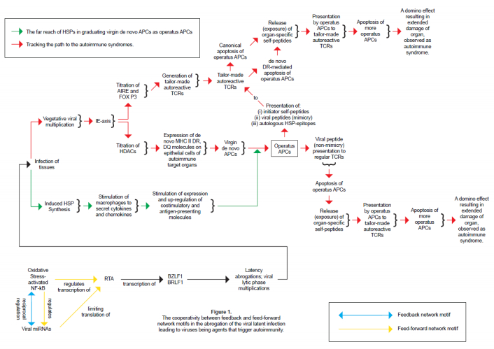
Figures(1) / Tables(1)

Norbert O. Temajo, Neville Howard. The divergence between the virus and cellular oxidative stress as separate environmental agents that trigger autoimmunity originates from their different procedural mechanisms of activating the same molecular entity: the transcription factor NF-kappa B[J]. AIMS Allergy and Immunology, 2017, 1(2): 50-61. doi: 10.3934/Allergy.2017.2.50


 DownLoad: