Electroluminescent (EL) and negative electroluminescent (NEL) devices are radiative thermoelectric energy converters that use electric power for refrigeration. For the EL system, we apply a forward bias to the emitter that we want to cool, whereas a reverse bias voltage is applied to the hot absorber for the NEL system. In this work, we derive the thermodynamic limits of the cooling power density and coefficient of performance (COP) of near-field EL and NEL refrigeration systems based on entropy analysis that considers near-field effects. We show numerically that operating the EL and NEL systems in the near-field regime could increase the cooling power density and the COP bounds to a certain extent. As the vacuum gap decrease from 1000 to 10 nm, the near-field effects improve the performance of the NEL system all the time, but the performance of the EL system increases to the optimal value and then decreases. In addition, the increase in temperature difference weakens the performance of both refrigeration systems greatly. Moreover, we also investigate the effects of the absence of sub-bandgap thermal radiation on the performance of the EL and NEL systems. Our work indicates significant opportunities for evaluating the performance of near-field radiative thermoelectric energy converters from the perspective of thermodynamic limits. Meanwhile, these results establish the targets for cooling power density and COP of the near-field EL and NEL systems.
Citation: Bowen Li, Qiang Cheng, Jinlin Song, Kun Zhou, Lu Lu, Zixue Luo. Thermodynamic performance of near-field electroluminescence and negative electroluminescent refrigeration systems[J]. AIMS Energy, 2021, 9(3): 465-482. doi: 10.3934/energy.2021023
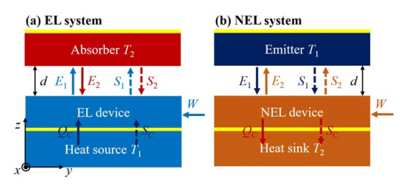
Electroluminescent (EL) and negative electroluminescent (NEL) devices are radiative thermoelectric energy converters that use electric power for refrigeration. For the EL system, we apply a forward bias to the emitter that we want to cool, whereas a reverse bias voltage is applied to the hot absorber for the NEL system. In this work, we derive the thermodynamic limits of the cooling power density and coefficient of performance (COP) of near-field EL and NEL refrigeration systems based on entropy analysis that considers near-field effects. We show numerically that operating the EL and NEL systems in the near-field regime could increase the cooling power density and the COP bounds to a certain extent. As the vacuum gap decrease from 1000 to 10 nm, the near-field effects improve the performance of the NEL system all the time, but the performance of the EL system increases to the optimal value and then decreases. In addition, the increase in temperature difference weakens the performance of both refrigeration systems greatly. Moreover, we also investigate the effects of the absence of sub-bandgap thermal radiation on the performance of the EL and NEL systems. Our work indicates significant opportunities for evaluating the performance of near-field radiative thermoelectric energy converters from the perspective of thermodynamic limits. Meanwhile, these results establish the targets for cooling power density and COP of the near-field EL and NEL systems.

| [1] |
Polder D, Van Hove M (1971) Theory of Radiative Heat Transfer between Closely Spaced Bodies. Phys Rev B 4: 3303-3314. doi: 10.1103/PhysRevB.4.3303

|
| [2] |
Loomis JJ, Maris HJ (1994) Theory of heat transfer by evanescent electromagnetic waves. Phys Rev B 50: 18517-18524. doi: 10.1103/PhysRevB.50.18517
|
| [3] |
Pendry JB (1999) Radiative exchange of heat between nanostructures. J Phys-Condens Mat 11: 6621-6633. doi: 10.1088/0953-8984/11/35/301
|
| [4] |
Fu CJ, Zhang ZM (2006) Nanoscale radiation heat transfer for silicon at different doping levels. Int J Heat Mass Tran 49: 1703-1718. doi: 10.1016/j.ijheatmasstransfer.2005.09.037
|
| [5] |
Volokitin AI, Persson BNJ (2007) Near-field radiative heat transfer and noncontact friction. Rev Mod Phys 79: 1291-1329. doi: 10.1103/RevModPhys.79.1291
|
| [6] |
Hu L, Narayanaswamy A, Chen X, et al. (2008) Near-field thermal radiation between two closely spaced glass plates exceeding Planck's blackbody radiation law. Appl Phys Lett 92: 133106. doi: 10.1063/1.2905286
|
| [7] |
Basu S, Zhang ZM, Fu CJ (2009) Review of near-field thermal radiation and its application to energy conversion. Int J Energ Res 33: 1203-1232. doi: 10.1002/er.1607
|
| [8] |
Rousseau E, Siria A, Jourdan G, et al. (2009) Radiative heat transfer at the nanoscale. Nat Photonics 3: 514-517. doi: 10.1038/nphoton.2009.144
|
| [9] |
Shen S, Narayanaswamy A, Chen G (2009) Surface Phonon Polaritons Mediated Energy Transfer between Nanoscale Gaps. Nano Lett 9: 2909-2913. doi: 10.1021/nl901208v
|
| [10] |
Qu W, Mudawar I (2002) Experimental and numerical study of pressure drop and heat transfer in a single-phase micro-channel heat sink. Int J Heat Mass Tran 45: 2549-2565. doi: 10.1016/S0017-9310(01)00337-4
|
| [11] |
Kittel A, Muller-Hirsch W, Parisi J, et al. (2005) Near-field heat transfer in a scanning thermal microscope. Phys Rev Lett 95: 224301. doi: 10.1103/PhysRevLett.95.224301
|
| [12] |
Ottens RS, Quetschke V, Wise S, et al. (2011) Near-field radiative heat transfer between macroscopic planar surfaces. Phys Rev Lett 107: 014301. doi: 10.1103/PhysRevLett.107.014301
|
| [13] |
St-Gelais R, Guha B, Zhu L, et al. (2014) Demonstration of strong near-field radiative heat transfer between integrated nanostructures. Nano Lett 14: 6971-6975. doi: 10.1021/nl503236k
|
| [14] |
Song B, Fiorino A, Meyhofer E, et al. (2015) Near-field radiative thermal transport: From theory to experiment. Aip Adv 5: 053503. doi: 10.1063/1.4919048
|
| [15] |
Laroche M, Carminati R, Greffet JJ (2006) Near-field thermophotovoltaic energy conversion. J Appl Phys 100: 063704. doi: 10.1063/1.2234560
|
| [16] |
Svetovoy VB, Palasantzas G (2014) Graphene-on-Silicon near-field thermophotovoltaic cell. Phys Rev Appl 2: 034006 doi: 10.1103/PhysRevApplied.2.034006
|
| [17] |
Chang JY, Yang Y, Wang LP (2015) Tungsten nanowire based hyperbolic metamaterial emitters for near-field thermophotovoltaic applications. Int J Heat Mass Tran 87: 237-247. doi: 10.1016/j.ijheatmasstransfer.2015.03.087
|
| [18] |
Lenert A, Bierman DM, Nam Y, et al. (2014) A nanophotonic solar thermophotovoltaic device. Nat Nanotechnol 9: 126-130. doi: 10.1038/nnano.2013.286
|
| [19] |
Fiorino A, Zhu L, Thompson D, et al. (2018) Nanogap near-field thermophotovoltaics. Nat Nanotechnol 13: 806-811. doi: 10.1038/s41565-018-0172-5
|
| [20] |
Lin C, Wang B, Teo KH, et al. (2017) Near-field enhancement of thermoradiative devices. J Appl Phys 122: 143102. doi: 10.1063/1.5007036
|
| [21] |
Wang B, Lin C, Teo KH, et al. (2017) Thermoradiative device enhanced by near-field coupled structures. J. Quant Spectros Radiat Transfer 196: 10-16. doi: 10.1016/j.jqsrt.2017.03.038
|
| [22] |
Liao T, Zhang X, Yang Z, et al. (2019) Near-Field Thermoradiative Electron Device. IEEE Trans Electron Devices 66: 3099-3102. doi: 10.1109/TED.2019.2915765
|
| [23] |
Chen K, Santhanam P, Sandhu S, et al. (2015) Heat-flux control and solid-state cooling by regulating chemical potential of photons in near-field electromagnetic heat transfer. Phys Rev B 91: 134301. doi: 10.1103/PhysRevB.91.134301
|
| [24] |
Liu X, Zhang ZM (2016) High-performance electroluminescent refrigeration enabled by photon tunneling. Nano Energy 26: 353-359. doi: 10.1016/j.nanoen.2016.05.049
|
| [25] |
Liao T, Tao C, Chen X, et al. (2019) Parametric optimum design of a near-field electroluminescent refrigerator. J Phys D: Appl Phys 52: 325108. doi: 10.1088/1361-6463/ab2341
|
| [26] |
Chen K, Santhanam P, Fan S (2016) Near-Field enhanced negative luminescent refrigeration. Phys Rev Appl 6: 024014. doi: 10.1103/PhysRevApplied.6.024014
|
| [27] |
Lin C, Wang B, Teo KH, et al. (2018) A coherent description of thermal radiative devices and its application on the near-field negative electroluminescent cooling. Energy 147: 177-186. doi: 10.1016/j.energy.2018.01.005
|
| [28] |
Zhou C, Zhang Y, Qu L, et al. (2020) Near-field negative electroluminescent cooling via nanoparticle doping. J Quant Spectrosc Radiat Transfer 245: 106889-106897. doi: 10.1016/j.jqsrt.2020.106889
|
| [29] |
Wurfel P (1982) The chemical potential of radiation. J Phys C Solid State Phys 15: 3967. doi: 10.1088/0022-3719/15/18/012
|
| [30] |
Tervo E, Bagherisereshki E, Zhang Z (2017) Near-field radiative thermoelectric energy converters: a review. Front Energy 12: 5-21. doi: 10.1007/s11708-017-0517-z
|
| [31] | Tauc J (1957) The share of thermal energy taken from the surroundings in the electro-luminescent energy radiated from a p-n junction. Cechoslovackij Fiziceskij Zurnal 7: 275-276. |
| [32] | Dousmanis G, Mueller C, Nelson H, et al. (1964) Evidence of refrigerating action by means of photon emission in semiconductor diodes. Phys Rev 133: A316-A318. |
| [33] |
Berdahl P (1985) Radiant refrigeration by semiconductor diodes. J Appl Phys 58: 1369-1374. doi: 10.1063/1.336309
|
| [34] |
Mal'Shukov A, Chao K (2001) Opto-thermionic refrigeration in semiconductor heterostructures. Phys Rev Lett 86: 5570. doi: 10.1103/PhysRevLett.86.5570
|
| [35] |
Han P, Jin KJ, Zhou YL, et al. (2006) Analysis of optothermionic refrigeration based on semiconductor heterojunction. J Appl Phys 99: 074504. doi: 10.1063/1.2188249
|
| [36] |
Yen ST, Lee KC (2010) Analysis of heterostructures for electroluminescent refrigeration and light emitting without heat generation. J Appl Phys 107: 054513. doi: 10.1063/1.3326944
|
| [37] |
Oksanen J, Tulkki J (2010) Thermophotonic heat pump—a theoretical model and numerical simulations. J Appl Phys 107: 093106. doi: 10.1063/1.3419716
|
| [38] | Santhanam P, Huang D, Gray Jr DJ, et al. (2013) Electro-luminescent cooling: light emitting diodes above unity efficiency. Laser Refrigeration of Solids VI, 863807. |
| [39] |
Santhanam P, Gray DJ Jr, Ram RJ (2012) Thermoelectrically pumped light-emitting diodes operating above unity efficiency. Phys Rev Lett 108: 097403. doi: 10.1103/PhysRevLett.108.097403
|
| [40] |
Guha B, Otey C, Poitras CB, et al. (2012) Near-field radiative cooling of nanostructures. Nano Lett 12: 4546-4550. doi: 10.1021/nl301708e
|
| [41] |
Bewley WW, Jurkovic MJ, Felix CL, et al. (2001) HgCdTe photodetectors with negative luminescent efficiencies > 80%. Appl Phys Lett 78: 3082-3084. doi: 10.1063/1.1370539
|
| [42] |
Nash GR, Ashby MK, Lindle JR, et al. (2003) Long wavelength infrared negative luminescent devices with strong Auger suppression. J Appl Phys 94: 7300-7304. doi: 10.1063/1.1625094
|
| [43] |
Ashley T, Gordon NT, Nash GR, et al. (2001) Long-wavelength HgCdTe negative luminescent devices. Appl Phys Lett 79: 1136-1138. doi: 10.1063/1.1395521
|
| [44] |
Hoffman D, Hood A, Wei Y, et al. (2005) Negative luminescence of long-wavelength InAs∕GaSb superlattice photodiodes. Appl Phys Lett 87: 201103. doi: 10.1063/1.2130536
|
| [45] |
Ashley T, Elliott CT, Gordon NT, et al. (1995) Negative luminescence from In1−xAlxSb and CdxHg1−xTe diodes. Infrared Phys Technol 36: 1037-1044. doi: 10.1016/1350-4495(95)00043-7
|
| [46] |
Zhu L, Fiorino A, Thompson D, et al. (2019) Near-field photonic cooling through control of the chemical potential of photons. Nature 566: 239-244. doi: 10.1038/s41586-019-0918-8
|
| [47] |
Rawat R, Lamba R, Kaushik SC (2017) Thermodynamic study of solar photovoltaic energy conversion: An overview. Renewable Sustainable Energy Rev 71: 630-638. doi: 10.1016/j.rser.2016.12.089
|
| [48] |
Ruan XL, Rand SC, Kaviany M (2007) Entropy and efficiency in laser cooling of solids. Phys Rev B 75: 214304. doi: 10.1103/PhysRevB.75.214304
|
| [49] |
Hsu WC, Tong JK, Liao B, et al. (2016) Entropic and near-field improvements of thermoradiative cells. Sci Rep 6: 34837. doi: 10.1038/srep34837
|
| [50] |
Gribik J, Osterle J (1984) The second law efficiency of solar energy conversion. J Sol Energy Eng 106: 16-21. doi: 10.1115/1.3267555
|
| [51] |
Pusch A, Gordon JM, Mellor A, et al. (2019) Fundamental efficiency bounds for the conversion of a radiative heat engine's own emission into work. Phys Rev Appl 12: 064018. doi: 10.1103/PhysRevApplied.12.064018
|
| [52] |
Li W, Buddhiraju S, Fan S (2020) Thermodynamic limits for simultaneous energy harvesting from the hot sun and cold outer space. Light Sci Appl 9: 68. doi: 10.1038/s41377-020-0296-x
|
| [53] |
Dorofeyev I (2011) Thermodynamic functions of fluctuating electromagnetic fields within a heterogeneous system. Phys Scr 84: 055003. doi: 10.1088/0031-8949/84/05/055003
|
| [54] |
Perez-Madrid A, Lapas LC, Rubi JM (2009) Heat exchange between two interacting nanoparticles beyond the fluctuation-dissipation regime. Phys Rev Lett 103: 048301. doi: 10.1103/PhysRevLett.103.048301
|
| [55] |
Pérez-Madrid A, Rubí JM, Lapas LC (2008) Heat transfer between nanoparticles: Thermal conductance for near-field interactions. Phys Rev B 77: 155417 doi: 10.1103/PhysRevB.77.155417
|
| [56] |
Latella I, Pérez-Madrid A, Lapas LC, et al. (2014) Near-field thermodynamics: Useful work, efficiency, and energy harvesting. J Appl Phys 115: 124307. doi: 10.1063/1.4869744
|
| [57] |
Narayanaswamy A, Zheng Y (2013) Theory of thermal nonequilibrium entropy in near-field thermal radiation. Phys Rev B 88: 075412. doi: 10.1103/PhysRevB.88.075412
|
| [58] |
Li B, Cheng Q, Song J, et al. (2020) Evaluation of performance of near-field thermophotovoltaic systems based on entropy analysis. J Appl Phys 127: 063103. doi: 10.1063/1.5135729
|
| [59] |
Ravindra NM, Srivastava VK (1979) Temperature dependence of the energy gap in semiconductors. J Phys Chem Solids 40: 791-793. doi: 10.1016/0022-3697(79)90162-8
|
| [60] | Palik ED (1985) Handbook of Optical Constants of Solids, Orlando: Academic Press. |
| [61] |
Johnson PB, Christy RW (1972) Optical Constants of the Noble Metals. Phys Rev B 6: 4370-4379. doi: 10.1103/PhysRevB.6.4370
|
| [62] |
Kruger M, Emig T, Kardar M (2011) Nonequilibrium electromagnetic fluctuations: heat transfer and interactions. Phys Rev Lett 106: 210404. doi: 10.1103/PhysRevLett.106.210404
|
| [63] |
Otey C, Fan S (2011) Numerically exact calculation of electromagnetic heat transfer between a dielectric sphere and plate. Phys Rev B 84: 245431. doi: 10.1103/PhysRevB.84.245431
|
| [64] | Chew WC (1995) Waves and Fields in Inhomogeneous Media, New York: IEEE. |
| [65] |
Basu S, Lee BJ, Zhang ZM (2010) Infrared radiative properties of heavily doped silicon at room temperature. J Heat Transfer 132: 023301. doi: 10.1115/1.4000171
|
| [66] |
Smith GB (1990) Theory of angular selective transmittance in oblique columnar thin films containing metal and voids. Appl Opt 29: 3685-3693. doi: 10.1364/AO.29.003685
|
| [67] | Zhang Z (2007) Nano/microscale heat transfer, New York: McGraw-Hill. |


Figures(11)

Bowen Li, Qiang Cheng, Jinlin Song, Kun Zhou, Lu Lu, Zixue Luo. Thermodynamic performance of near-field electroluminescence and negative electroluminescent refrigeration systems[J]. AIMS Energy, 2021, 9(3): 465-482. doi: 10.3934/energy.2021023


 DownLoad: