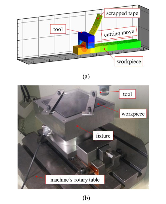
In this work, a novel method for a more sustainable recycling and cost-efficient manufacturing technique of polyether ketone ketone (PEKK) based thermoplastic composite materials is proposed to recover and reprocess waste and end-of-life materials in the aerospace industry. For the recycling of carbon fiber reinforced thermoplastics (CFrTP), an innovative scrapping process based on mechanical cutting was developed and the properties of the obtained scrap and the recycled panel were analyzed. Thus, a cutting tool was developed for the delamination of the input material so that long fibers can be retained in the resulting scrap. Different processing approaches of material scrapping were evaluated, aiming to obtain manageable scrap that can be subsequently used for a compression molding process. Additionally, an automatic process was evaluated to manage the scrap and perform the corresponding lay-up to manufacture high-quality thermoplastic composite products with recycled materials.
Citation: Alejandro Sandá, Rocío Ruiz, Miguel Ángel Mafé, Jon Ander Sarasua, Antonio González-Jiménez. Scrapping of PEKK-based thermoplastic composites retaining long fibers and their use for compression molded recycled parts[J]. AIMS Materials Science, 2023, 10(5): 819-834. doi: 10.3934/matersci.2023044
In this work, a novel method for a more sustainable recycling and cost-efficient manufacturing technique of polyether ketone ketone (PEKK) based thermoplastic composite materials is proposed to recover and reprocess waste and end-of-life materials in the aerospace industry. For the recycling of carbon fiber reinforced thermoplastics (CFrTP), an innovative scrapping process based on mechanical cutting was developed and the properties of the obtained scrap and the recycled panel were analyzed. Thus, a cutting tool was developed for the delamination of the input material so that long fibers can be retained in the resulting scrap. Different processing approaches of material scrapping were evaluated, aiming to obtain manageable scrap that can be subsequently used for a compression molding process. Additionally, an automatic process was evaluated to manage the scrap and perform the corresponding lay-up to manufacture high-quality thermoplastic composite products with recycled materials.

| [1] |
Fontaine P, Weiss-Hortala E, Botaro V, et al. (2021) Impact of atmosphere on recovered carbon fibers from poly ether ether ketone (PEEK) based composites during thermoconversion. Waste Biomass Valor 12: 6389–6402. https://doi.org/10.1007/s12649-021-01445-7 doi: 10.1007/s12649-021-01445-7

|
| [2] |
Borjan D, Knez Ž, Knez M (2021) Recycling of carbon fibre-reinforced composites—difficulties and future perspectives. Materials 12: 4191–4204. https://doi.org/10.3390/ma14154191 doi: 10.3390/ma14154191
|
| [3] | Directive 2008/98/EC of the European Parliament and of the Council of 19 November 2008 on waste and repealing certain Directives. Available from: http://data.europa.eu/eli/dir/2008/98/2018-07-05. |
| [4] | Chawla KK (2012) Composite Materials Science and Engineering, 3Eds., New York: Springer New York. |
| [5] |
Howarth J, Mareddy SSR, Mativenga PT (2014) Energy intensity and environmental analysis of mechanical recycling of carbon fibre composite. J Clean Prod 81: 46–50. https://doi.org/10.1016/j.jclepro.2014.06.023 doi: 10.1016/j.jclepro.2014.06.023
|
| [6] | Pickering SJ, Yip H, Kennerley JR, et al. (2000) The recycling of carbon fibre composites using a fluidised bed process, In: Gibson AG, FRC 2000–Composites for the Millennium, Cambridge: Woodhead Publishing. |
| [7] |
Lam KL, Oyedun AO, Cheung KY, et al. (2011) Modelling pyrolysis with dynamic heating. Chem Eng Sci 66: 6505–6514. https://doi.org/10.1016/j.ces.2011.09.013 doi: 10.1016/j.ces.2011.09.013
|
| [8] | Oliveux G, Dandy L, Leeke GA (2014) A step change in the recycling of composite materials. 16th European Conference on Composite Materials, ECCM 2014, 2–5. |
| [9] |
Yang Y, Boom R, Irion B, et al. (2012) Recycling of composite materials. Chem Eng Process 51: 53–68. https://doi.org/10.1016/j.cep.2011.09.007 doi: 10.1016/j.cep.2011.09.007
|
| [10] |
Li X, Bai R, McKechnie J (2016) Environmental and financial performance of mechanical recycling of carbon fibre reinforced polymers and comparison with conventional disposal routes. J Clean Prod 127: 451–460. https://doi.org/10.1016/j.jclepro.2016.03.139 doi: 10.1016/j.jclepro.2016.03.139
|
| [11] |
Vincent GA (2019) Recycling of thermoplastic composite laminates: The role of processing. University of Twente. https://doi.org/10.3990/1.9789036548526 doi: 10.3990/1.9789036548526
|
| [12] |
Vincent GA, de Bruijn TA, Wijskamp S, et al. (2019) Shredding and sieving thermoplastic composite scrap: Method development and analyses of the fibre length distributions. Compos Part B-Eng 176: 107197. https://doi.org/10.1016/j.compositesb.2019.107197 doi: 10.1016/j.compositesb.2019.107197
|
| [13] |
Li H, Englund K (2017) Recycling of carbon fibre-reinforced thermoplastic composite wastes from the aerospace industry. J Compos Mater 51: 1265–1273. https://doi.org/10.1177/0021998316671796 doi: 10.1177/0021998316671796
|
| [14] |
Roux M, Eguémann N, Dransfeld C, et al. (2017) Thermoplastic carbon fibre-reinforced polymer recycling with electrodynamical fragmentation: From cradle to cradle. J Thermoplast Compos 30: 381–403. https://doi.org/10.1177/0892705715599431 doi: 10.1177/0892705715599431
|
| [15] |
Li H, Qin X, He G, et al. (2016) Investigation of chip formation and fracture toughness in orthogonal cutting of UD-CFRP. Int J Adv Manuf Technol 82: 1079–1088. https://doi.org/10.1007/s00170-015-7471-x doi: 10.1007/s00170-015-7471-x
|
| [16] |
An Q, Cai C, Cai X, et al. (2019) Experimental investigation on the cutting mechanism and surface generation in orthogonal cutting of UD-CFRP laminates. Compos Struct 230: 111441. https://doi.org/10.1016/j.compstruct.2019.111441 doi: 10.1016/j.compstruct.2019.111441
|
| [17] |
Herzog D, Schmidt-Lehr M, Oberlander M, et al. (2016) Laser cutting of carbon fibre reinforced plastics of high thickness. Mater Design 92: 742–749. https://doi.org/10.1016/j.matdes.2015.12.056 doi: 10.1016/j.matdes.2015.12.056
|
| [18] |
MM IW, Azmi A, Lee C, et al. (2018) Kerf taper and delamination damage minimization of FRP hybrid composites under abrasive water-jet machining. Int J Adv Manuf Technol 94: 1727–1744. https://doi.org/10.1007/s00170-016-9669-y doi: 10.1007/s00170-016-9669-y
|
| [19] | de Bruijn TA, Vincent GA, van Hattum F (2017) Recycling C/PPS laminates into long fibre thermoplastic composites by low shear mixing. 21st International Conference on Composite Materials 2017, 20–25. Available from: http://www.iccm-central.org/Proceedings/ICCM21proceedings/papers/4122.pdf. |
| [20] |
Vincent GA, de Bruijn TA, Wijskamp S, et al. (2021) Characterisation and improvement of the quality of mixing of recycled thermoplastic composites. Compos Part C-Open 4: 100108. https://doi.org/10.1016/j.jcomc.2021.100108 doi: 10.1016/j.jcomc.2021.100108
|
| [21] |
Feraboli P, Cleveland T, Ciccu M, et al. (2010) Defect and damage analysis of advanced discontinuous carbon/epoxy composite materials. Compos Part A-Appl S 41: 888–901. https://doi.org/10.1016/j.compositesa.2010.03.002 doi: 10.1016/j.compositesa.2010.03.002
|
| [22] |
Landry B, Hubert P (2015) Experimental study of defect formation during processing of randomly-oriented strand carbon/PEEK composites. Compos Part A-Appl S 77: 301–309. https://doi.org/10.1016/j.compositesa.2015.05.020 doi: 10.1016/j.compositesa.2015.05.020
|
 matersci-10-05-044-Supplementary.pdf matersci-10-05-044-Supplementary.pdf |
 |


Figures(5) / Tables(5)

Alejandro Sandá, Rocío Ruiz, Miguel Ángel Mafé, Jon Ander Sarasua, Antonio González-Jiménez. Scrapping of PEKK-based thermoplastic composites retaining long fibers and their use for compression molded recycled parts[J]. AIMS Materials Science, 2023, 10(5): 819-834. doi: 10.3934/matersci.2023044


 DownLoad: