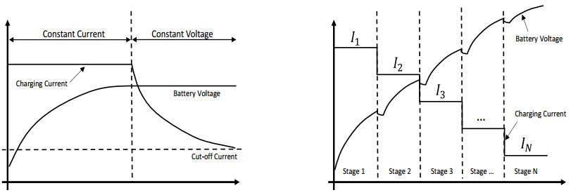
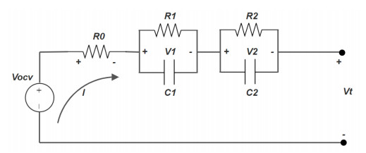
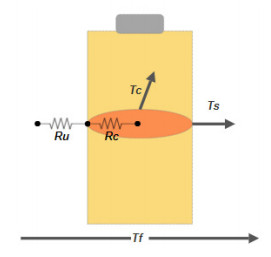
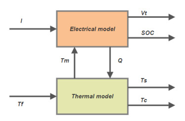
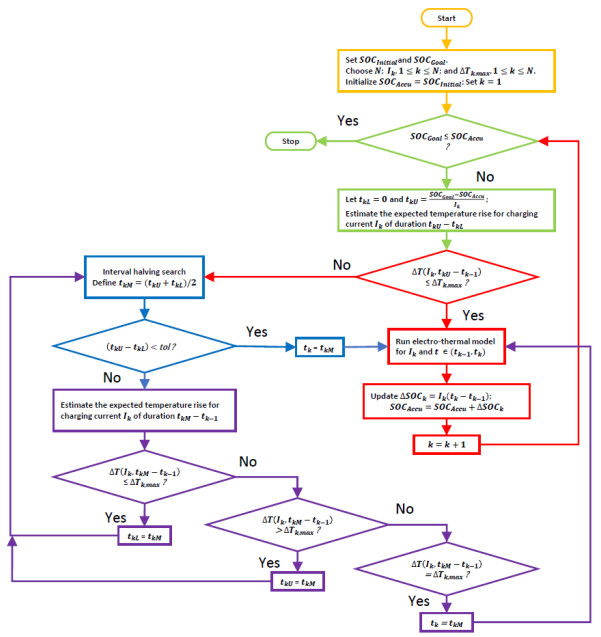
This paper utilizes an integrated electro-thermal model of a lithium-ion battery to search for an optimal multistage constant current charge pattern that will minimize the total charging time of the battery, while restricting its temperature rise in each stage within safe limits. The model consists of two interlinked components, an electrical equivalent circuit model to continuously predict the battery's terminal voltage and a thermal model to continuously predict its temperature rise as charging progresses. The proposed optimization algorithm is based on a novel stepwise single-variable search technique that is very easy to implement and converges quickly. The results of our extensive simulation studies clearly indicate that the proposed charging strategy offers a fast, safe and easy-to-implement alternative to many of the existing computationally intensive optimal charging strategies.
Citation: Saad Jarid, Manohar Das. An Electro-Thermal Model based fast optimal charging strategy for Li-ion batteries[J]. AIMS Energy, 2021, 9(5): 915-933. doi: 10.3934/energy.2021043
This paper utilizes an integrated electro-thermal model of a lithium-ion battery to search for an optimal multistage constant current charge pattern that will minimize the total charging time of the battery, while restricting its temperature rise in each stage within safe limits. The model consists of two interlinked components, an electrical equivalent circuit model to continuously predict the battery's terminal voltage and a thermal model to continuously predict its temperature rise as charging progresses. The proposed optimization algorithm is based on a novel stepwise single-variable search technique that is very easy to implement and converges quickly. The results of our extensive simulation studies clearly indicate that the proposed charging strategy offers a fast, safe and easy-to-implement alternative to many of the existing computationally intensive optimal charging strategies.

| [1] | Burch I, Gilchrist J (2018) Survey of Global Activity to Phase Out Internal Combustion Engine Vehicles. Center of Climate Protection: Santa Rosa, CA, USA. |
| [2] |
Deng D (2015) Li-ion batteries: basics, progress, and challenges. Energy Sci Eng 3: 385-418. doi: 10.1002/ese3.95

|
| [3] |
Liu K, Zou C, Li K (2018) Charging pattern optimization for lithium-ion batteries with an electrothermal-aging model. IEEE Trans Ind Inf 14: 5463-5474. doi: 10.1109/TII.2018.2866493
|
| [4] |
Zhao J, Liao L, Shi F, et al. (2017) Surface fluorination of reactive battery anode materials for enhanced stability. J Am Chem Soc 139: 11550-11558. doi: 10.1021/jacs.7b05251
|
| [5] |
Dong J, Liu C, Lin Z (2014) Charging infrastructure planning for promoting battery electric vehicles: An activity-based approach using multiday travel data. Transp Res Part C Emerg Technol 38: 44-55. doi: 10.1016/j.trc.2013.11.001
|
| [6] |
Leng F, Tan C, Pecht M (2015) Effect of temperature on the aging rate of Li Ion battery operating above room temperature. Sci Rep 5: 12967. doi: 10.1038/srep12967
|
| [7] |
Cheng K, Divakar B, Wu H, et al. (2011) Battery-Management System (BMS) and SOC development for electrical vehicles. IEEE Trans Veh Technol 60: 76-88. doi: 10.1109/TVT.2010.2089647
|
| [8] |
Saidani F, Hutter F, Scurtu R, et al. (2017) Lithium-ion battery models: A comparative study and a model-based powerline communication. Adv Radio Sci 15: 83-91. doi: 10.5194/ars-15-83-2017
|
| [9] |
Zhang C, Jiang J, Gao Y, et al. (2017) Charging optimization in lithium-ion batteries based on temperature rise and charge time. Appl Energy 194: 569-577. doi: 10.1016/j.apenergy.2016.10.059
|
| [10] |
Yanga X, Zhang G, Ge S, et al. (2018) Fast charging of lithium-ion batteries at all temperatures. Proc National Acad Sci 115: 7266-7271. doi: 10.1073/pnas.1807115115
|
| [11] |
Kim K, Lee Y, Kang K, et al. (2012) A simple method for solving the voltage overshoots of LiFePO4-based lithium-ion batteries with different capacity classes. RSC Adv 2: 3844-3849. doi: 10.1039/c2ra20273e
|
| [12] |
Jiang J, Zhang C, Wen J, et al. (2013) An optimal charging method for Li-ion batteries using a fuzzy-control approach based on polarization properties. IEEE Trans Veh Technol 62: 3000-3009. doi: 10.1109/TVT.2013.2252214
|
| [13] |
Choi S, Lim H (2002) Factors that affect cycle-life and possible degradation mechanisms of a Li-ion cell based on LiCoO2. J Power Sources 111: 130-136. doi: 10.1016/S0378-7753(02)00305-1
|
| [14] |
Guo Z, Liaw B, Qiu X, et al. (2015) Optimal charging method for lithium-ion batteries using a universal voltage protocol accommodating aging. J Power Sources 274: 957-964. doi: 10.1016/j.jpowsour.2014.10.185
|
| [15] |
Vo T, Chen X, Shen W, et al. (2015) New charging strategy for lithium-ion batteries based on the integration of Taguchi method and state of charge estimation. J Power Sources 273: 413-422. doi: 10.1016/j.jpowsour.2014.09.108
|
| [16] |
Chen G, Liu Y, Wang S, et al. (2021) Searching for the optimal current pattern based on grey wolf optimizer and equivalent circuit model of Li-ion batteries. J Energy Storage 33: 101933. doi: 10.1016/j.est.2020.101933
|
| [17] |
Jiang L, Li Y, Ma J, et al. (2020) Hybrid charging strategy with adaptive current control of Lithium-ion battery for electric vehicles. Renewable Energy 160: 1385-1395. doi: 10.1016/j.renene.2020.07.018
|
| [18] | Liu J, Li G, Fathy K (2016) A computationally efficient approach for optimizing lithium-ion battery charging. J Dyn Syst Meas Control 138: 1009-1-1009-8. |
| [19] |
Xu M, Wang R, Zhao P, et al. (2019) Fast charging optimization for lithium-ion batteries based on dynamic programming algorithm and electrochemical-thermal-capacity fade coupled model. J Power Sources 438: 227015. doi: 10.1016/j.jpowsour.2019.227015
|
| [20] |
Liu C, Gao Y, Liu L (2021) Toward safe and rapid battery charging: Design optimal fast charging strategies thorough a physics-based model considering lithium plating. Int J Energy Res 45: 2303-2320. doi: 10.1002/er.5924
|
| [21] |
Hu X, Li S, Peng H, et al. (2013) Charging time and loss optimization for LiNMC and LiFePO4 batteries based on equivalent circuit models. J Power Sources 239: 449-457. doi: 10.1016/j.jpowsour.2013.03.157
|
| [22] |
Zhang S, Zhang C, Xiong R, et al. (2014) Study on the optimal charging strategy for lithium-ion batteries used in electric vehicles. Energies 7: 6783-6797. doi: 10.3390/en7106783
|
| [23] |
Lin X, Perez H, Mohan S, et al. (2014) A lumped-parameter electro-thermal model for cylindrical batteries. J Power Sources 257: 1-11. doi: 10.1016/j.jpowsour.2014.01.097
|
| [24] |
Forgez C, Do D, Friedrich G, et al. (2010) Thermal modeling of a cylindrical LiFePO4/graphite lithium-ion battery. J Power Sources 195: 2961-2968. doi: 10.1016/j.jpowsour.2009.10.105
|
| [25] | Luo Y, Liu Y, Wang S (2009) Search for an optimal multistage charging pattern for lithium-ion batteries using the Taguchi approach. Tencon 2009 IEEE Region 10 Conf: 1-5. |
| [26] |
Lu B, Zhao Y, Song Y, et al. (2018) Stress limited fast charging methods with time varying current in lithium-ion batteries. Electrochim Acta 288: 144-152. doi: 10.1016/j.electacta.2018.09.009
|
| [27] |
Novais S, Nascimento M, Grande L, et al. (2016) Internal and external temperature monitoring of a Li-ion battery with fiber Bragg grating sensors. Sensors 16: 1394. doi: 10.3390/s16091394
|
| [28] |
Chen M, Mora G (2006) Accurate electrical battery model capable of predicting runtime and I-V performance. IEEE Trans Energy Convers 21: 504-511. doi: 10.1109/TEC.2006.874229
|
| [29] |
Zhang X, Kong X, Li G, et al. (2014) Thermodynamic assessment of active cooling/heating methods for lithium-ion batteries of electric vehicles in extreme conditions. Energy: 64: 1092-1101. doi: 10.1016/j.energy.2013.10.088
|
| [30] |
Zhang R, Xia B, Li B, et al. (2018) A study on the open circuit voltage and state of charge characterization of high capacity lithium-ion battery under different temperature. Energies 11: 2408. doi: 10.3390/en11092408
|
| [31] |
Swiderska-Mocek A, Rudnicka E, Lewandowski A (2019) Temperature coefficients of Li-ion battery single electrode potentials and related entropy changes—revisited. Phys Chem Chem Phys 21: 2115-2120. doi: 10.1039/C8CP06638H
|
| [32] |
Shabani B, Biju M (2015) Theoretical modelling methods for thermal management of batteries. Energies 8: 10153-10177. doi: 10.3390/en80910153
|
| [33] | Rao S (2009) Engineering Optimization: Theory and Practice. 4th Ed, John Wiley and Sons, Hoboken New Jersey. |
| [34] | LithiumWerks 26650 Lithium Ion Power Cell Datasheet. Available from: https://a123batteries.com/product_images/uploaded_images/26650.pdf. |
Figures(9) / Tables(5)

Saad Jarid, Manohar Das. An Electro-Thermal Model based fast optimal charging strategy for Li-ion batteries[J]. AIMS Energy, 2021, 9(5): 915-933. doi: 10.3934/energy.2021043


 DownLoad: