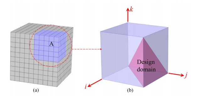
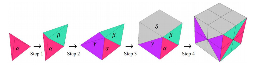
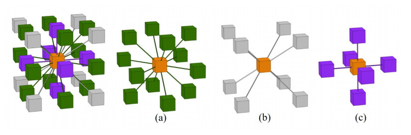
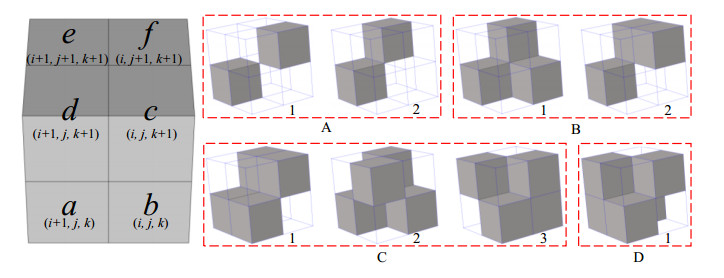
Phononic crystals (PnCs) possessing desired bandgaps find many potential applications for elastic wave manipulation. Considering the propagating essence of three-dimensional (3D) elastic waves and the interface influence of multiphase material, the bandgap design of 3D single-phase PnCs is crucial and appealing. Currently, the main approaches for designing 3D single-phase PnCs rely on less efficient trial-and-error approaches, which are heavily dependent on researchers' empirical knowledge. In comparison, topology optimization offers a dominant advantage by transcending the restriction of predefined microstructures and obtaining topologies with desired performance. This work targeted the exploration of various novel microstructures with exceptional performance by geometric-constrained topology optimization. To deal with high-dimensional design variables in topology optimization, the unit cell structure of a PnC was confined by pyramid symmetry to maximumly deduct the variable number of the unit cell. More importantly, to alleviate mesh dependence inherent in conventional topology optimization, node-to-node and edge-to-edge connection strategies were adopted, supplemented by the insertion of cylinders to ensure the stability of these connections. Finally, unstable PnC structures were filtered out using extra geometric constraints. Leveraging the proposed framework for the optimization of 3D single-phase PnCs, various novel structures were obtained. Particularly, our results demonstrate that PnC structures with only one type of mass lump exhibit significant potential to possess outstanding performance, and geometric configurations of the ultimately optimized structures are intricately linked to the particular sequence of the bandgaps.
Citation: Cheng Xiong, Yi Xiao, Qing-Hua Qin, Hui Wang, Zhuo-Ran Zeng. Bandgap design of 3D single-phase phononic crystals by geometric-constrained topology optimization[J]. AIMS Materials Science, 2024, 11(3): 415-437. doi: 10.3934/matersci.2024021
Phononic crystals (PnCs) possessing desired bandgaps find many potential applications for elastic wave manipulation. Considering the propagating essence of three-dimensional (3D) elastic waves and the interface influence of multiphase material, the bandgap design of 3D single-phase PnCs is crucial and appealing. Currently, the main approaches for designing 3D single-phase PnCs rely on less efficient trial-and-error approaches, which are heavily dependent on researchers' empirical knowledge. In comparison, topology optimization offers a dominant advantage by transcending the restriction of predefined microstructures and obtaining topologies with desired performance. This work targeted the exploration of various novel microstructures with exceptional performance by geometric-constrained topology optimization. To deal with high-dimensional design variables in topology optimization, the unit cell structure of a PnC was confined by pyramid symmetry to maximumly deduct the variable number of the unit cell. More importantly, to alleviate mesh dependence inherent in conventional topology optimization, node-to-node and edge-to-edge connection strategies were adopted, supplemented by the insertion of cylinders to ensure the stability of these connections. Finally, unstable PnC structures were filtered out using extra geometric constraints. Leveraging the proposed framework for the optimization of 3D single-phase PnCs, various novel structures were obtained. Particularly, our results demonstrate that PnC structures with only one type of mass lump exhibit significant potential to possess outstanding performance, and geometric configurations of the ultimately optimized structures are intricately linked to the particular sequence of the bandgaps.

| [1] |
Kushwaha MS, Halevi P, Martínez G, et al. (1994) Theory of acoustic band structure of periodic elastic composites. Phys Rev B 49: 2313. https://doi.org/10.1103/PhysRevB.49.2313 doi: 10.1103/PhysRevB.49.2313

|
| [2] |
Khelif A, Choujaa A, Benchabane S, et al. (2004) Guiding and bending of acoustic waves in highly confined phononic crystal waveguides. Appl Phys Lett 84: 4400–4402. https://doi.org/10.1063/1.1757642 doi: 10.1063/1.1757642
|
| [3] |
Song A, Chen T, Wang X, et al. (2016) Tunable broadband unidirectional acoustic transmission based on a waveguide with phononic crystal. Appl Phys A 122: 1–7. https://doi.org/10.1007/s00339-016-0295-1 doi: 10.1007/s00339-016-0295-1
|
| [4] |
Lee J, Kim Y (2009) Topology optimization of muffler internal partitions for improving acoustical attenuation performance. Int J Numer Meth Eng 80: 455–477. https://doi.org/10.1002/nme.2645 doi: 10.1002/nme.2645
|
| [5] |
Li X, Ni X, Feng L, et al. (2011) Tunable unidirectional sound propagation through a sonic-crystal-based acoustic diode. Phys Rev Lett 106: 084301. https://doi.org/10.1103/PhysRevLett.106.084301 doi: 10.1103/PhysRevLett.106.084301
|
| [6] |
Pennec Y, Djafari-Rouhani B, Vasseur J, et al. (2004) Tunable filtering and demultiplexing in phononic crystals with hollow cylinders. Phys Rev E 69: 046608. https://doi.org/10.1103/PhysRevE.69.046608 doi: 10.1103/PhysRevE.69.046608
|
| [7] |
Qiu C, Liu Z, Shi J, et al. (2005) Mode-selecting acoustic filter by using resonant tunneling of two-dimensional double phononic crystals. Appl Phys Lett 87: 104101. https://doi.org/10.1063/1.2037853 doi: 10.1063/1.2037853
|
| [8] |
Hussein M, Hamza K, Hulbert G, et al. (2006) Multiobjective evolutionary optimization of periodic layered materials for desired wave dispersion characteristics. Struct Multidiscip O 31: 60–75. https://doi.org/10.1007/s00158-005-0555-8 doi: 10.1007/s00158-005-0555-8
|
| [9] |
Bacigalupo A, Lepidi M (2018) Acoustic wave polarization and energy flow in periodic beam lattice materials. Int J Solids Struct 147: 183–203. https://doi.org/10.1016/j.ijsolstr.2018.05.025 doi: 10.1016/j.ijsolstr.2018.05.025
|
| [10] |
Zhang Z, Li Y, Meng F, et al. (2017) Topological design of phononic band gap crystals with sixfold symmetric hexagonal lattice. Comp Mater Sci 139: 97–105. https://doi.org/10.1016/j.commatsci.2017.07.037 doi: 10.1016/j.commatsci.2017.07.037
|
| [11] |
Wang K, Liu Y, Wang B (2019) Ultrawide band gap design of phononic crystals based on topological optimization. Physica B 571: 263–272. https://doi.org/10.1016/j.physb.2019.07.012 doi: 10.1016/j.physb.2019.07.012
|
| [12] |
Cheng Q, Guo H, Yuan T, et al. (2020) Topological design of square lattice structure for broad and multiple band gaps in the low-frequency range. Extreme Mech Lett 35: 100632. https://doi.org/10.1016/j.eml.2020.100632 doi: 10.1016/j.eml.2020.100632
|
| [13] |
Hedayatrasa S, Kersemans M, Abhary K, et al. (2018) Optimization and experimental validation of stiff porous phononic plates for widest complete bandgap of mixed fundamental guided wave modes. Mech Syst Signal Pr 98: 786–801. https://doi.org/10.1016/j.ymssp.2017.05.019 doi: 10.1016/j.ymssp.2017.05.019
|
| [14] |
Xu W, Ning J, Lin Z, et al. (2020) Multi-objective topology optimization of two-dimensional multi-phase microstructure phononic crystals. Mater Today Commun 22: 100801. https://doi.org/10.1016/j.mtcomm.2019.100801 doi: 10.1016/j.mtcomm.2019.100801
|
| [15] |
Chen Y, Meng F, Sun G, et al. (2017) Topological design of phononic crystals for unidirectional acoustic transmission. J Sound Vib 410: 103–123. https://doi.org/10.1016/j.jsv.2017.08.015 doi: 10.1016/j.jsv.2017.08.015
|
| [16] |
Xiong C, Lee C, Qin Q (2023) Topology optimization of single-phase phononic crystals based on a search-space-reduction strategy with a Genetic Algorithm. Mater Today Commun 34: 105069. https://doi.org/10.1016/j.mtcomm.2022.105069 doi: 10.1016/j.mtcomm.2022.105069
|
| [17] |
Zhang M, Hu C, Yin C, et al. (2021) Design of elastic metamaterials with ultra-wide low-frequency stopbands via quantitative local resonance analysis. Thin Wall Struct 165: 107969. https://doi.org/10.1016/j.tws.2021.107969 doi: 10.1016/j.tws.2021.107969
|
| [18] |
D'Alessandro L, Belloni E, Ardito R, et al. (2017) Mechanical low-frequency filter via modes separation in 3D periodic structures. Appl Phys Lett 111: 231902. https://doi.org/10.1063/1.4995554 doi: 10.1063/1.4995554
|
| [19] |
Delpero T, Schoenwald S, Zemp A, et al. (2016) Structural engineering of three-dimensional phononic crystals. J Sound Vib 363: 156–165. https://doi.org/10.1016/j.jsv.2015.10.033 doi: 10.1016/j.jsv.2015.10.033
|
| [20] |
Elmadih W, Chronopoulos D, Syam W, et al. (2019) Three-dimensional resonating metamaterials for low-frequency vibration attenuation. Sci Rep 9: 11503. https://doi.org/10.1038/s41598-019-47644-0 doi: 10.1038/s41598-019-47644-0
|
| [21] |
McGee O, Jiang H, Qian F, et al. (2019) 3D printed architected hollow sphere foams with low-frequency phononic band gaps. Addit Manuf 30: 100842. https://doi.org/10.1016/j.addma.2019.100842 doi: 10.1016/j.addma.2019.100842
|
| [22] |
Zhang X, Ye H, Wei N, et al. (2021) Design optimization of multifunctional metamaterials with tunable thermal expansion and phononic bandgap. Mater Design 209: 109990. https://doi.org/10.1016/j.matdes.2021.109990 doi: 10.1016/j.matdes.2021.109990
|
| [23] |
Dong J, Qin Q, Xiao Y (2020) Nelder–mead optimization of elastic metamaterials via machine-learning-aided surrogate modeling. Int J Appl Mech 12: 2050011. https://doi.org/10.1142/S1758825120500118 doi: 10.1142/S1758825120500118
|
| [24] |
D'Alessandro L, Bahr B, Daniel L, et al. (2017) Shape optimization of solid–air porous phononic crystal slabs with widest full 3D bandgap for in-plane acoustic waves. J Comput Phys 344: 465–484. https://doi.org/10.1016/j.jcp.2017.05.018 doi: 10.1016/j.jcp.2017.05.018
|
| [25] |
Jiang H, Chen Y (2019) Lightweight architected hollow sphere foams for simultaneous noise and vibration control. J Phys D Appl Phys 52: 325303. https://doi.org/10.1088/1361-6463/ab22ee doi: 10.1088/1361-6463/ab22ee
|
| [26] |
D'Alessandro L, Belloni E, Ardito R, et al. (2016) Modeling and experimental verification of an ultra-wide bandgap in 3D phononic crystal. Appl Phys Lett 109: 221907. https://doi.org/10.1063/1.4971290 doi: 10.1063/1.4971290
|
| [27] |
D'Alessandro L, Ardito R, Braghin F, et al. (2019) Low frequency 3D ultra-wide vibration attenuation via elastic metamaterial. Sci Rep 9: 8039. https://doi.org/10.1038/s41598-019-44507-6 doi: 10.1038/s41598-019-44507-6
|
| [28] |
Muhammad (2021) Design and manufacturing of monolithic mechanical metastructures governing ultrawide low frequency three-dimensional bandgaps. Addit Manuf 47: 47. https://doi.org/10.1016/J.ADDMA.2021.102231 doi: 10.1016/J.ADDMA.2021.102231
|
| [29] |
Gazzola C, Caverni S, Corigliano A (2021) From mechanics to acoustics: Critical assessment of a robust metamaterial for acoustic insulation application. Appl Acoust 183: 108311. https://doi.org/10.1016/j.apacoust.2021.108311 doi: 10.1016/j.apacoust.2021.108311
|
| [30] |
Aravantinos-Zafiris N, Lucklum F, Sigalas M (2021) Complete phononic band gaps in the 3D Yablonovite structure with spheres. Ultrasonics 110: 106265. https://doi.org/10.1016/j.ultras.2020.106265 doi: 10.1016/j.ultras.2020.106265
|
| [31] |
Fei X, Jin L, Zhang X, et al. (2020) Three-dimensional anti-chiral auxetic metamaterial with tunable phononic bandgap. Appl Phys Lett 116: 021902. https://doi.org/10.1063/1.5132589 doi: 10.1063/1.5132589
|
| [32] |
Lu Y, Yang Y, Guest J, et al. (2017) 3-D phononic crystals with ultra-wide band gaps. Sci Rep 7: 43407. https://doi.org/10.1038/srep43407 doi: 10.1038/srep43407
|
| [33] |
Gao H, Qu Y, Meng G (2023) Topology optimization and wave propagation of three-dimensional phononic crystals. J Vib Acoust 145: 011002. https://doi.org/10.1115/1.4054745 doi: 10.1115/1.4054745
|
| [34] |
Wu K, Otoo E, Suzuki K (2009) Optimizing two-pass connected-component labeling algorithms. Pattern Anal Applic 12: 117–135. https://doi.org/10.1007/s10044-008-0109-y doi: 10.1007/s10044-008-0109-y
|
| [35] |
He L, Chao Y, Suzuki K (2008) A run-based two-scan labeling algorithm. IEEE T Image Process 17: 749–756. https://doi.org/10.1109/TIP.2008.919369 doi: 10.1109/TIP.2008.919369
|
| [36] |
Xia X (2012) Particle swarm optimization method based on chaotic local search and roulette wheel mechanism. Phys Procedia 24: 269–275. https://doi.org/10.1016/j.phpro.2012.02.040 doi: 10.1016/j.phpro.2012.02.040
|
| [37] |
D'Alessandro L, Zega V, Ardito R, et al. (2018) 3D auxetic single material periodic structure with ultra-wide tunable bandgap. Sci Rep 8: 2262. https://doi.org/10.1038/s41598-018-19963-1 doi: 10.1038/s41598-018-19963-1
|
Figures(14)

Cheng Xiong, Yi Xiao, Qing-Hua Qin, Hui Wang, Zhuo-Ran Zeng. Bandgap design of 3D single-phase phononic crystals by geometric-constrained topology optimization[J]. AIMS Materials Science, 2024, 11(3): 415-437. doi: 10.3934/matersci.2024021


 DownLoad: