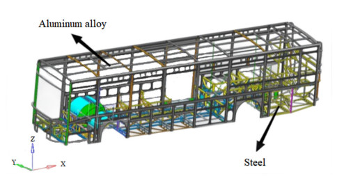
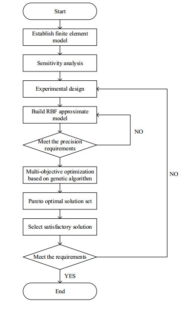
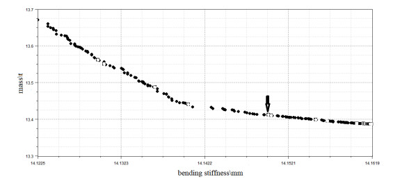
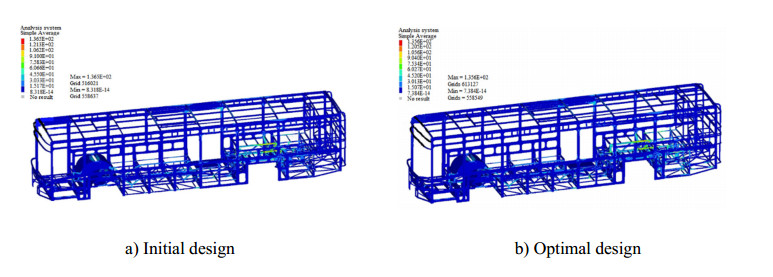
In order to solve the problem of insufficient range caused by the excessive weight of the pure electric bus, a multi-objective genetic algorithm (GA) and radial basis function (RBF) model are combined in this paper to realize the lightweighting of steel and aluminum hybrid body of the pure electric bus. First, the upper and lower frames of the pure electric bus body are initially designed with aluminum alloy and steel materials respectively to meet the lightweight requirements. Second, a finite element (FE) model of the bus body is established, and the validity of the model is validated through physical tests. Then, the sensitivity analysis is performed to identify the relative importance of individual design parameters over the entire domain. The Hamosilei sampling method is selected for the design of the experiment (DOE) because users can specify the number of experiments and ensure that the set of random numbers is a good representative of real variability, and the RBF model is adopted to approximate the responses of objectives and constraints. Finally, the multi-objective optimization (MOO) method based on GA with RBF model is used to solve the optimization problem of the lightweight steel-aluminum hybrid bus body. The results show that compared with the traditional fully steel body, the use of the aluminum alloy lower-frame structure can reduce body mass by 38.4%, and the proposed optimization method can further reduce the mass of the steel-aluminum body to 4.28% without affecting the structural stiffness and strength performance of the body.
Citation: Wuhua Jiang, Yuexin Zhang, Jie Liu, Daisheng Zhang, Yajie Yan, Chuanzheng Song. Multi-objective optimization design for steel-aluminum lightweight body of pure electric bus based on RBF model and genetic algorithm[J]. Electronic Research Archive, 2023, 31(4): 1982-1997. doi: 10.3934/era.2023102
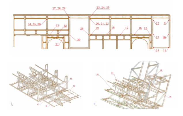
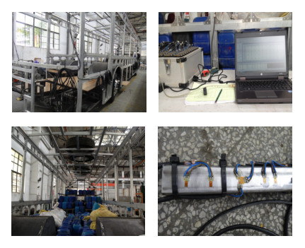
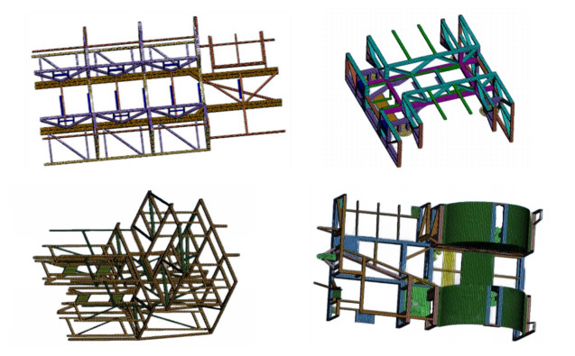
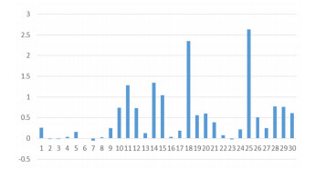
In order to solve the problem of insufficient range caused by the excessive weight of the pure electric bus, a multi-objective genetic algorithm (GA) and radial basis function (RBF) model are combined in this paper to realize the lightweighting of steel and aluminum hybrid body of the pure electric bus. First, the upper and lower frames of the pure electric bus body are initially designed with aluminum alloy and steel materials respectively to meet the lightweight requirements. Second, a finite element (FE) model of the bus body is established, and the validity of the model is validated through physical tests. Then, the sensitivity analysis is performed to identify the relative importance of individual design parameters over the entire domain. The Hamosilei sampling method is selected for the design of the experiment (DOE) because users can specify the number of experiments and ensure that the set of random numbers is a good representative of real variability, and the RBF model is adopted to approximate the responses of objectives and constraints. Finally, the multi-objective optimization (MOO) method based on GA with RBF model is used to solve the optimization problem of the lightweight steel-aluminum hybrid bus body. The results show that compared with the traditional fully steel body, the use of the aluminum alloy lower-frame structure can reduce body mass by 38.4%, and the proposed optimization method can further reduce the mass of the steel-aluminum body to 4.28% without affecting the structural stiffness and strength performance of the body.

| [1] |
L. Yu, X. Gu, L. Qian, P. Jiang, W. Wang, M. Yu, Application of tailor rolled blanks in optimum design of pure electric vehicle crashworthiness and lightweight, Thin-Walled Struct., 161 (2021), 107410. https://doi.org/10.1016/j.tws.2020.107410 doi: 10.1016/j.tws.2020.107410

|
| [2] |
S. Baeka, G. Y. Go, J. W. Park, J. Song, H. Lee, S. J. Lee, et al., Microstructural and interface geometrical influence on the mechanical fatigue property of aluminum/high-strength steel lap joints using resistance element welding for lightweight vehicles: experimental and computational investigation, J. Mater. Res. Technol., 17 (2022), 658–678. https://doi.org/10.1016/j.jmrt.2022.01.041 doi: 10.1016/j.jmrt.2022.01.041
|
| [3] |
S. B. Lu, W. B. Jiang, W. J. Zuo, Size and morphology crashworthiness optimization for automotive frontal structures using equivalent static loads method, J. Vibr. Shock, 37 (2018), 56–61. https://doi.org/10.13465/j.cnki.jvs.2018.07.009 doi: 10.13465/j.cnki.jvs.2018.07.009
|
| [4] |
H. Zhao, S. Wang, X. Li, Z. Pang, G. Zhang, Optimization for side structure of vehicle based on FEA, Procedia Comput. Sci., 208 (2022), 196–205. https://doi.org/10.1016/j.procs.2022.10.029 doi: 10.1016/j.procs.2022.10.029
|
| [5] |
D. Jasoliya, D. B. Shah, A. M. Lakdawala, Topological optimization of wheel assembly components for all terrain vehicles, Mater. Today Proc., 59 (2022), 878–883. https://doi.org/10.1016/j.matpr.2022.01.221 doi: 10.1016/j.matpr.2022.01.221
|
| [6] |
X. Xu, Y. Zhang, X. Wang, J. Fang, J. Chen, J. Li, Searching superior crashworthiness performance by constructing variable thickness honeycombs with biomimetic cells, Int. J. Mech. Sci., 235 (2022), 107718. https://doi.org/10.1016/j.ijmecsci.2022.107718 doi: 10.1016/j.ijmecsci.2022.107718
|
| [7] |
D. Xie, L. Chen, L. Liu, L. Chen, H. Wang, Actuators and sensors for application in agricultural robots: a review, Machines, 10 (2022), 913. https://doi.org/10.3390/machines10100913 doi: 10.3390/machines10100913
|
| [8] | A. Ariyarit, P. Katasila, T. Srinaem, W. Sukkhanthong, The multi-objective design optimization of automated guided vehicles car structure using genetic algorithms, in 2020 IEEE 11th International Conference on Mechanical and Intelligent Manufacturing Technologies (ICMIMT), (2020), 103–107. https: //doi.org/10.1109/ICMIMT49010.2020.9041222 |
| [9] |
Z. Xiang, Z. Zhu, Multi-objective optimization of a composite orthotropic bridge with RSM and NSGA-Ⅱ algorithm, J. Constr. Steel Res., 188 (2022), 106938. https://doi.org/10.1016/j.jcsr.2021.106938 doi: 10.1016/j.jcsr.2021.106938
|
| [10] |
Z. Zhang, X. Jia, T. Yang, Y. Gu, W. Wang, L. Chen, Multi-objective optimization of lubricant volume in an ELSD considering thermal effects, Int. J. Therm. Sci., 164 (2021), 106884. https://doi.org/10.1016/j.ijthermalsci.2021.106884 doi: 10.1016/j.ijthermalsci.2021.106884
|
| [11] |
Y. Ji, Z. Yang, J. Ran, H. Li, Multi-objective parameter optimization of turbine impeller based on RBF neural network and NSGA-Ⅱ genetic algorithm, Energy Rep., 7 (2021), 584–593. https://doi.org/10.1016/j.egyr.2021.10.003 doi: 10.1016/j.egyr.2021.10.003
|
| [12] |
J. Vorderbrüggen, D. Köhler, B. Grüber, J. Troschitz, M. Gude, G. Meschut, Development of a rivet geometry for solid self-piercing riveting of thermally loaded CFRP-metal joints in automotive construction, Compos. Struct., 291 (2022), 115583. https://doi.org/10.1016/j.compstruct.2022.115583 doi: 10.1016/j.compstruct.2022.115583
|
| [13] | P. K. Mallick, Joining for lightweight vehicles, in Materials, Design and Manufacturing for Lightweight Vehicles, (2011), 275–308. https://doi.org/10.1533/9781845697822.2.275 |
| [14] |
Y. Niu, J. Shao, J. Xiao, W. Song, Z. Cao, Multi-objective evolutionary algorithm based on RBF network for solving the stochastic vehicle routing problem, Inf. Sci., 609 (2022), 387–410. https://doi.org/10.1016/j.ins.2022.07.087 doi: 10.1016/j.ins.2022.07.087
|
| [15] |
G. E. Tsekouras, J. Tsimikas, On training RBF neural networks using input–output fuzzy clustering and particle swarm optimization, Fuzzy Sets Syst., 221 (2013), 65–89. https://doi.org/10.1016/j.fss.2012.10.004 doi: 10.1016/j.fss.2012.10.004
|
| [16] |
A. Konak, D. W. Coit, A. E. Smith, Multi-objective optimization using genetic algorithms: a tutorial, Reliab. Eng. Syst. Saf., 91 (2006), 992–1007. https://doi.org/10.1016/j.ress.2005.11.018 doi: 10.1016/j.ress.2005.11.018
|
| [17] |
F. Chi, Y. Xu, Building performance optimization for university dormitory through integration of digital gene map into multi-objective genetic algorithm, Appl. Energy, 307 (2022), 118211. https://doi.org/10.1016/j.apenergy.2021.118211 doi: 10.1016/j.apenergy.2021.118211
|
Figures(13) / Tables(3)
Wuhua Jiang, Yuexin Zhang, Jie Liu, Daisheng Zhang, Yajie Yan, Chuanzheng Song. Multi-objective optimization design for steel-aluminum lightweight body of pure electric bus based on RBF model and genetic algorithm[J]. Electronic Research Archive, 2023, 31(4): 1982-1997. doi: 10.3934/era.2023102


 DownLoad: