Citation: Shafiuzzaman Khan Khadem, Malabika Basu, Michael F. Conlon. Capacity enhancement and flexible operation of unified power quality conditioner in smart and microgrid network[J]. AIMS Energy, 2018, 6(1): 49-69. doi: 10.3934/energy.2018.1.49
[1] | Ahsan Iqbal, Ayesha Ayoub, Asad Waqar, Azhar Ul-Haq, Muhammad Zahid, Syed Haider . Voltage stability enhancement in grid-connected microgrid using enhanced dynamic voltage restorer (EDVR). AIMS Energy, 2021, 9(1): 150-177. doi: 10.3934/energy.2021009 |
[2] | H. H. H. De Silva, D. K. J. S. Jayamaha, N. W. A. Lidula . Review on design and control of solid state transformer based microgrids. AIMS Energy, 2019, 7(6): 901-923. doi: 10.3934/energy.2019.6.901 |
[3] | Mohamed G Moh Almihat . An overview of AC and DC microgrid energy management systems. AIMS Energy, 2023, 11(6): 1031-1069. doi: 10.3934/energy.2023049 |
[4] | Kushan Tharuka Lulbadda, K. T. M. U. Hemapala . The additional functions of smart inverters. AIMS Energy, 2019, 7(6): 971-988. doi: 10.3934/energy.2019.6.971 |
[5] | W. E. P. Sampath Ediriweera, N. W. A. Lidula . Design and protection of microgrid clusters: A comprehensive review. AIMS Energy, 2022, 10(3): 375-411. doi: 10.3934/energy.2022020 |
[6] | W. E. P. Sampath Ediriweera, N. W. A. Lidula, R. Samarasinghe . Ring connected microgrid clusters for improved resiliency in distribution systems with high solar PV penetration. AIMS Energy, 2024, 12(4): 872-904. doi: 10.3934/energy.2024041 |
[7] | HVV Priyadarshana, MA Kalhan Sandaru, KTMU Hemapala, WDAS Wijayapala . A review on Multi-Agent system based energy management systems for micro grids. AIMS Energy, 2019, 7(6): 924-943. doi: 10.3934/energy.2019.6.924 |
[8] | Md Mashud Hyder, Kaushik Mahata . Reconfiguration of distribution system using a binary programming model. AIMS Energy, 2016, 4(3): 461-480. doi: 10.3934/energy.2016.3.461 |
[9] | T S S Senarathna, K T M Udayanga Hemapala . Review of adaptive protection methods for microgrids. AIMS Energy, 2019, 7(5): 557-578. doi: 10.3934/energy.2019.5.557 |
[10] | Konstantinos Christidis, Michael Devetsikiotis . Adaptive multi-tiered resource allocation policy for microgrids. AIMS Energy, 2016, 4(2): 300-312. doi: 10.3934/energy.2016.2.300 |
Integration of uncontrollable distributed generation (DG) sources in different places of the low voltage distribution network increasing the complexity of power quality control and efficient energy management [1,2]. To overcome the power quality problems related to the distributed generation systems in the distribution network, the functionality of custom power devices such as active power filter (APF), dynamic voltage restorer (DVR), unified power quality conditioner (UPQC) in the distribution network are also increasing [3]. In general, APF unit is placed in series (APFse) in the network to control it as a DVR and its functionality deals with the voltage quality improvement. When the APF is placed in parallel (APFsh) it works as static compensator and eliminates the harmonic current of the network. UPQC is the combination of both series and shunt APF units and connected by a common dc link capacitor. Thus its functionality starts from the compensation of voltage and current disturbance [4,5], but extends towards integration with DG to compensate voltage interruption, reactive power management in both interconnected and islanded mode [6]. Recent articles also show the placement and integration of UPQC in the DG connected microgrid (µGrid) network is very effective for both seamless islanding and reconnection process [7,8].
To improve the power quality in high power applications, the filtering task of UPQC cannot be performed for the whole spectrum of harmonics by using a single converter/APFsh unit. It is due to the limitations on switching frequency and power rating of the semiconductor devices. Therefore, the parallel operation of multiple low power APFsh units has evolved as a neutral choices where switching frequency needs not be compromised [9]. These can form a distributed active filter systems (DAFS), as shown in Figure 1a where multiple APFsh units can be installed on the same location or different locations within the power system [10]. The other advantages of distributed/multi-unit parallel APFsh approach are; (ⅰ) operation and control flexibility, (ⅱ) reliability because of redundancy, (ⅲ) easy to increase the capacity when load increases and (ⅳ) user-friendly in terms of maintenance. Research also reported about multiple uninterruptible power supply (UPS) systems located in an interconnected electrical power network, as shown in Figure 1b, to form online/line-interactive distributed UPS (DUPS) system [11]. It is to be noted that, in general the functionality of APFsh and UPS are different. APFsh deals only with voltage/current harmonic compensation in the distribution network whereas UPS is for providing emergency power to the load when the mains power fails or interrupts.
In terms of UPQC, it can provide the combined functionalities of APFsh and UPS. In general UPQC is used for voltage/current harmonic compensation, supply side voltage sag/swell compensation and power factor improvement as well. With the addition of storage in the dc link part, this UPQC can also supply the active power to the load when needed [7]. The multi-level and modular topologies of UPQC are also proposed in [12,13,14,15,16,17,18] to mitigate the PQ problems in medium voltage (MV) and high power level. Review shows that these solutions are suitable for distribution network where both the current and voltage are high [19]. They also have some level of redundancy but in a complex manner. Most of the cases, the control is centralized. Therefore, further capacity expansion may not be possible or easier. Operational flexibility is also not explained. Their integration with DG sources may also be complicated. These configurations may also not be suitable for low voltage distribution lines where the 3-phase voltage (typically 400 VL-L) is low, but the expected compensating current is comparatively high with increased harmonics. In that case, multi-level or modular type series APFse (connected in parallel mode) may not be required. But for high current compensation, multiple APFsh units in a parallel distributed mode should be effective.
On the other hand, like DAFS [10] and DUPS [11], to achieve the distributed condition and control, multiple UPQC units can also be placed at nearby or different locations in the low voltage network. In that circumstances, multiple APFse units connected in series in the same distribution line may not be a right decision. It will also incur additional cost for the system. A single series APFse unit for voltage sag/swell compensation and multiple shunt APFsh units in distributed mode to compensate the reactive power including current and voltage harmonics can be a better solution for power quality improvement in low voltage network. Therefore, authors propose a modified UPQC unit for low voltage distribution network where single APFse and multiple APFsh units can be connected with a common dc linked capacitor and can form a distributed UPQC (D-UPQC), as shown in Figure 1c. In the proposed system, multiple APFsh units are installed on the same location in the distribution line. These issues are discussed and quantified for possible capacity enhancement with operational flexibility.
Based on the capacity/rating and operating condition (amount of sag/swell compensation) of APFse, multiple APFsh units can be switched ON/OFF to compensate the reactive and harmonic power/current either individually/combined according to their capacities which is detailed in section 2. This APFsh units could work in a distributed mode and the ON/OFF switches are controlled by the central controller of D-UPQC in a coordinated manner. The other advantages of D-UPQC can be noted as below:
• Multiple APFsh units can compensate voltage harmonics, reactive current and harmonics (even for different harmonic level) individually or collectively.
• The D-UPQC can maximize its efficiency by choosing the number of units, hence loss can be minimized.
• Ease of placement/integration in single/three phase network with different requirement of compensating current in different phases.
• Easy integration with DG sources either through dc link/at PCC as shown in [6,7].
This paper deals with the following sections. For the proposed D-UPQC, the capacity enhancement limit and the possible operational flexibility have been discussed in the design and control issues. Section 2 and 3 respectively deal with these issues. Section 4 shows the results of a simulation study which is carried out to obtain the performance of the proposed system. The concluding remarks are made in Section 5.
To start with simplicity, Figure 2a shows the working diagram of the proposed D-UPQC where the APFsh units are installed on the same location. Figure 2b shows the equivalent electrical circuit of the system assuming that the reactive part of the load current will be compensated by the APFsh1 and the harmonic part will be equally divided and compensated by the rest of the APFsh units. Here the subscripts f, p, q and h denote the fundamental, active, reactive and harmonic components respectively. Figure 2c shows the tetrahedron diagram of the load current and it also reflects the amount and components of the load current that will be compensated by the APFsh units of the proposed D-UPQC. Thus the source will provide the active fundamental part of the load current in phase with the voltage to maintain the unity power factor at the PCC and the $TH{D_{Ipcc}}$ will be kept within the IEEE standard and specified limit.
The integration of APFsh units as a part of the possible capacity enhancement in the operation of D-UPQC mainly depends on the rating of APFse (or the size of the series transformer) and the operating condition (amount of sag/swell compensation with time). The design issues related to the APFse and APFsh are discussed below.
In general, the full load current flows through the series transformer of the APFse when APFsh is inactive. As the APFsh units compensate the reactive and harmonic part of the load current, the minimum current rating of the APFse (${I_{se}}$) should be equal to the load active fundamental current (${I_{lfp}}$) (1), as shown in Figure 3a. The voltage rating of the APFse (${V_{se}}$) should be equal to the highest value of the injected sag voltage (${V_{sag}}$) (2). If k is the fraction of the supply voltage (${V_s}$) that will appear as a voltage sag, then the required source current (${I_s}$) that will be transferred through the series transformer of the APFse, as shown in Figure 3b, can be calculated as (3). This source current will be the current rating of APFse to compensate the k ($ \le 1$) amount of voltage sag. Therefore:
$ {I_{se,min}} = {I_{lfp}} $ | (1) |
$ {V_{se,rated}} = {V_{sag,max}} = k{V_{l,rated}} $ | (2) |
$ {I_{se}} = I'_s = \frac{1}{{\left( {1 - k} \right)}}{I_{lfp}} $ | (3) |
$ {V_{se}} = k{V_s} $ | (4) |
The current carrying capacity of the series transformer will be:
$ {I_{Tr - se}} = {I_{se}} + {I_{loss}} $ | (5) |
where ${I_{loss}}$ represents the amount of fundamental current that is required to maintain the operation of the UPQC. It is reflected as a ${P_{loss}}$ in the control method. Therefore, this ${I_{Tr -se}}$ will be the maximum rating for the APFse as shown in Figure 3b. It also indicates the maximum limit of the active fundamental component of the load current that can be used in the network followed by the UPQC.
The sag compensation strategy by $I'_s$ can also create an additional VA loading effect on the APFsh control [20]. This can be minimized by introducing a direct link between the DC capacitor and the storage system, as discussed in the integration of UPQC in μGrid (UPQCµG) by the same authors [7].
In stable operating conditions, when no voltage sag appears in the network, the APFsh units compensate the reactive and harmonic parts of the load current. According to Figure 2c, the load current is composed of active, reactive and harmonic components. The source supplies the active load fundamental (${I_s} = {I_{lf}}cos{\theta _{lf}}$) and ${I_{loss}}$ through the series transformer. Both the source and APFse do not deal with the reactive and harmonic part of the load. Therefore, ${I_s}$ and ${I_{se}}$ are not directly related to the selection of maximum current rating of the APFsh (${I_{lfq -max}}$ and ${I_{lh -max}}$). The size of the series transformer actually imposes the limit of maximum ${I_{loss}}$ that can be used for the operation and capacity enhancement of D-UPQC. The possible maximum ${I_{loss}}$ can be found from (5) and considered by the APFsh as:
$ {I_{loss - max}} = {I_{Tr - se}}\;\;{\rm{while}}\;\;{I_{se}} = 0 $ | (6) |
This can be represent as: ${I_{loss}} = \alpha {I_{Tr -se}}$, where $\alpha $ is a fraction of ${I_{Tr -se}}$.
Again, the amount of ${I_{loss}}$ depends on the rating of APF units [21]. This can be related as:
$ {I_{loss}} = \beta {I_{sh}};\;{\rm{while}}\;\;\beta \;\;{\rm{is}}\;{\rm{a}}\;{\rm{fraction}}\;{\rm{of}}\;\;{I_{sh}} $ | (7) |
Therefore, the possible ${I_{sh -max}}$ to integrate in the UPQC system and to compensate the reactive and harmonic components of the load current (${I_{lfq -max}}\; and\; {I_{lh -max}}$), as shown in the Figure 3a can be written as:
$ {I_{sh - max}} = \frac{\alpha }{\beta }{I_{Tr - se}};\;{\rm{while}}\;\;{I_{se}} = 0 $ | (8) |
This rating will decrease when the D-UPQC will have the capacity of voltage sag compensation, as shown in Figure 3b. In that case, the required amount of current for sag compensation, ${I_{se}}$ always should be kept in reserve. ${I_{loss}}$, obtained from (5), should be the possible capacity enhancement limit by the total APFsh units of D-UPQC.
Therefore, in the case of a D-UPQC system, the current rating of the APFsh units can be found as:
$ \sum\nolimits_{N = 1,2,3 \ldots .} {{I_{shN}}} = {I_{lfq - max}} = \frac{\alpha }{\beta }{I_{Tr - se}} $ | (9) |
While, ${I_{lfp}} = 0;\; {I_{lfh}} = 0;\; and\; {V_{sag}} = k{V_s}$
$ \sum\nolimits_{N = 1,2,3 \ldots .} {{I_{shN}}} = {I_{lfh - max}} = \frac{\alpha }{\beta }{I_{Tr - se}} $ | (10) |
While, ${I_{lfp}} = 0;\; {I_{lfq}} = 0;\; and\; {V_{sag}} = k{V_s}$
The capacity enhancement and operational flexibility can be achieved by integrating multiple APFsh units in the proposed D-UPQC system. The maximum number of APFsh units with compensating current rating can be calculated from (8–10). Depending upon the control strategy, the APFsh units can be switched on and off to compensate the required current up to the maximum level. By turning off the additional APFsh units, the D-UPQC can avail of lower switching losses and retain high efficiency performance when the load VAR demands are low. Similarly, it can switched on another APFsh unit if the compensating current increases. For example, as shown in Figure 4, the load has been changed from ${I_{l1}}$ to ${I_{l2}}$ (where ${I_{l2}} = {I_{l1}}$; ${I_{lfq2}} > {I_{lfq1}}$; ${I_{lfp1}} > {I_{lfp2}}$ and ${I_{lh2}} > {I_{lh1}}$). Then, if the rating of APFsh1 (${I_{sh -lq1}}$) is smaller than the ${I_{lfq2}}$, APFsh2 will be switched on. Similar approaches can be implemented for the harmonic current compensation separately or in combination with reactive compensation. These are mainly dependent on the implemented coordinated control strategy where the controller will check the operating condition of APFse (operating or not or compensating sag is lower than the design rating) and switched ON/OFF the APFsh accordingly. Thus instead of design of a normal single unit UPQC, the proposed D-UPQC can be designed to maximize the efficiency with compensating of increased harmonics. It will also work with a higher performance and reduced power loss.
In general, the energy handling capacity determines the size of the capacitor. The basics for the selection of capacitor size for UPQC has already been described in several articles [6,7,12,15,16]. The size of the capacitor will increase when (ⅰ) the number of APFsh units (or the reactive and harmonic current compensation capacity) increases and/or (ⅱ) the required voltage sag compensation capacity is increased. If required, the additional capacitor can be installed in parallel to the dc linked. On the other hand, the proposed D-UPQC can be placed in a DG connected μGrid network where the storage system of the μGrid can be connected directly to the DC link as discussed in [7,8]. This will also reduce the control complexity and increase the capacity enhancement capability of the D-UPQC.
The basic difference between a UPQC and D-UPQC is the integration of multiple APFsh units and their placement in the distribution line. Therefore, control strategy of APFse for voltage sag/swell compensation remains the same. Depending on the placement of APFsh units and functionality (voltage/current harmonic/reactive current compensation), the control method should consider the impact of electrical distances for AC/DC sides of the APFsh units. For example, if the filters are connected to the distribution line with long wire cable, then instability in the AC side may arise. In that case, cable impedance should be considered in the control strategy which becomes complicated [22]. An adaptive virtual output impedance method is also proposed in [23] to achieve a proper reactive power sharing, regardless of the line-impedance unbalances. Droop control strategy to compensate the voltage harmonics in long distribution line with DAFS is also proposed in [10].
For simplicity, the control method has been discussed here for the D-UPQC where APFsh units are placed in the same location. The proposed D-UPQC may have centralized/ distributed droop controllers for the APFse and APFsh units. The control strategy for multiple APFsh units has also been described in [9,10,24]. Due to the DC link between the APFsh units, a circulating current (CC) could flow among the filter units. Control of this flow can be a part of the control of multiple APFsh units with a common DC link. Therefore, the following sections need to be discussed: (a) the derivation model for circulating current flow, (b) the control issues for the circulating current flow, (c) the selection of control method for APFsh units and (d) the coordinated control for capacity enhancement with operational flexibility.
The working principle of an APF unit in parallel to the load to compensate the reactive and harmonic current has already been discussed in [21]. Depending upon the switching condition, there are two possible modes of operation occurs: capacitive mode (where the current flows from the capacitor) and inductive mode (the current flows towards the capacitor) [25]. During compensation, each APF unit completes one capacitive and one inductive mode of operation in a single switching cycle. When multiple APF units work in a current sharing mode, there could be four possible modes of operation: (ⅰ) capacitive-capacitive, (ⅱ) inductive-inductive, (ⅲ) capacitive-inductive and (ⅳ) inductive-capacitive [26]. It is to be noted that, in the case of a 3-phase system this circulating current flow exists as a zero sequence harmonics in the zero sequence current flow when a circulating loop is created within the APFsh units and hence it is termed zero sequence circulating current (ZSCC) flow. In general these harmonics are (3 + n × 6) order, where n = 0, 1, 2... In most of the research articles, derivation or CC cancellation has been carried out for two inverters or APFsh units [21,22,23,24,25]. In general, the equation for the CC flow per phase can be written as:
$ \frac{{d{i_{cc}}}}{{dt}} = \frac{{{\delta _{cc}}{v_{dc}}}}{{{L_{sh1}} + {L_{sh2}}}} $ | (11) |
Where $\delta $ is the duty cycle; ${\delta _{cc}} = {\delta _1} -{\delta _2}$ for capacitive mode and ${\delta _{cc}} = {\delta _2} -{\delta _1}$ for inductive mode.
The possible maximum value for CC can be obtained as:
$ {I_{cc - max}} = \frac{{{\rm{}}{V_{dc}}}}{{{L_{sh1}} + {L_{sh2}}}} $ | (12) |
For 3-phase system, the ZSCC can be found as:
$ ZSCC = {i_{cc - sh1}}\sim{i_{cc - sh2}} $ | (13) |
where ${i_{cc -sh1}}$ and ${i_{cc -sh2}}$ are the zero sequence component of the APFsh units.
Figure 5 shows the circulating current flow diagram for per phase when 3 units of APFsh work in parallel. In that case, the additional units will work in either capacitive, as shown in Figure 5a, or inductive, as shown in Figure 5b, mode also and will be parallel to any of the other units. Hence, the additional circulating current flow loops will form. The CC flow for these loops can also be derived in similar way as found in (11, 13). The final ZSCC for 3 units of APFsh in parallel operation can be derived as:
$ ZSCC = \left( {{i_{cc - sh1}}\sim{i_{cc - sh2}}} \right) + \left( {{i_{cc - sh2}}\sim{i_{cc - sh3}}} \right) + \left( {{i_{cc - sh3}}\sim{i_{cc - sh1}}} \right) $ | (14) |
There are mainly two ways to eliminate or reduce the CC flow: (ⅰ) breaking the route of CC flow by introducing physical devices such as an isolation transformer or common mode inductor or (ⅱ) by proper control methods [8]. From the derivation of CC flow it is found that the CC value depends on (ⅰ) the duty cycle ($\delta $) or switching frequency (${f_{sw}}$), DC link voltage (${V_{dc}}$) and the interfacing inductor (${L_{sh}}$) of the APFsh units. Higher the value of ${L_{sh}}$ will reduce the CC flow. But it also has to be kept in mind that increasing ${L_{sh}}$ could increase the active power loss of the APFsh units as well as increase the THD at the PCC [26]. Therefore, in terms of design criteria for the selection of APFsh for the D-UPQC system, one should consider the higher values of ${L_{sh}}$ and lower the difference between ${f_{sw}}$ of the APFsh units for the concern about THD.
The control methods discussed in the literature are mainly for PWM based control system [27,28,29,30]. None of them discuss the CC flow issues for the parallel operation of APFsh units based on hysteresis control. Authors in [26] also showed with simulation results how the design parameters impact on the reduction of CC flow. Implementation of a CC control method in the APFsh control strategy will further reduce the CC flow.
In general, control can be based on active current sharing where the compensating power/current can be divided equally or up to the compensating capacity of the APFsh units. With the control issue of the CC flow in mind, selection of a control strategies for parallel operation of multiple APFsh units and uninterruptible power supply were reviewed in [9,11]. Another prominent control is droop control [23] where information exchange between the APFsh units is not required. For simplicity, a current sharing (power splitting) method based on hysteresis current control has been chosen for the remainder of the analysis. Coordination among the APFsh units for individual compensating task are maintained through the control of ON/OFF switches (S, as shown in Figure 1c). This algorithm is the part of the central controller of the D-UPQC.
The capacity enhancement and operational flexibility of D-UPQC mainly depends on the coordinated controller. Based on the algorithm, controller decides when the additional APFsh units will be switched ON/OFF. A simple flow chart for a D-UPQC system consists of 2 APFsh units is shown in Figure 6. Assuming that the system is designed for 50% sag (k = 0.5) compensation and a capacity limitation is applied for the harmonic current compensation. Based on the design and operating condition (k < 0.2, upto 20% sag compensation), D-UPQC will allow to switch ON APFsh2 to compensate the increased harmonics (if the reference compensating current becomes higher than the rated capacity of APFsh1; ${I_{sh -ref}} > {I_{sh1 -rated}}$). APFsh2 will be switched OFF if the operating condition changes.
Capacity expansion and operational flexibility are the two key functionalities of this proposed D-UPQC system. To demonstrate these functionalities and performance of the proposed D-UPQC system, a simple electrical power system including D-UPQC, as shown in Figure 2a, has been modelled in MATLAB using SPS toolbox. Tow APFsh units are considered to show the performance in capacity expansion and operational flexibility mode that are achieved through the coordinated control. Simple power splitting/distributed control method for the APFsh units has been chosen to share and expand the harmonic current compensation capacity. Splitting is done based on the APFsh rated capacity as discussed in [9,31,32] and the coordinated control method as discussed in this paper in section 3.4. Design parameters for the multiple APFsh units for this D-UPQC system are based on the calculation as given in [21]. Selection of the design parameters are done to minimise the circulating current flow within the APFsh units, as already discussed in details in [26]. Therefore, this simulation study is done only to show the performance of D-UPQC: (ⅰ) while the coordinated control works to expand the harmonic current compensation capacity by switching ON the additional APFsh units during no/low voltage sag condition; (ⅱ) switching OFF the additional APFsh units during high voltage sag condition. This two issues reflect the functionality of capacity expansion and operational flexibility of D-UPQC system.
The overall simulation has been performed for upto 0.5 sec and the performance has been studied for four cases, as shown in Table 1. Operating conditions for the APFse and APFsh units of the D-UPQC are shown in Table 2. For all the cases and conditions $X\; and\; \surd $ indicate the OFF and ON with the value of k. It is to be noted that load expansion is done for all the cases and it occurs at 0.3 sec. Sag appears for case C (0.2–0.4 sec) and D (0.2–0.45). The design parameters with rating of D-UPQC components and the loads information are also given in Table 3. It is to be noted that, for simplicity, 5% loss has been considered for both the series transformer and shunt part of the D-UPQC.
Cases | Sag | APFse | APFsh1 | APFsh2 |
Case A | $X\left({k = 0} \right)$ | $X$ | $\surd $ | $X$ |
Case B | $X\left({k = 0} \right)$ | $X$ | $\surd $ | $\surd $ |
Case C | $\surd \left({k = 0.2} \right)$ | $\surd $ | $\surd $ | $\surd $ |
Case D | $\surd \left({k = 0.2/0.5} \right)$ | $\surd $ | $\surd $ | $\surd $ |
Conditions | 0.0–0.1 | 0.1–0.2 | 0.2–0.3 | 0.3–0.4 | 0.4–0.5 |
$Sag$ | $\surd $ | $\surd $ | |||
$\mathit{\boldsymbol{APFse}}$ | $\surd $ | $\surd $ | |||
$Loa{d_1}$ | $\surd $ | $\surd $ | $\surd $ | $\surd $ | |
$\mathit{\boldsymbol{APFsh}}{\bf{1}}$ | $\surd $ | $\surd $ | $\surd $ | $\surd $ | |
$Loa{d_2}$ | $\surd $ | $\surd $ | |||
$\mathit{\boldsymbol{APFsh}}{\bf{2}}$ | $\surd $ | $\surd $ |
Component | Rating (Max) |
${I_{Tr -se}}$ | 210 A |
${I_{sh1 -rated}}$ | 80 A |
${I_{sh2 -rated}}$ | 50 A |
${I_{l1}}\left({p, q + h} \right)$ | 100 A, 68 A |
${I_{l2}}\left({p, q + h} \right)$ | 72 A, 55 A |
$\alpha $ | 5% |
$\beta $ | 5% |
$k$ | 0.2–0.5 |
Figures 7–10, show the performance study for the cases from A to D respectively. Voltage and current waveforms (a, b) and THD (c, d) are shown for the same components. For all the cases, (a) represents the waveforms for supply voltage (${V_s}$), sag voltage (${V_{sag}}$), load voltage (${V_{load}}$), supply current (${I_s}$), compensating current for APFsh1 and APFsh2 (${I_{sh1}}$ and ${I_{sh2}}$) respectively and the load current (${I_{load}}$). The zoomed in part of the red circles appear in (a) is shown in (b) which represents the supply current waveforms during the load1 and (load1 + load2) condition. The corresponding THD for the two conditions are also shown in (c, d) respectively.
Case A (Figure 7) and case B (Figure 8) are to study the performance of D-UPQC in terms of capacity expansion when harmonic current in the network increases. In these cases, no sag appears in the network and thus the APFsh units of the UPQC can utilize the full capacity of APFse to convert it for compensating the increased harmonic current due to the non-fundamental part of the load increases. In Case C (Figure 9), a 20% voltage dip is applied in the network and thus APFse unit compensates the sag. Coordinate controller decides the operation mode of APFsh2 and thus the performance of D-UPQC is explained in capacity expansion mode.
Figure 7 shows a simple performance study for case A where voltage sag does not appear and only one APFsh unit is working. Coordinated controller is not working and therefore APFsh2 is not working. Still APFsh1 performs its compensation based on its capacity. Thus the supply current THD is coming down to 3.57% (Figure 7c) when load1 is operating. While load1 and load2 work, the THD goes up to 13.07% (Figure 7d). In this case, capacity enhancement with operational flexibility is not be achieved.
Figure 8 shows the performance for case B where both the APFsh units are working. In that case, coordinated controller checks the voltage sag level and operating condition of APFse. It is found that the voltage sag does not appear and therefore controller turns ON the APFsh2 when the reference compensating current goes above the rated capacity of APFsh1 (${I_{sh1 -rated}}$). Thus the D-UPQC helps to keep the supply current THD below the 4% for the whole operation time.
Figure 9 shows the results for the case of C where voltage sag appears for 20% compensation from 0.2 to 0.4 sec and the load increases during the voltage sag condition at 0.3 sec. Here also D-UPQC performs its task smoothly for capacity enhancement by switched on the APFsh2 unit to keep the THD within limit. At the same time, it compensates the voltage sag and help to maintain the constant load voltage at the PCC.
Case D deals with both of the functionalities: capacity expansion and flexible operation. Figure 10 shows the performance of D-UPQC in case D where both the load harmonic current and voltage dip increase. The load increases at 0.3 sec and voltage dip is still at 20%. In that case, controller switches ON the APFsh2 unit to compensate the increased harmonic current. At 0.35 sec, voltage dip increases from 20 to 50%. In that case, coordinated controller immediately identifies the condition and turns OFF the APFsh2, though the required compensating current is high. APFsh1 performs its task for rest of the time. For that condition, the THD will not within the limit, as shown in Figure 7d. Thus depending on the design and coordinated controller's operating condition, the capacity expansion and flexible operation of D-UPQC are possible for a certain range of power and harmonic current compensation.
Capacity enhancement and operation flexibility are two of the important limitations of the centralized UPQC unit when placed in a DG integrated network, especially in the low voltage distribution level where the compensating current could be high. In that case, if multiple UPQC units are placed in a low voltage distribution network, the voltage sag/swell compensation could be difficult through the multiple series APFse units. Economically this could also be expensive. Therefore, from the techno-economical point of view, this D-UPQC could be a good solution where multiple APFsh units can operate in parallel with some operational flexibility. Design and control issues have been discussed. A simple example of D-UPQC with distributed APFsh units and coordinated controller has then been simulated. The performance has been studied for different cases. Simulation confirms that for all the cases, D-UPQC performs its task smoothly to compensate the voltage sag and harmonic current by enhancing its harmonic current compensating capacity. Thus additional APFsh units can easily be integrated to expand the capacity and control accordingly to obtain the operational flexibility of D-UPQC.
All authors declare no conflict of interest in this paper.
[1] |
Seme S, Lukač N, Štumberger B, et al. (2017) Power quality experimental analysis of grid-connected photovoltaic systems in urban distribution networks. Energy 139: 1261–1266. doi: 10.1016/j.energy.2017.05.088
![]() |
[2] |
Efkarpidis N, Rybel TD, Driesen J (2016) Technical assessment of centralized and localized voltage control strategies in low voltage networks. Sust Energ Grids Netw 8: 85–97. doi: 10.1016/j.segan.2016.09.003
![]() |
[3] | Khadem SK, Basu M, Conlon MF (2010) Power quality in grid connected renewable energy systems: Role of custom power devices. J Renew Energ Power Qual 8: 505. |
[4] | Ghosh A, Ledwich G (2002) Power quality enhancement using custom power devices. AH Dordrecht: Kluwer Academic Publisher Group. |
[5] |
Khadkikar V (2012) Enhancing electric power quality using UPQC: A comprehensive overview. IEEE T Power Electr 27: 2284–2297. doi: 10.1109/TPEL.2011.2172001
![]() |
[6] |
Han B, Bae B, Kim H, et al. (2006) Combined operation of unified power-quality conditioner with distributed generation. IEEE T Power Deliver 21: 330–338. doi: 10.1109/TPWRD.2005.852843
![]() |
[7] |
Khadem SK, Basu M, Conlon MF (2015) Intelligent islanding and seamless reconnection technique for microgrid with UPQC. IEEE J Em Sel Top P 3: 483–492. doi: 10.1109/JESTPE.2014.2326983
![]() |
[8] | Khadem SK, Basu M, Conlon MF (2013) A new placement and integration method of UPQC to improve the power quality in DG network. Power Engineering Conference. IEEE, 1–6. |
[9] |
Khadem SK, Basu M, Conlon MF (2011) A review of parallel operation of active power filters in the distributed generation system. Renew Sust Energ Rev 15: 5155–5168. doi: 10.1016/j.rser.2011.06.011
![]() |
[10] |
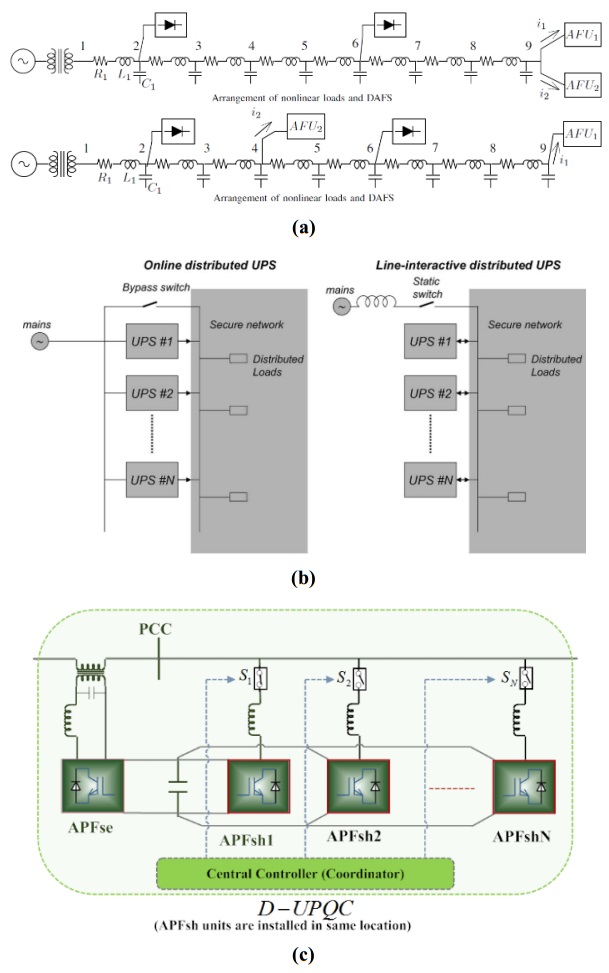
Cheng PT, Lee TL (2006) Distributed active filter systems (DAFSs): A new approach to power system harmonics. IEEE T Ind Appl 42: 1301–1309. doi: 10.1109/TIA.2006.880856
![]() |
[11] |
Guerrero JM, Hang L, Uceda J (2008) Control of distributed uninterruptible power supply systems. IEEE T Ind Electron 55: 2845–2859. doi: 10.1109/TIE.2008.924173
![]() |
[12] |
Lai J, Peng FZ (1996) Multilevel converters-a new breed of power converters. IEEE T Ind Appl 32: 509–517. doi: 10.1109/28.502161
![]() |
[13] |
Munoz JA, Espinoza JR, Moran LA, et al. (2009) Design of a modular UPQC configuration integrating a components economical analysis. IEEE T Power Deliver 24: 1763–1772. doi: 10.1109/TPWRD.2009.2028795
![]() |
[14] |
Peng FZ, Mckeever JW, Adams DJ (1998) A power line conditioner using cascade multilevel inverters for distribution systems. IEEE T Ind Appl 34: 1293–1298. doi: 10.1109/28.739012
![]() |
[15] |
Han B, Bae B, Baek S, et al. (2006) New configuration of UPQC for medium-voltage application. IEEE T Power Deliver 21: 1438–1444. doi: 10.1109/TPWRD.2005.860235
![]() |
[16] | Han B, Baek S, Kim H, et al. (2006) Dynamic characteristic analysis of SSSC based on multibridge inverter. IEEE Power Eng Rev 22: 62–63. |
[17] |
Han BM, Mattavelli P (2003) Operation analysis of novel UPFC based on 3-level half-bridge modules. IEEE Power Tech Conference Proceedings, Bologna. IEEE 4: 307–312. doi: 10.1109/PTC.2003.1304740
![]() |
[18] | Munoz JA, Espinoza JR, Baier CR, et al. (2011) Design of a discrete-time linear control strategy for a multi-cell UPQC. IEEE T Ind Electron 59: 3797–3807. |
[19] | Khadem MSK, Basu M, Conlon MF (2012) UPQC for power quality improvement in dg integrated smart grid network-a review. Int J Emerg Electr Power Syst 13: 3. |
[20] |
Basu M, Das SP, Dubey GK (2008) Investigation on the performance of UPQC-Q for voltage sag mitigation and power quality improvement at a critical load point. IET Gener Transm Dis 2: 414–423. doi: 10.1049/iet-gtd:20060317
![]() |
[21] |
Khadem S, Basu M, Conlon M (2014) Harmonic power compensation capacity of shunt apf and its relationship to design parameters. IET Power Electron 7: 418–430. doi: 10.1049/iet-pel.2013.0098
![]() |
[22] |
Corradini L, Mattavelli P, Corradin M, et al. (2010) Analysis of parallel operation of uninterruptible power supplies loaded through long wiring cables. IEEE T Power Electr 25: 1046–1054. doi: 10.1109/TPEL.2009.2031178
![]() |
[23] |
Guerrero JM, Matas J, Castilla M, et al. (2006) Wireless-control strategy for parallel operation of distributed-generation inverters. IEEE T Ind Electron 53: 1461–1470. doi: 10.1109/TIE.2006.882015
![]() |
[24] | Khadem SK, Basu M, Conlon MF (2011) A review of parallel operation of active power filters in the distributed generation system. European Conference on Power Electronics and Applications. IEEE, 1–10. |
[25] | Arrillaga J, Liu YH, Watson NR (2007) Self-commutating conversion, in flexible power transmission: The HVDC options. John Wiley & Sons, Ltd, Chichester, UK. |
[26] | Khadem SK, Basu M, Conlon MF (2013) Selection of design parameters to reduce the zero-sequence circulating current flow in parallel operation of DC linked multiple shunt APF units. Adv Power Electron 2013: 13. |
[27] |
Asiminoaei L, Aeloiza E, Enjeti PN, et al. (2008) Shunt active-power-filter topology based on parallel interleaved inverters. IEEE T Ind Electron 55: 1175–1189. doi: 10.1109/TIE.2007.907671
![]() |
[28] |
Chen TP (2012) Zero-sequence circulating current reduction method for parallel HEPWM inverters between AC bus and DC bus. IEEE T Ind Electron 59: 290–300. doi: 10.1109/TIE.2011.2106102
![]() |
[29] | Ye Z, Boroyevich D, Choi JY, et al. (2006) Control of circulating current in parallel three-phase boost rectifiers. Applied Power Electronics Conference and Exposition, 2000. IEEE 1: 506–512. |
[30] |
Chen TP (2006) Circulating zero-sequence current control of parallel three-phase inverters. IEE P-Elect Pow Appl 153: 282–288. doi: 10.1049/ip-epa:20050231
![]() |
[31] | Abdelli Y, Machmoum M, Khoor MS (2004) Control of a multi module parallel able three phase active power filters. International Conference on Harmonics and Quality of Power. IEEE, 543–548. |
[32] | Wei X, Dai K, Fang X, et al. (2006) Parallel control of three-phase three-wire shunt active power filters. Automat Electr Power Syst 31: 70–74. |
1. | S. Lakshmi Kanthan Bharathi, S. Selvaperumal, MGWO-PI controller for enhanced power flow compensation using unified power quality conditioner in wind turbine squirrel cage induction generator, 2020, 76, 01419331, 103080, 10.1016/j.micpro.2020.103080 | |
2. | Sumit K. Rathor, D. Saxena, Energy management system for smart grid: An overview and key issues, 2020, 44, 0363-907X, 4067, 10.1002/er.4883 | |
3. | Angelo Raciti, Santi Agatino Rizzo, Giovanni Susinni, Circuit model of LED light bulb suitable for typical voltage THD on LV distribution networks, 2020, 212, 03787788, 109665, 10.1016/j.enbuild.2019.109665 | |
4. | Oladepo Olatunde, Mohammad Yusri Hassan, Md Pauzi Abdullah, Hasimah Abdul Rahman, Hybrid photovoltaic/small-hydropower microgrid in smart distribution network with grid isolated electric vehicle charging system., 2020, 31, 2352152X, 101673, 10.1016/j.est.2020.101673 | |
5. | Nitasha Khan, Zeeshan Shahid, Muhammad Mansoor Alam, Aznida Abu Bakar Sajak, M. S. Mazliham, Talha Ahmed Khan, Syed Safdar Ali Rizvi, Xuan Wu, Energy Management Systems Using Smart Grids: An Exhaustive Parametric Comprehensive Analysis of Existing Trends, Significance, Opportunities, and Challenges, 2022, 2022, 2050-7038, 1, 10.1155/2022/3358795 | |
6. | Elżbieta Sztajmec, Paweł Szcześniak, A Review on AC Voltage Variation Compensators in Low Voltage Distribution Network, 2023, 16, 1996-1073, 6293, 10.3390/en16176293 |
Cases | Sag | APFse | APFsh1 | APFsh2 |
Case A | $X\left({k = 0} \right)$ | $X$ | $\surd $ | $X$ |
Case B | $X\left({k = 0} \right)$ | $X$ | $\surd $ | $\surd $ |
Case C | $\surd \left({k = 0.2} \right)$ | $\surd $ | $\surd $ | $\surd $ |
Case D | $\surd \left({k = 0.2/0.5} \right)$ | $\surd $ | $\surd $ | $\surd $ |
Conditions | 0.0–0.1 | 0.1–0.2 | 0.2–0.3 | 0.3–0.4 | 0.4–0.5 |
$Sag$ | $\surd $ | $\surd $ | |||
$\mathit{\boldsymbol{APFse}}$ | $\surd $ | $\surd $ | |||
$Loa{d_1}$ | $\surd $ | $\surd $ | $\surd $ | $\surd $ | |
$\mathit{\boldsymbol{APFsh}}{\bf{1}}$ | $\surd $ | $\surd $ | $\surd $ | $\surd $ | |
$Loa{d_2}$ | $\surd $ | $\surd $ | |||
$\mathit{\boldsymbol{APFsh}}{\bf{2}}$ | $\surd $ | $\surd $ |
Component | Rating (Max) |
${I_{Tr -se}}$ | 210 A |
${I_{sh1 -rated}}$ | 80 A |
${I_{sh2 -rated}}$ | 50 A |
${I_{l1}}\left({p, q + h} \right)$ | 100 A, 68 A |
${I_{l2}}\left({p, q + h} \right)$ | 72 A, 55 A |
$\alpha $ | 5% |
$\beta $ | 5% |
$k$ | 0.2–0.5 |