
Citation: Ajitanshu Vedrtnam, Kishor Kalauni, Sunil Dubey, Aman Kumar. A comprehensive study on structure, properties, synthesis and characterization of ferrites[J]. AIMS Materials Science, 2020, 7(6): 800-835. doi: 10.3934/matersci.2020.6.800
[1] | Yan-Xia Dang, Zhi-Peng Qiu, Xue-Zhi Li, Maia Martcheva . Global dynamics of a vector-host epidemic model with age of infection. Mathematical Biosciences and Engineering, 2017, 14(5&6): 1159-1186. doi: 10.3934/mbe.2017060 |
[2] | Maria Guadalupe Vazquez-Peña, Cruz Vargas-De-León, Jorge Velázquez-Castro . Global stability for a mosquito-borne disease model with continuous-time age structure in the susceptible and relapsed host classes. Mathematical Biosciences and Engineering, 2024, 21(11): 7582-7600. doi: 10.3934/mbe.2024333 |
[3] | Rundong Zhao, Qiming Liu, Huazong Zhang . Dynamical behaviors of a vector-borne diseases model with two time delays on bipartite networks. Mathematical Biosciences and Engineering, 2021, 18(4): 3073-3091. doi: 10.3934/mbe.2021154 |
[4] | Rocio Caja Rivera, Shakir Bilal, Edwin Michael . The relation between host competence and vector-feeding preference in a multi-host model: Chagas and Cutaneous Leishmaniasis. Mathematical Biosciences and Engineering, 2020, 17(5): 5561-5583. doi: 10.3934/mbe.2020299 |
[5] | Yanxia Dang, Zhipeng Qiu, Xuezhi Li . Competitive exclusion in an infection-age structured vector-host epidemic model. Mathematical Biosciences and Engineering, 2017, 14(4): 901-931. doi: 10.3934/mbe.2017048 |
[6] | Alian Li-Martín, Ramón Reyes-Carreto, Cruz Vargas-De-León . Dynamics of a dengue disease transmission model with two-stage structure in the human population. Mathematical Biosciences and Engineering, 2023, 20(1): 955-974. doi: 10.3934/mbe.2023044 |
[7] | Xinli Hu, Yansheng Liu, Jianhong Wu . Culling structured hosts to eradicate vector-borne diseases. Mathematical Biosciences and Engineering, 2009, 6(2): 301-319. doi: 10.3934/mbe.2009.6.301 |
[8] | Pengyan Liu, Hong-Xu Li . Global behavior of a multi-group SEIR epidemic model with age structure and spatial diffusion. Mathematical Biosciences and Engineering, 2020, 17(6): 7248-7273. doi: 10.3934/mbe.2020372 |
[9] | Andrey V. Melnik, Andrei Korobeinikov . Lyapunov functions and global stability for SIR and SEIR models withage-dependent susceptibility. Mathematical Biosciences and Engineering, 2013, 10(2): 369-378. doi: 10.3934/mbe.2013.10.369 |
[10] | Jinliang Wang, Ran Zhang, Toshikazu Kuniya . A note on dynamics of an age-of-infection cholera model. Mathematical Biosciences and Engineering, 2016, 13(1): 227-247. doi: 10.3934/mbe.2016.13.227 |
Cardiovascular disease (CVD) is a leading cause of death worldwide, and accounts for over 30% of annual global fatalities [1]. In turn, ischemic heart disease is a frontrunner of global CVD mortality (age-standardized rate of 108.8 deaths per 100000 individuals). Prevalent cases of total CVD nearly doubled from 271 million in 1990 to 523 million in 2019, and the number of CVD deaths have steadily increased from 12.4 million in 1990, to 18.6 million in 2019, and more recently to 19.8 million in 2022 [1],[2]. In the setting of these rapidly growing cases and coronary disease burden, understanding the nuances of complex calcific coronary lesions has become paramount.
Coronary artery calcium (CAC) is a well-established, widely available, and highly specific marker of subclinical and advanced atherosclerosis [3],[4]. Computed Tomography (CT) facilitates the calculation of the CAC score, which is an independent predictor of coronary events in both asymptomatic and symptomatic individuals. CAC remains a vital adjudicator of atherosclerotic cardiovascular disease (ASCVD) and facilitates the up- or down-stratifying of asymptomatic, intermediate risk patients [3],[4]. CAC testing accounts for both stroke and coronary heart disease; additionally, it provides a model for either initiating or intensifying preventative pharmacotherapies [3]–[5]. And yet, the high prevalence of CAC in coronary heart disease (CHD) patients makes the percutaneous treatment of heavily calcified coronary lesions challenging. These cases have a higher risk of immediate complications, late failures due to stent underexpansion or malapposition, and poor clinical outcomes [5]. In this setting, understanding lesion pathophysiology and characterizing calcium deposition with multimodal imaging are crucial steps to improve the successful treatment of these lesions.
This backdrop lays a critical foundation for the following review. Here, we discuss CAC in the context of complicated and severely calcified lesions. We seek to ameliorate clinical uncertainties and synthesize growing amounts of research to help encourage a homogenous approach to complex calcific coronary lesions. To that end, this comprehensive review paper will first cover epidemiology, pathophysiology, and the types of calcific lesions. Next, we will review acute and long-term complications, as well as lesion preparation and intervention. Last, this review will explore the role of imaging and the contemporary management of these calcified lesions.
This review will begin by discussing the epidemiology of heavily calcified coronary stenosis. Generally, the prevalence of CAC relies upon age and gender. CAC occurs in over 90% of men and 67% of women above the age of 70 [5],[6]. Additional risk factors increase the susceptibility to global CAC, which are independent to lesion severity: an elevated body mass index (BMI), increased blood pressure, dyslipidemia, glucose disorders, familial history of CAC, cigarette smoking, chronic kidney disease (CKD), an elevated fibrinogen level, and a high C-reactive protein level [5],[7]. More specifically, recent registries and meta-analyses have estimated that the prevalence of moderate to severe calcific coronary stenoses ranges between 18 and 26% [8]–[11]. More importantly, severe calcific lesions are associated with advanced age in addition to the aforementioned comorbidities such as systemic hypertension, dyslipidemia, diabetes, and CKD [8],[12].
Of note, the pathophysiology of peripheral and coronary calcifications differs. Medial calcification is typically found within peripheral arteries (i.e., those of the extremities). There, calcium deposition is driven by osteoblast-like cells in tandem with systemic factors such as hypercalcemia, hyperphosphatemia, parathyroid hormone abnormalities, renal dysfunction (specifically reduction of the glomerular filtration rate), and dialysis duration.
In contrast, atherosclerotic CAC deposition relies upon dysmorphic calcium precipitation. Coronary calcification is driven by chondrocyte-like cells and is associated with the expression of a myriad of inflammatory factors (i.e., pro-inflammatory cytokines released by tissue macrophages and foam cells, as well as TNF alpha, PKC, ERK1/2, and JNK signaling pathways) [8],[11],[13]. Inflammation likely precedes the calcification process and plays an ongoing, synergistic role in calcium progression. Unlike peripheral artery calcification within the media, atherosclerotic coronary calcification deposits predominantly within the intima. The calcification process is kickstarted by the death of inflammatory cells and vascular smooth muscle cells (VSMCs), and the subsequent recruitment of macrophage-derived matrix vesicles. This fusion of cell debris originating from VSMC apoptosis serves as the focal site for calcium phosphate crystal formation. As cholesterol deposits are trapped under the endothelium, an intense inflammatory cascade ensues and yields the development of microcalcifications [5],[8].
Initial microcalcification areas within the coronaries typically range in size between 0.5 and 15.0 µm [14],[15]. At this stage, calcific deposits are detectible only on histopathology, via special stains such as von Kossa and Alizarin red. However, over time, micro lesions may coalesce into larger volumes and form masses known as speckles and calcified sheets. These counterparts, in turn, are clinically detectable via CT or intravascular imaging modalities. Large subintimal protruding calcifications increase the risk for plaque rupture, erosion, destabilization, and even thrombus formation [8],[12].
The development of calcific lesions is further spurred by the differentiation of pericytes and VSMCs. In fact, VSMCs themselves undergo trans-differentiation to osteoblast-like cells. They recruit calcifying matrix vesicles and secrete factors which, in turn, decrease the osteoclast-like cell's mineral resorbing activity [5],[16]. In the setting of local collagen fiber degradation, this cyclical process stimulates additional bone deposition and necrotic core formation [8],[12]. A relative lack of calcification inhibitory factors (such as matrix gamma-carboxyglutamic acid protein, pyrophosphate, fetuin-A, osteopontin, and osteoprotegerin) exacerbates the imbalance between osteogenic and osteoclastic mechanisms within the atheroma [8]. While the entire mechanism of CAC progression remains under investigation, the receptor activator of the nuclear factor-kappaB ligand/osteoprotegerin pathway is a hypothesized link between osteoporosis and CAC [16].
More recently, MicroRNAs (miRs) have been identified as important calcific regulators within atheroma sites. MiRs direct not only the VSMCs' complex genetic reprogramming, but the functional responses of other cell types that are important for vascular calcification [17]. Studies show that certain miRs which target Runx2 (i.e., miR-133 and miR-204) are down-regulated within aortic smooth muscle cells, which leads to calcification in vitro. Other trials investigate transcription factors such as osterix, which is a known miR-125b target. The respective inhibition of miR-125 is associated with increased Runx2 and osterix expression, in addition to elevated alkaline phosphatase activity and VSMC calcification [5],[18],[19]. Moreover, bone morphogenetic proteins (BMPs) and mitochondria are known regulators of calcium deposition. BMP2 and BMP4 are two specific osteogenic differentiation factors that have been identified within calcified atherosclerotic vessels [20]. Mitochondrial damage, in turn, has also been evidenced to play a key role in the calcification process of VSMCs. Alterations in VSMC phenotypes correlate with unique characteristics of mitochondrial metabolism, and calcified blood vessels are frequently accompanied by mitochondrial dysfunction and oxidative stress damage. In essence, mitochondria affect vascular calcification in three ways [21]. First, direct damage to mitochondrial DNA impairs the electron transport chain. Second, mitochondria directly participate in vascular calcification development by an oxidative stress injury. Last, mitochondria-driven autophagy, mitophagy, and apoptosis regulate the excretion of extracellular and matrix vesicles that drive the development of calcification [21].
Interestingly, valvular calcification also shares several biologic events with calcific coronary lesions [22]. For instance, aortic valve calcification similarly involves coordinating the actions of valve endothelial and interstitial cells. Like within the coronaries, these cells are synergized with a myriad of circulating inflammatory, immune, and bone marrow-derived cells. The latter are known to undergo a phenotypic transition to become osteoblast-like cells, which subsequently elaborate the bone matrix, encourage the endothelial-to-mesenchymal transition, and build matrix vesicles which form the seedbed of microcalcification development [22]. While valvular calcification is highly prevalent worldwide and is associated with significant CV morbidity and mortality, a continued discussion of valvular lesions is beyond the scope of this paper.
Calcifications may manifest as numerous morphologies within a vessel: microcalcifications, spotty calcifications, and large calcifications [11]. Prognosis and treatment options heavily depend upon the morphology type; thus, a proper characterization is important. While calcification represents a more stable lesion than its soft plaque counterparts, its management cannot be underestimated.
Microcalcifications are typically within the 0.5 to 15 µm range: too small to be visualized on cardiac CTA. They represent the starting lesions within the calcification cascade. Spotty calcification, in turn, is classified as a visually detectable lesion ≤3 mm in any direction within a plaque. Last, large calcifications are defined as deposits with an arc of >90° on optical coherence tomography (OCT) [11]. Plaque morphology directly impacts lesion risk and prognosis, and numerous trials have investigated these impacts. The Incident COroNary Syndromes Identified by Computed Tomography (ICONIC) Trial found a hazard ratio of 1.543 (1.169–2.037) for spotty calcification as an acute coronary syndrome (ACS) precursor [11],[23]. Other studies similarly found spotty calcification to be a high risk finding on intravascular ultrasound (IVUS). This morphology was frequently associated with extensive and accelerated ASCVD progression [24]. Similarly, Kataoka et al. demonstrated an increased plaque vulnerability on OCT with the presence of spotty calcification [25]. Large calcification, in contrast, correlates inversely with plaque rupture and suggests a higher plaque stability [26]. And yet, these morphologies are not isolated predictors of calcific lesion risk; stability versus risk also depends upon plaque and local inflammation surrounding calcium deposition [11].
In addition to the size and shape, calcific lesions may be phenotypically characterized by spatial position (Figure 1). As appreciated in Figure 1, this classification method includes the following morphologies: superficial, concentric, eccentric, and calcified nodules. Calcium is considered superficial when present at the intimal-lumen interface, or closer to the lumen than the adventitia. In turn, lesions are considered deep when located at the media-adventitia border, or closer to the adventitia than to the lumen [27]. In contrast, eccentric calcium requires calcification over <3 quadrants of the vessel lumen circumference, while concentric calcium requires a cross-section lesion >3 quadrants of the vessel circumference. During balloon dilation, eccentric lesions may result in luminal gain via disruption or stretching of the noncalcified vessel wall. This may predispose eccentric lesions to small dissections at the shoulder of calcified plaques. In contrast, balloon dilation of concentric calcium causes fractures in thinner, weaker areas of calcium [27]. To this end, classifying the precise length and depth of calcified lesions remains paramount for proper percutaneous coronary intervention (PCI) planning, optimization, and strategy.
Next, this paper will transition from calcific lesion morphology and pathogenesis. Now, we will discuss important clinical scenarios that involve severely calcified lesions: acute coronary syndromes (ACS), chronic total occlusions, and bifurcation lesions.
Coronary calcification, particularly with respect to severely calcified lesions, affects both revascularization strategies and clinical outcomes of patients with ACS. ACS events result from an acute occlusive coronary thrombosis, which is most commonly driven by lipid plaque ruptures and the release of thrombogenic substrates. Less often, fatal acute coronary thrombosis may be caused by calcified nodules themselves (incidence 2–7%) [28]. In these instances, distinct calcified plaque types have been identified as the culprit lesion in ACS events: superficial calcific sheets, eruptive calcified nodules, and calcified protrusions. Although the superficial calcific sheet is the most common, it holds the poorest baseline thrombolysis in myocardial infarction (TIMI) flow and smallest lumen diameter, as well as the highest risk of post-PCI myocardial damage [28]. While small calcium deposits trigger the destabilization of lipid plaques, extensive calcification suggests advanced atherosclerosis and may signify plaque stability. Regardless, calcified plaques are frequently identified as the culprit lesion in ACS patients (even without the presence of a ruptured lipid core) [28].
Sanchez et al. completed a post hoc analysis of the MATRIX (Minimizing Adverse Hemorrhagic Events by Trans-radial Access Site and Systemic Implementation of Angiox) Trial and used major adverse cardiac events (MACE) as the primary endpoint to assess ACS outcomes by calcium burden [29]. The coronary calcification of 7446 patients was examined. 11.7% presented with severe calcification on coronary angiography, and fewer patients with severe calcium burden underwent PCI than those with mild calcification. Instead, this high disease subgroup found a higher frequency of coronary artery bypass grafting and medical therapy-only than their non-severe counterparts. By 1-year, MACE occurred in 27.1% of patients with severe calcified coronary lesions and in 15% without severe coronary calcified lesions (HR 1.91; 95% CI 1.66–2.20, p < 0.001) [29]. All-cause mortality was 8.6% in patients presenting with and 3.7% in those without severe coronary calcification (HR 2.38, 1.84–3.09, p < 0.001). Last, patients with severe coronary calcification also incurred a higher rate of myocardial infarction (MI) (20.1% vs. 11.5%, HR 1.81; 95% CI 1.53–2.1, p < 0.001) [29]. Independent of the interventional management strategy, this study found that patients with ACS and severe coronary calcification had significantly worse clinical outcomes than their non-severe counterparts.
Like with ACS events, severe coronary calcification plays a significant role in the pathogenesis and management of chronic total occlusions. Chronic total coronary occlusions (CTOs) are classified by the complete occlusion of a coronary artery, for a duration greater than 3 months based on angiographic evidence. More specifically, the TIMI flow grading system facilitates a scoring classification from 0–3, dependent upon the degree of coronary blood flow assessed during angiography. In this regard, a true CTO must have 100% occlusion of a coronary artery with a TIMI flow grade of 0. In contrast, a functional CTO is defined as severely stenotic, but with a <100% occlusion and a TIMI 1 flow for a duration greater than 3 months per angiographic evidence [30].
CTO prevalence ranges from 33% to 52% in ischemic heart disease patients; however, these occluded segments contain a variable degree of calcification (as well as vascular tissue, lymphocytic infiltrate, fibrous tissue, and atheroma). Importantly, the later stages of CTOs correlate with larger focal calcifications and intraoccclusion enhancements [30],[31]. In fact, intraplaque calcification exacerbates the existing challenges of percutaneous CTO treatment. Intraplaque calcification remains a well-known predictor of technical failure for a myriad of reasons: it contributes to the uncrossable and undilatable nature of lesions (affecting up to 6% and 12% of lesions, respectively); and it increases the risk of procedural complications such as perforations [30]. Heavy calcification often prevents wire advancement within the intraplaque space, and forces interventionalists to use extraplaque techniques that are associated with a higher periprocedural risk. Intraplaque calcium makes advancing balloons and deploying stents challenging, all of which contribute to poor stent expansion: a major predictor of stent thrombosis and restenosis [32].
Seeing as moderate-severe CTO calcifications affect 58% of PCI candidates, these challenges are by no means infrequently encountered [30]. Ito et al.'s retrospective cohort of 285 patients that underwent CCTA before CTO PCI demonstrated that CTO PCI in patients with severe calcium yielded higher rates of in-stent restenosis and target lesion failure. Additionally, the investigators found that severe calcification was an independent predictor of adverse outcomes [32],[33]. Similarly, in a cohort of 1453 CTO PCI patients, Karacsoni et al. showed that moderate-to-severe coronary calcium correlated with lower technical and procedural success rates [34]. Moreover, MACE incidence was significantly higher in patient groups with heavily calcified CTOs (3.7% vs 1.8%; p = 0.033). Heavily calcified CTOs were similarly associated with longer procedural times, higher radiation and contrast volumes, and more procedural complications (due to the increased need for dissection techniques as mandated by the presence of severe calcification) [30],[34].
In addition to their role within ACS and CTOs, severely calcified lesions may also be clinically contextualized by their contribution to bifurcation lesions. Coronary bifurcation lesions (CBLs) are classified by a major coronary artery stenosis adjacent to and/or including the ostium of a significant side branch [35]. CBLs are common, and account for approximately 15–20% of all PCIs.
Similar to ACS and CTOs, moderate-to-severe calcification of coronary bifurcation lesions is not uncommon. High calcification is once again associated with unfavorable long-term clinical outcomes, which is predominantly driven by its contribution to higher rates of repeat revascularization. Percutaneous coronary intervention of CBLs is frequently performed; however, it is considered a high-risk procedure with frequent periprocedural complications. Compared to noncalcified bifurcation lesions, calcified coronary lesions decrease final lumen diameters and reduce acute lumen gain with stenting [36].
Kim et al. investigated clinical outcomes according to calcification severity of bifurcation target lesions after PCI with DES, with a prospective, multicenter, observational study of 2897 patients. Moderate to severe calcification of target bifurcation lesions was observed in 608 (20.9%) patients, and a high calcification increased the adjusted risks of target lesion failure (hazard ratio [HR] 1.31, 95% confidence interval [CI]: 1.03–1.68, p = 0.031), target lesion revascularization (HR 1.36, 95% CI: 1.04–1.79, p = 0.027), and revascularization (HR 1.39, 95% CI: 1.09–1.78, p = 0.009) [36]. Hence, investigators demonstrated that moderate or severe calcium within coronary bifurcation target lesions was associated with an increased 3-year risk of target lesion failure after PCI with DES, compared with no or mild calcification. Similar to ACS and CTOs, bifurcation lesions are an important clinical scenario that involve the necessary mitigation of severe calcifications.
Severe calcification within atherosclerotic lesions notably increases the complexity of PCIs. The rigidity introduced by calcified lesions impedes essential PCI steps, including vessel wiring, balloon deployment, and stent expansion [37]. Such obstacles elevate the risk of adverse outcomes such as stent underexpansion, stent thrombosis, in-stent restenosis, vessel dissection, and perforation, which collectively heighten the incidence of MACE and various complications [8]. Below, we will discuss notable contributing factors and consequences (summarized by Figure 2).
The challenge of lesion crossability is accentuated in the presence of heavily calcified and rigid plaques. These resist conventional interventional devices, thereby complicating and lengthening the PCI process [38]. To address these challenges, several options to improve lesion crossability during PCI have been developed. This includes rotational atherectomy (RA) and orbital atherectomy (OA), intravascular lithotripsy (IVL), cutting and scoring balloons, high-pressure balloon angioplasty, excimer laser coronary angioplasty (ELCA), and intravascular imaging techniques such as IVUS and OCT [37],[39]. These strategies will be discussed at greater length in a future section.
Relatedly, calcified plaques also exacerbate the risk of equipment loss and entrapment during PCIs. Their resistance complicates catheter navigation and effective balloon and stent deployment [40]. Typically, the use of atherectomy devices and high-pressure balloons is necessary to effectively navigate or modify these obstructions. However, the mechanical stress on these devices, especially when navigating through or altering calcified plaques, may lead to component loss, entrapment, and failure. A 2012 study by Iturbe et al. found that among the sample of 2338 PCIs included in the study, device loss or entrapment occurred in 9 (0.38%; 95% CI: 0.18–0.73%) and 4 cases (0.17%; 95% CI: 0.05–0.44%), respectively. Although rare, such failures pose immediate procedural risks and may necessitate repeat interventions or cardiac surgery [37],[41],[42].
Stent under-expansion, a major complication in PCI, occurs when a stent fails to reach its optimal diameter within a coronary artery. Primarily, this results from severely calcified lesions that resist expansion. This complication not only hampers the stent's adherence to the arterial wall but also compromises its structural integrity by creating gaps, which can disrupt blood flow and elevate the risk of stent thrombosis. Additionally, inadequate pressure exerted upon the arterial wall by under-expanded stents can potentially delay the vessel's healing process and encourage neointimal hyperplasia, which can lead to restenosis [43],[44].
The physical properties of calcifications often contribute to stent under-expansion itself. Lesion thickness, length, and circumferential extent definitively affect risk. Ultimately, stent under-expansion requires a multifaceted approach for effective management. This involves a combination of advanced plaque modification techniques (i.e., RA, OA, ELCA, cutting and scoring balloons, and IVL) and the strategic use of imaging modalities (i.e., IVUS and OCT) to guide treatment and ensure optimal outcomes [43]–[45].
In addition to the inherent challenges of stent deployment and equipment handling, PCI for calcified plaques create acute risks associated with arterial wall damage. Acute complications such as coronary artery dissection and perforation are rooted in increased mechanical stress from balloon inflation and atherectomy devices. In any case, these complications are more pronounced with calcified lesions [8],[38].
A recent systematic review and meta-analysis of 3997 studies was conducted over a 38-year period (1982–2020) and included data from 5568191 PCIs. Investigators found that the overall incidence of coronary perforation was 0.39% (95% CI: 0.34–0.45%). While rare, approximately one in five coronary perforations resulted in tamponade (21.1%). Moreover, the frequency of severe (Ellis III) perforations represented 43% of all cases, and perforation mortality was reported at 7.5% (95% CI: 6.7–8.4%) [46].
Risk mitigation necessitates careful patient and lesion assessments, and employs advanced imaging techniques such as IVUS or OCT to understand plaque composition and arterial structure. While techniques for lesion preparation and stent expansion have advanced, they still carry risks of coronary perforation and dissection. In the event of dissection, prompt stent deployment to seal the dissection can preserve blood flow. Here, IVUS is essential in providing detailed vessel architecture visualizations and prevents exacerbation of the dissection. In the event of perforation, treatment varies with severity and location. Strategies may include prolonged balloon inflation, or the use of covered stents for significant perforations. Rapid intervention is critical to prevent or address cardiac tamponade, and post-procedural monitoring is ultimately key to detect and manage any complications [38],[46].
Stent restenosis and thrombosis may occur even after a successful PCI, and they each highlight the complexities of managing calcified atherosclerotic plaques. These complications are influenced by procedural, patient-specific, and plaque-related factors, and they all significantly affect patient outcomes. In stent restenosis and thrombosis even possess a strong genetic component in their patient risk profile. Genetic studies have recently identified multiple loci associated with an increased susceptibility to thrombosis, as well as variations in drug metabolism [47].
The frequency of restenosis and thrombosis is dependent upon the degree of calcification, interventional techniques applied, and patient-specific factors. Despite the advancements in PCI, the incidence of restenosis has been reported to be between 5 and 10%, reaching as high as 20% in patients with type 2 diabetes. The mechanical stress during PCI, especially in the management of calcified plaques, can injure vessels and promote thrombotic processes [48]. PCI prompts a pronounced healing response, which increases the risk of restenosis. Central to this complication is neointimal hyperplasia: characterized by smooth muscle cell proliferation and migration to the arterial intima following PCI-driven vascular injury. This repair mechanism may result in tissue overgrowth within the stent or treated artery, thereby narrowing the arterial lumen and impeding blood flow [48]. Calcified plaques' inherent stiffness, coupled with vessels' natural elastic recoil, significantly contributes to post-procedural vessel narrowing. Stent under-expansion further aggravates this issue by providing a scaffold for neointimal tissue proliferation [49].
To mitigate restenosis risk, drug-eluting stents (DES) play a pivotal role by releasing medications (i.e., sirolimus) that inhibit smooth muscle cell proliferation. Complementary post-procedural dual antiplatelet therapy is similarly crucial for thrombosis prevention. Nonetheless, the need for innovation in DES design persists. Ultimately, personalized treatment approaches that consider genetic predispositions can further refine intervention choices and preventive strategies for at-risk individuals [48],[49].
Like with restenosis and thrombosis, severely calcified lesions elevate ACS risk. Mechanical interventions promote stress on the arterial wall, predisposing plaque rupture or fissuring. Mechanical disruption may expose the plaque's thrombogenic substrate to the bloodstream, initiating the clotting cascade and leading to thrombus formation. Angiographic evidence has shown that embolization occurs in up to 15% of patients who underwent PCI, while histologic evidence has demonstrated that thrombogenic material can be extracted in up to 73% of severely calcified cases [50]–[52].
Additionally, PCI intervention of calcified lesions increases the risk of side branch occlusion. Reduced blood flow to the myocardium served by these branches further exacerbates ischemic conditions. Infrequently, manipulation of severely calcified lesions during PCI can also provoke localized vasospasms, which acutely reduce blood flow and contribute to the ischemic processes underlying ACS.
The No-Reflow phenomenon refers to inadequate myocardial perfusion through a coronary segment after successful dilation and stenting. Lack of reflow persists even without any residual stenosis or occlusive dissection. Pathophysiologically, microvascular obstruction from dislodged calcific and atheromatous debris—compounded by local inflammation, ischemic injury from rapid reperfusion and oxidative stress, and capillary damage—explain this phenomenon [53],[54]. No-Reflow marks a significant challenge in PCI, specifically in association with large, calcified plaques that contain a pool of lipidic material [55].
A recent study by Hosoda et al. evaluated the association between calcified plaques and the no-reflow phenomenon post-PCI. Utilizing near-infrared spectroscopy and IVUS imaging, the REASSURE-NIRS registry assessed the maximum 4-mm lipid-core burden index (maxLCBI4mm) in stable CAD patients with either small (maximum calcification arc <180°; n = 272) or large (maximum calcification arc ≥180°; n = 189) calcification in target lesions. The study explored how maxLCBI4mm related to the corrected TIMI frame count (CTFC) and no-reflow incidents in these two groups. Findings showed that no-reflow occurred in 8.0% of the participants. In participants with large calcifications, 55.6% had maxLCBI4mm ≥400 compared with 56.2% in participants with small calcifications (p = 0.82). Importantly, a higher CTFC (p < 0.001) was also observed in the large calcification group. Investigators found that maxLCBI4mm at culprit lesions with large calcification increased the risk of no-reflow phenomenon after PCI [55].
Addressing severely calcified atherosclerotic lesions is further complicated by an increased risk of bleeding and vascular access complications (i.e. at catheter insertion sites). Incidence of hematomas, pseudoaneurysms, and arteriovenous fistulas are amplified by the nature of PCI's for severely calcified lesions: which necessitate extended durations and complex interventions [56].
In conclusion, the PCI of severely calcified atherosclerotic lesions embodies a paradigm of complexity and precision within interventional cardiology. The inherent challenges posed by these calcified lesions necessitate leveraging cutting-edge imaging technologies, advanced intervention devices, and a strategic pharmacological regimen. This paper will now turn its attention towards these topics.
The crux of optimizing patient outcomes in the context of PCI for severely calcified lesions lies within pre-procedural planning and interventional precision. This may include the strategic selection and use of a DES to curtail the incidence of restenosis, the employment of atherectomy devices for the effective preparation of the calcified plaques, and the use of intravascular imaging to ensure the accuracy of stent placement. Moreover, the careful management of antithrombotic therapy post-procedure is essential to balance minimizing thrombosis while mitigating bleeding risks, which ultimately calls for a tailored approach to each patient's unique clinical profile.
Imaging techniques for calcified plaque identification, pre-procedural planning, and assessment are paramount to optimizing patient outcomes. We will begin by discussing non-invasive strategies, of which Coronary CT Angiography (CCTA) is the most important (Figures 3 and 4).
Using the Agatston method, CT detects calcium by an area of hyper-attenuation of at least 1 mm2 with >130 Hounsfield units or ≥3 adjacent pixels [43]. A coronary artery calcium (CAC) score is subsequently calculated with the following protocol. First, a weighted value is assigned to the highest density calcification within each coronary segment (excluding valvular or aortic calcium) [43]. This value is then multiplied by total area, and later summed for all measured arteries. This yields a total CAC score: a widely available, exhaustively studied, and highly specific marker of subclinical atherosclerosis [3]. CAC is repeatedly evidenced as an excellent prognosticator for clinical events, serves as a vital arbitrator of ASCVD, and accounts for both stroke and coronary heart disease. CAC testing facilitates the up- or down-risking of asymptomatic patients and provides a model for initiating or intensifying preventive statin pharmacotherapies [57].
Administering contrast in coronary CT angiography yields a more nuanced assessment of calcification. CCTA facilitates an automatic reconstruction (3-dimensional maximum intensity projection) of calcium within the aorta and coronary tree. In doing so, CCTA helps visualize global calcium burden and distribution, and offers an initial automated appraisal of PCI complexity [58]. Coronary CTA is not only crucial for calcified plaque identification, but provides a model for individualizing primary ASCVD prevention and shared clinician-patient decision making [57].
CT–guided PCI uniquely offers comprehensive procedural planning and simultaneously incorporates calcific plaque characterization. In assessing the need for advanced calcium preparation, CCTA optimizes resource allocation and tailors procedural planning to each case's complexity. CCTA's role in the preprocedural phase also prompts intravascular imaging during PCI, and may signal the need for additional devices during plaque preparation. Understanding the type and complexity of disease prior to intervention permits optimal preparation of the material and personnel required, initial strategy, potential complications, as well as corrective actions. From a patient perspective, CT also offers an intuitive visualization of the upcoming procedure [58].
CCTA's color-coded 3D reconstructions are a novel way to evaluate calcium. Coronary CT angiography offers answers to important clinical questions: whether advanced calcium plaque modification should be employed and, if so, which device should be used. Particularly in complex cases with severe calcification, noninvasive calcium modalities are a valuable adjunct to intravascular techniques and a major innovation in the field of coronary CT and PCI.
CT-guided PCI with dedicated calcium evaluation is currently under investigation in a prospective randomized controlled trial, The Precise Procedural and PCI Plan (P4). The trial includes 1000 patients with hemodynamically significant lesions (as determined by fractional flow reserve derived from CT) and will be randomized to CT-guided PCI or IVUS-guided PCI. About 30% of the cohort will show severe calcification based on CT. P4's hypothesis is that comprehensive assessment by CCTA in planning and guiding PCI will yield comparable clinical outcomes to IVUS-guided PCI at 1-year follow-up. In this regard, P4 will help validate CT calcium analysis with intravascular and clinical outcomes. The trial's results are expected by 2026 [59].
Coronary angiography visualizes severely calcified lesions as radiopacities without cardiac motion before contrast injection, generally appreciated on both sides of the arterial lumen as a “tram-track” appearance [38]. However, angiography alone has poor sensitivity in identifying calcified lesions. This necessitates a space for modern intravascular imaging methods (Figures 3 and 4) to assess calcium presence, length, depth, and ultimately optimize PCI planning [43].
One such method is IVUS, the first catheter-based technology to evaluate disease within the vessel wall. IVUS employs two primary systems: one modality uses a solid-state approach, with a system externally mounted on a catheter and controlled electronically; and the second modality uses a mechanical approach, with a rotating internal cable that can measure lesion length and specific coronary plaque characteristics [27]. IVUS offers a lower resolution than its other imaging counterparts, but provides higher penetration depth [43]. At 40 MHz, IVUS axial resolution ranges between 100 and 150 µm and lateral resolution between 150 and 300 µm. At 60 MHz, axial resolution ranges between 40 and 60 µm and lateral resolution between 60 and 140 µm. Of note, these ranges are insufficient to optimally evaluate superficial plaque or post-PCI concerns [43].
IVUS first produces a grayscale image of plaque components. Given the challenge in visually interpreting these monotone images, numerous post-processing methods have been developed to facilitate tissue characterization. Color conversion algorithms based on tissue density include the following: virtual histology (VH), iMAP-IVUS (iMap-Intravascular Ultrasound Radiofrequency Signal Analysis), and IB-IVUS (integrated backscatter) [43]. Calcium is identified as hyperechogenic structures that shadow the underlying ultrasound anatomy (for this reason, IVUS cannot detect calcium thickness), appreciated as white spots on VH and quantified by measuring the lesion's circumferential extent. Calcified lesions on IVUS are qualitatively given either “superficial” or “deep” classifications, characterized by their greater proximity to lumen or adventitia, respectively [27]. In turn, semi-quantitative analysis is possible by assessing calcium arc and length [43]. However, IVUS is rarely able to identify intra-plaque microcalcifications. Seeing as microcalcifications increase local tissue stress and promote plaque rupture, this inadequacy represents a major IVUS limitation [43].
IVUS proves helpful for pre- as well as post-intervention evaluation. Frequently employed to investigate calcium ablation and rupture outcomes, IVUS is adept in assessing plaque fracture after shock-wave techniques or thinning of calcium thickness after rotational atherectomy. In this regard, IVUS offers critical guidance in adjudicating subsequent stent placement decisions [27].
OCT is another intravascular approach, more advanced than its IVUS counterpart. OCT employs a light-based imaging modality and relies upon infrared light wave emission, that reflects against the internal microstructure of coronaries and biological tissue. By measuring amplitude and time delay of backscattered light, OCT creates high-resolution, cross-sectional, and 3D volumetric images of vessel microstructure [43].
OCT's shorter infrared wavelength (1.3 µm) compared to IVUS' ultrasound wavelength (40 µm at 40 MHz) facilitates better axial resolution (10–20 µm versus 50–150 µm) [43]. To this end, OCT yields particularly excellent accuracy and boasts a 10-fold higher image resolution than IVUS [27]. OCT outstandingly characterizes individual structures of the coronary wall, remarkably stratifies plaque composition (i.e. presence or absence of thrombus, calcium, macrophages, or dissections), and exceptionally analyzes stent placement (i.e., identifying edge dissection, malapposition, or underexpansion). However, this aforementioned wavelength differential also contributes to OCT's lower penetration depth when compared to IVUS (1–2 mm versus 5–6 mm); this finding particularly limits OCT in the presence of highly attenuating structures like red thrombus or lipid/necrotic core [43].
While IVUS can assess calcification arc but not thickness, OCT can evaluate both. In this regard, OCT surpasses IVUS' more simple classification system. OCT helps categorize calcium not only by deep or superficial position, but by a nodular, eccentric, or concentric presentation [27]. In doing so, OCT empowers precise definitions of lesion length and circumferential extension. OCT maintains a fundamental position in treating calcified plaque. Each calcified lesion is unique, and thus it requires an individualized intervention and a tailored therapeutic approach.
Now, this paper will transition from its discussion of imaging to calcified coronary lesion treatment techniques (Figures 3 and 4). Patients with moderate-severe calcified lesions pose a unique challenge to PCI, and their cases often require specialized intervention strategies. Severe calcification requires exceptional lesion preparation, and evaluating plaque distribution is essential to optimize treatment outcomes.
Non-compliant (NC) balloon angioplasty is considered first-line for patients with mild to moderate calcified plaque, to facilitate optimal stent expansion. NC balloons are composed of polyethylene terephthalate and are characterized by rigid, thick walls which allow for high-pressure inflation and maximum dilation of target stenotic lesions [60]. Of note, these balloons only expand to 110% of their total size: less than their semi-compliant or compliant counterparts (which expand to 130%) [60].
While NC balloons' rigid structure reduces their risk of overexpansion, this inflexibility makes them less suited for anatomical constraints or vessel irregularities. Particularly with severely calcified lesions, non-uniform balloon expansion steepens risk of coronary dissection, coronary perforation, and balloon rupture. These complications are attributed to NC's rigid design, which yields excessive pressure at inflexible balloon edges [38]. While NC balloon angioplasty remains a helpful adjunct to atherectomy in most cases, alternative balloon modalities (i.e. scoring, cutting, or ultrahigh) should be considered in cases of severe calcification [60].
Cutting balloons (Flextome and Wolverine, Boston Scientific) are a specialized type of non-compliant balloon. They are characterized by three mounted blades or microtomes, which create discreet incisions in the calcified plaques upon inflation. In doing so, cutting balloons generate small calcium fractures, which reduce elastic recoil after predilation and increase luminal gain.
These mounted blades provide exceptional incision control and enable deeper penetration of target calcified plaques. Cutting balloons employ a lower nominal pressure than classic noncompliant balloons, which minimizes intimal trauma and decreases risk of arterial rupture or dissection. Of note, cutting balloons do not have the capability of removing calcium from the vessel. They are most effective when used for shorter lengths (i.e. 20 mm) and for pressures between 12 and 14 atm [44].
Despite these advantages, cutting balloons have yielded varying outcomes. The GLOBAL trial found that, with regard to reducing restenosis after angioplasty without stenting, cutting balloons were not superior to PCI [27]. Conversely, the REDUCE III Trial found that, with regard to restenosis and target lesion revascularization, cutting balloons (followed by bare metal stent implantation) were superior to percutaneous transluminal coronary angioplasty [27].
Scoring balloons (AngioSculpt, Philips; Scoreflex, OrbusNeich; Chocolate XD, Teleflex; NSE Alpha, B. Braun; and Lacrosse NSE, Asomedica) are characterized by a helical edge and covered by nitinol scoring elements [27]. This edge is composed of metal wires or blades, embedded in the balloon's surface and distributed in a helical pattern. Mechanistically, scoring balloons are similar to cutting balloons; their helical design creates controlled, superficial cuts within calcified plaques. These incisions weaken target plaque, improving arterial expansion and luminal gain [61]. Scoring balloons' low crossing profile also provides maximum flexibility and trackability, and they are generally considered less noncompliant than traditional balloons. In turn, scoring balloons possess more optimal diameter expansion and offer exceptional plaque modification [61].
Numerous studies have evidenced cutting balloons' high procedural success rate, thus supporting their use prior to stent implantation. Scoring balloons may even be preferred over cutting balloons. They possess a more deliverable profile, and their more superficial incisions decrease risk of perforation and dissection when compared with cutting balloons. Given their increased flexibility, scoring balloons are especially helpful in cases with challenging anatomical constraints [27]. For this reason, scoring balloons are frequently employed for in-stent restenosis and calcified lesions.
In contrast, ultrahigh pressure balloons (OPN NC, SIS Medical) differ from scoring and cutting balloons in both their design and mechanism of action. These are comprised of rapid-exchange noncompliant balloon catheters, which tolerate high pressures with only minimal increases in diameter [38]. Ultrahigh pressure balloons require no physical incision, and they uniquely apply significantly higher pressures than standard balloons during angioplasty. While standard angioplasty balloons have pressure ratings of 6–20 atm, ultrahigh pressure balloons can tolerate pressures above 30 atm [61]. These significant exertional forces maximize the expansion of heavily calcified lesions, allowing for improved blood flow. In this regard, ultrahigh pressure balloons are preferred over standard balloons in situations with heavy plaque burden. They can even be applied towards post-dilation to achieve optimal stent expansion. Moreover, ultrahigh pressure balloons have a better crossing profile than their cutting and scoring counterparts [27].
In a 2019 retrospective study of 326 patients, investigators found that this super high-pressure balloon successfully treated >90% of non-dilatable calcified coronary lesions. Of note, these lesions were ones that conventional noncompliant balloons had failed to adequately modify [62]. Unfortunately, however, coronary rupture occurred in 3 patients [62]. The recent ISAR-CALC Trial demonstrated that the OPN high pressure balloon performed as well as the scoring balloon with regard to lesion preparation, yet the first yielded a superior angiographic result [27].
Contemporary modalities for calcium modification—especially those for severely calcified lesions—are often more complex than preparation by balloon angioplasty. In these cases, percutaneous coronary intervention may be assisted by methods like intravascular lithotripsy or ablative strategies like atherectomy (Figures 3 and 4).
Intravascular lithotripsy (Shockwave C2 coronary IVL, Shockwave Medical) was adapted from nephrolithiasis treatment technology, and introduced to the coronary calcium sphere as recently as 2017 [27],[38],[43]. The IVL system uses a 0.014-inch guidewire-compatible, fluid-filled balloon angioplasty catheter. Its two lithotripsy emitters (placed proximally and distally) are incorporated into the catheter's shaft, and they convert electrical energy into acoustic pressure pulses. In turn, these pulses collide with calcium via expanding/collapsing vapor bubbles and create a transient burst of acoustic pressure waves. These pulsatile sonic pressure waves traverse coronary tissue with an effective 50 atm and selectively fracture the calcium both deeply (a unique lithotripsy ability which other ablation techniques do not possess) and superficially. Notably, the shock waves spare soft vessel tissue due to its elasticity. Compared to its ablative counterparts, IVL is also uniquely ideal for bifurcation lesions (i.e., left main coronary disease); the cardiologist can wire and protect both major branches during lesion preparation. In doing so, calcium fragments are minimally disrupted and remain within the subintima. With no significant release of downstream debris, IVL is unlikely to cause distal embolism [27],[38],[43].
IVL is user-friendly and has quickly become a standard approach for severe calcific coronary lesions. In fact, because the device is similar to standard PCI catheters, IVL requires no specific training beyond that for traditional atherectomy. Moreover, studies repeatedly demonstrate excellent early angiographic as well as late clinical outcomes. Post-IVL patients have improved vessel compliance, luminal gain, and stent expansion per OCT and are without significant complications (i.e., no evidence of dissection, slow flow or no reflow event, embolization, or coronary perforation) [27],[38],[43]. The DISRUPT CAD I study marked the first single-arm multicenter study, and it evidenced IVL's exceptional role in moderate-severe lesion preparation prior to stent delivery. This Trial found a reduction of stenosis to 12% and a luminal gain of 1.7 mm. After this pilot, the DISRUPT CAD II, III, and IV similarly indicated exceptional procedural success for IVL in severely calcified coronary lesions. A patient-level pooled analysis of the DISRUPT Trials (628 patients, 72 sites, 12 countries) demonstrated the following: a primary safety endpoint (absence of 30-day MACE) of 92.7% and an effectiveness endpoint (procedural success, defined as stent delivery with residual stenosis ≤30% and no in-hospital MACE) of 92.4% [27],[38],[43].
RA uses a high-speed, diamond-tipped burr that rotates within the lesion at speeds of up to 200000 revolutions per minute (rpm) [63]. The burr pulverizes calcific plaques into microparticles (5–10 microns in size) that are small enough to pass through the coronary circulation without causing significant embolic complications [64]. The ablation process selectively removes inelastic, calcified portions of the plaque while sparing the more elastic, healthy vessel wall, thus improving compliance and enabling optimal stent expansion [61],[63].
RA is primarily indicated for lesions classified as moderately to severely calcified, which often resist expansion by traditional balloon angioplasty. Lesions which cannot be sufficiently dilated by high-pressure or cutting balloons may also benefit from RA. Notably, the PREPARE-CALC randomized trial found that among 200 patients with MI and severely calcified native coronary lesions undergoing PCI, a strategy involving upfront RA before drug-eluting stent implantation was significantly more successful compared to using a modified balloon (MB). Strategy success was achieved in 98% of the RA group versus 81% of the MB group, resulting in a relative risk of failure of 9.5 for MB versus RA (95% CI: 2.3–39.7; p = 0.0001) [65].
According to the 2019 North American Expert Review of RA, the optimal technique involves several key elements to ensure effectiveness and safety. Mainly, the burr-to-artery ratio should be maintained between 0.4 and 0.6 to ensure that the burr is appropriately sized for the artery. Second, the burr rotational speed should range from 140000 to 150000 rpm to provide an efficient ablation of calcified lesions. Gradual burr advancement with a pecking motion is also crucial to ensure controlled progress and prevent damage to the vessel walls. In addition, the ablation runs should be kept short, between 15 and 20 seconds, to limit thermal injury and preserve the artery's integrity [66].
Thus, despite its benefits, RA carries inherent risks such as neointimal hyperplasia, vessel perforation, and dissection. Furthermore, the RA burr size can be limited by the guide catheter diameter and target vessel size, which restricts its use in certain anatomical settings [63].
Comparatively, IVL and RA show different performances and complication profiles. Studies that evaluated RA, such as ROTAXUS (n = 240) and PREPARE-CALC, revealed procedural success rates up to 98%, as mentioned, though with a risk of complications such as no-flow phenomena and MACE rates around 15% average one year post-intervention [65],[67]. IVL, as evidenced through the Disrupt CAD I-IV studies, demonstrated a slightly lower success at 92.4% and a small, potentially insignificant decrease in complications, such as incidence of MACE at one year (averaging 13.2%). Still, the very rare incidence of severe complications like vessel dissections in IVL is notable [67]. While both techniques have proven their effectiveness, IVL appears to offer a slightly safer profile in terms of fewer severe procedural complications, whereas RA might be somewhat more effective and appropriate for more severe and/or complicated cases of calcified lesions. Ultimately, the absence of comparative trials which evaluate these various techniques presents a substantial obstacle to discerning their utility, efficacy, and safety.
OA represents another advanced technique for the management of calcified coronary lesions. The OA system utilizes a diamond-coated crown that executes an orbital motion rather than a simple rotation, thereby effectively pulverizing calcified plaques. During intervention, the device progresses along a guidewire, and the crown rotates at speeds ranging from 80000 to 120000 rpm [63],[67]. It is available in two variants—the classic and the Micro Crown—the latter of which features a smaller distal tip that enhances maneuverability within narrower vasculature and expands the range of treatable lesions [67]. Similar to RA, OA efficiently removes hard, calcified deposits while preserving the structural integrity of the healthy vessel wall. Although RA is adept at ablating superficial calcium within coronary arteries, it generally does not address deeper calcium deposits [39]. Conversely, OA provides advantages for extensive lesions that encompass both superficial and deep calcium; OA's orbiting mechanism permits more controlled ablation and gradual vessel dilation with a reduced risk of perforation [8],[39].
Compared to other atherectomy modalities such as RA and IVL, one of the primary advantages of OA is its ability to maintain continuous blood flow during the procedure. This quality is key in enhancing microparticle clearance and minimizing thermal accumulation [8],[67]. Additionally, OA's ability to ablate both in the forward and reverse directions is particularly beneficial for complex lesions, and it mitigates the risk of burr entrapment, which may occur with RA [63].
In the context of OA, the ORBIT I trial (50 participants) achieved a procedural success rate of 94% (defined as residual stenosis of less than 20%) and reported six instances of coronary dissection [68]. The subsequent ORBIT II trial (443 participants) demonstrated a notably low in-hospital mortality rate of 0.2%—which was significantly lower than the 1.7% observed in the ROTAXUS trial for RA. Furthermore, ORBIT II recorded a procedural success rate of 89.1%, where 89.8% of patients remained event-free at the 30-day follow-up. The reported rate of MACE stood at 16.4% at 12 months [69]. Despite these findings, a definitive comparative assessment between OA and RA remains elusive, with no clear consensus favoring one technique over the other.
ELCA is a catheter-based intervention that utilizes ultraviolet laser energy to vaporize atherosclerotic plaques. It employs brief, high-energy laser pulses at a wavelength of 308 nm. Similar to other discussed techniques, though used infrequently, ELCA aims to reduce plaque burden in affected coronary vessels, thus facilitating subsequent interventional therapies such as balloon angioplasty or stent deployment [27],[63].
ELCA is particularly advantageous in managing non-crossable, non-dilatable fibrocalcific lesions and thrombotic components. In this regard, ELCA is most effective in complex anatomical settings including ostial lesions, bifurcations, and in-stent restenosis [70]. Thus, its capacity for selective tissue ablation and thrombus vaporization renders it an option in cases resistant to conventional mechanical atherectomies or angioplasties. The laser catheters, which are compatible with standard 0.014-inch guidewires, are available in four diameters—0.9, 1.4, 1.7, and 2.0 mm—to cater to varying severities and diameters of CAD. These catheters are designed as either concentric or eccentric based on the arrangement of laser fibers at the tip [38],[71].
Hassani et al. reported that the clinical-procedural success rates for ELCA in ISR ranged from 33% to 100%, with a median of 91%, as reported in the period from 1992 to 2018, and improved over time. However, significant drawbacks include potential renal complications from the use of contrast agents and limited efficacy on poorly visualized or heavily calcified plaques [72]. In fact, in heavily calcified lesions, its effectiveness decreases; instead, RA and OA become mainstay treatments. Another option is combining ELCA with RA, termed the RASER technique [71].
There are several notable risks associated with ELCA, especially linked with its photomechanical mechanism, which involves the use of a liquid medium (saline or blood) to form expanding bubbles that disrupt the plaque structure. Specifically, in the blood-infusion technique, blood proteins absorb much of the energy, thus increasing the formation of microbubbles and heightening the risk of traumatic dissection [72]. Ultimately, ELCA requires specialized expertise and generally incurs higher costs compared to mechanical atherectomy methods. Given this inaccessibility, it is reserved for select cases of non-crossable, non-dilatable lesions or as an adjunct to RA.
In conclusion, the choice among IVL, RA, OA, and ELCA should be tailored to lesion characteristics, vessel anatomy, operator experience, and economic considerations to optimize outcomes and to minimize complications in the treatment of calcific coronary lesions. Further studies, especially long-term, head-to-head RCTs, are essential to more accurately define the long-term outcomes and to establish optimal scenarios for each technique's application.
In summary, this review has highlighted the diversity of severely calcified coronary lesions, as well as their pathophysiologies and management strategies. We have covered the epidemiology, pathophysiology, lesion types, acute and long-term complications, lesion preparation, the role of intravascular imaging, and the contemporary management of these complex calcific lesions.
Understanding the nuances and challenges of calcified lesions promotes a model for individualizing their management and empowers shared clinician-patient decision making. This review has sought to ameliorate clinical uncertainties and synthesize growing amounts of research, to help encourage a homogenous approach to complex calcific coronary lesions. By summarizing the framework behind CAC and calcific lesion visualization, management, and intervention, this review paper helps advocate for global synthesis and applications in both the clinical and preventative setting. Helping physicians understand these themes is key to empower the most fitting choices in coronary calcification prevention and management.
All authors contributed evenly to the writing and researching of this project.
The authors declare they have not used Artificial Intelligence (AI) tools in the creation of this article.
[1] | Adam JD, Davis LE, Dionne GF, et al. (2002) Ferrite devices and materials. IEEE T Microw Theory 50: 721-737. |
[2] | Pullar RC (2012) Hexagonal ferrites: A review of the synthesis, properties and applications of hexaferrite ceramics. Prog Mater Sci 57: 1191-1334. |
[3] | Dairy ARA, Al-Hmoud LA, Khatatbeh HA (2019) Magnetic and structural properties of barium hexaferrite nanoparticles doped with titanium. Symmetry 11: 732. |
[4] | Snelling EC (1988) Soft Ferrites, Properties and Applications, Butterworth-Heinemann Ltd. |
[5] | Smit J, Wijn HPJ (1959) Ferrites, Eindhoven: Philips Technical Library, 150. |
[6] | Issa B, Obaidat I, Albiss B, et al. (2013) Magnetic nanoparticles: Surface effects and properties related to biomedicine applications. Int J Mol Sci 14: 21266-21305. |
[7] | Ammar S, Helfen A, Jouini N, et al. (2001) Magnetic properties of ultrafine cobalt ferrite particles synthesized by hydrolysis in a polyol medium. J Mater Chem 11: 186-192. |
[8] | Šutka A, Gross KA (2016) Spinel ferrite oxide semiconductor gas sensors. Sensor Actuat B-Chem 222: 95-105. |
[9] | Veena M, Somashekarappa A, Shankaramurthy GJ, et al. (2016) Effect of 60Co gamma irradiation on dielectric and complex impedance properties of Dy3+ substituted Ni-Zn nanoferrites. J Magn Magn Mater 419: 375-385. |
[10] | Krishnan V, Selvan RK, Augustin CO, et al. (2007) EXAFS and XANES investigations of CuFe2O4 Nanoparticles and CuFe2O4-MO2 (M = Sn, Ce) Nanocomposites. J Phys Chem C 111: 16724-16733. |
[11] | Vaidyanathan G, Sendhilnathan S (2008) Characterization of Co1-xZnxFe2O4 nanoparticles synthesized by co-precipitation method. Physica B 403: 2157-2167. |
[12] | Valenzuela R (2012) Novel applications of ferrites. Phys Res Int 2012: 591839. |
[13] | Kaur M, Kaur N, Verma V (2016) Ferrites: synthesis and applications for environmental remediation, Ferrites and Ferrates: Chemistry and Applications in Sustainable Energy and Environmental Remediation, American Chemical Society, 1238: 113-136. |
[14] | Haspers JM (1962) Ferrites: Their properties and applications, In: Hausner HH, Modern Materials, Elsevier, 3: 259-341. |
[15] | Shaikh PA, Kambale RC, Rao AV, et al. (2010) Structural, magnetic and electrical properties of Co-Ni-Mn ferrites synthesized by co-precipitation method. J Alloy Compd 492: 590-596. |
[16] | Jaswal L, Singh B (2014) Ferrite materials: A chronological review. J Int Sci Technol 2: 69-71. |
[17] | Saville P (2005) Review of radar absorbing materials. Defence Research and Development Atlantic Dartmouth (Canada). Available from: https://www.researchgate.net/publication/235178242_Review_of_Radar_Absorbing_Materials. |
[18] | Meng F, Wang H, Huang F, et al. (2018) Graphene-based microwave absorbing composites: A review and prospective. Compos Part B-Eng 137: 260-277. |
[19] | Abu-Dief AM, Abdel-Fatah SM (2018) Development and functionalization of magnetic nanoparticles as powerful and green catalysts for organic synthesis. BJBAS 7: 55-67. |
[20] | Kharisov BI, Dias HR, Kharissova OV (2019) Mini-review: Ferrite nanoparticles in the catalysis. Arab J Chem 12: 1234-1246. |
[21] | Kefeni KK, Mamba BB, Msagati TAM (2017) Application of spinel ferrite nanoparticles in water and wastewater treatment: A review. Sep Purif Technol 188: 399-422. |
[22] | Kumar M, Dosanjh HS, Singh J, et al. (2020) Review on magnetic nanoferrites and their composites as alternatives in waste water treatment: synthesis, modifications and applications. Environ Sci-Water Res 6: 491-514. |
[23] | Reddy DHK, Yun YS (2016) Spinel ferrite magnetic adsorbents: Alternative future materials for water purification. Coordin Chem Rev 315: 90-111. |
[24] | Stephen ZR, Kievit FM, Zhang M (2011) Magnetite nanoparticles for medical MR imaging. Mater Today 14: 330-338. |
[25] | Shokrollahi H, Khorramdin A, Isapour G (2014) Magnetic resonance imaging by using nano-magnetic particles. J Magn Magn Mater 369: 176-183. |
[26] | Pegoretti VCB, Couceiro PRC, Gonçalves CM, et al. (2010) Preparation and characterization of tin-doped spinel ferrite. J Alloy Compd 505: 125-129. |
[27] | Shokrollahi H, Avazpour L (2016) Influence of intrinsic parameters on the particle size of magnetic spinel nanoparticles synthesized by wet chemical methods. Particuology 26: 32-39. |
[28] | Ramimoghadam D, Bagheri S, Hamid SBA (2014) Progress in electrochemical synthesis of magnetic iron oxide nanoparticles. J Magn Magn Mate 368: 207-229. |
[29] | Sechovsky V (2001) Magnetism in solids: General introduction, In: Jürgen Buschow KH, Cahn RW, Flemings MC, et al., Encyclopedia of Materials: Science and Technology, Elsevier, 5018-5032. |
[30] | Gregersen E (2011) The Britannica Guide to Electricity and Magnetism, New York: Britannica Educational Publishing and Rosen Educational Services. |
[31] | Ferrimagnetism, Engineering LibreTexts (2020) Avaliable from: https://eng.libretexts.org/Bookshelves/Materials_Science/Supplemental_Modules_(Materials_Science)/Magnetic_Properties/Ferrimagnetism. |
[32] | Cullity BD, Graham CD (2008) Introduction to Magnetic Materials, 2 Eds., Wiley-IEEE Press. |
[33] | Hench LL, West JK (1990) Principles of Electronic Ceramics, Wiley. |
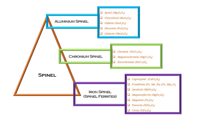
[34] | Biagioni C, Pasero M (2014) The systematics of the spinel-type minerals: An overview. Am Mineral 99: 1254-1264. |
[35] | Spinel: mineral, Encyclopedia Britannica (2020) Available from: https://www.britannica.com/science/spinel. |
[36] | Mineral gallery—The spinel group. Avaliable from: http://www.galleries.com/spinel_group. |
[37] | Biagioni C, Pasero M (2014) The systematics of the spinel-type mineralas: An overview. Am Mineral 99: 1254-1264. |
[38] | About: cuprospinel. Avaliable from: http://dbpedia.org/page/Cuprospinel. |
[39] | Nickel EH (1973) The new mineral cuprospinel (CuFe2O4) and other spinels from an oxidized ore dump at Baie Verte, Newfoundland. Can Mineral 11: 1003-1007. |
[40] | Pekov IV, Sandalov FD, Koshlyakova NN, et al. (2018) Copper in natural oxide spinels: The new mineral thermaerogenite CuAl2O4, cuprospinel and Cu-enriched varieties of other spinel-group members from fumaroles of the Tolbachik Volcano, Kamchatka, Russia. Minerals 8: 498. |
[41] | Fleischer M, Mandarino JA (1974) New mineral names. Am Mineral 59: 381-384. |
[42] | Manju BG, Raji P (2018) Synthesis and magnetic properties of nano-sized Cu0.5Ni0.5Fe2O4 via citrate and aloe vera: A comparative study. Ceram Int 44: 7329-7333. |
[43] | Liu Y, Wu Y, Zhang W, et al. (2017) Natural CuFe2O4 mineral for solid oxide fuel cells. Int J Hydrogen Energ 42: 17514-17521. |
[44] | Estrella M, Barrio L, Zhou G, et al. (2009) In situ characterization of CuFe2O4 and Cu/Fe3O4 water-gas shift catalysts. J Phys Chem C 113: 14411-14417. |
[45] | The mineral Franklinite. Avaliable from: http://www.galleries.com/Franklinite. |
[46] | Abdulaziz A, Wael HA, Kirk S, et al. (2020) Novel franklinite-like synthetic zinc-ferrite redox nanomaterial: synthesis, and evaluation for degradation of diclofenac in water. Appl Catal B-Environ 275: 119098. |
[47] | Lucchesi S, Russo U, Giusta AD (1999) Cation distribution in natural Zn-spinels: franklinite. Eur J Mineral 11: 501-512. |
[48] | Palache C (1935) The Minerals of Franklin and Sterling Hill, Sussex County, New Jersey, US Government Printing Office. |
[49] | Jacobsite. Avaliable from: https://www.mindat.org/min-2061.html. |
[50] | Deraz NM, Alarifi A (2012) Novel preparation and properties of magnesioferrite nanoparticles. J Anal Appl Pyrol 97: 55-61. |
[51] | Magnesioferrite. Avaliable from: https://www.mindat.org/min-2501.html. |
[52] | Banerjee SK, Moskowitz BM (1985) Ferrimagnetic properties of magnetite, In: Kirschvink JL, Jones DS, MacFadden BJ, Magnetite Biomineralization and Magnetoreception in Organisms: A New Biomagnetism, Boston: Springer, 17-41. |
[53] | Wasilewski P, Kletetschka G (1999) Lodestone: Natures only permanent magnet-What it is and how it gets charged. Geophys Res Lett 26: 2275-2278. |
[54] | Blaney L (2007) Magnetite (Fe3O4): Properties, synthesis, and applications. Lehigh Rev 15: 33-81. |
[55] | O'Driscoll B, Clay P, Cawthorn R, et al. (2014) Trevorite: Ni-rich spinel formed by metasomatism and desulfurization processes at Bon Accord, South Africa? Mineral Mag 78: 145-163. |
[56] | About: Trevorite. Avaliable from: http://dbpedia.org/page/Trevorite. |
[57] | de Paiva JAC, Graça MPF, Monteiro J, et al. (2009) Spectroscopy studies of NiFe2O4 nanosized powders obtained using coconut water. J Alloy Compd 485: 637-641. |
[58] | Mogensen F (1946) A ferro-ortho-titanate ore from Södra Ulvön. Geol Fören Stockh Förh 68: 578-587. |
[59] | Ulvöspinel. Avaliable from: https://www.mindat.org/min-4089.html. |
[60] | Rossiter MJ, Clarke PT (1965) Cation distribution in Ulvöspinel Fe2TiO4. Nature 207: 402-402. |
[61] | Mineralienatlas —Fossilienatlas. Avaliable from: https://www.mineralienatlas.de/lexikon/index.php/MineralData?lang = de & mineral = Cuprospinel. |
[62] | Magnetite. Avaliable from: https://www.mindat.org/min-2538.html. |
[63] | Trevorite. Avaliable from: https://www.mindat.org/min-4012.html. |
[64] | Bromho TK, Ibrahim K, Kabir H, et al. (2018) Understanding the impacts of Al+3-substitutions on the enhancement of magnetic, dielectric and electrical behaviors of ceramic processed nickel-zinc mixed ferrites: FTIR assisted studies. Mater Res Bull 97: 444-451. |
[65] | Burdett JK, Price GD, Price SL (1982) Role of the crystal-field theory in determining the structures of spinels. J Am Chem Soc 104: 92-95. |
[66] | Verwey EJW, Heilmann EL (1947) Physical properties and cation arrangement of oxides with spinel structures I. cation arrangement in spinels. J Chem Phys 15: 174-180. |
[67] | Greenberg E, Rozenberg GK, Xu W, et al. (2009) On the compressibility of ferrite spinels: a high-pressure X-ray diffraction study of MFe2O4 (M = Mg, Co, Zn). High Pressure Res 29: 764-779. |
[68] | Yadav RS, Havlica J, Hnatko M, et al. (2015) Magnetic properties of Co1-xZnxFe2O4 spinel ferrite nanoparticles synthesized by starch-assisted sol-gel autocombustion method and its ball milling. J Magn Magn Mater 378: 190-199. |
[69] | Paramesh D, Kumar KV, Reddy PV (2016) Influence of nickel addition on structural and magnetic properties of aluminium substituted Ni-Zn ferrite nanoparticles. Process Appl Ceram 10: 161-167. |
[70] | Antao SM, Hassan I, Parise JB (2005) Cation ordering in magnesioferrite, MgFe2O4, to 982 ℃ using in situ synchrotron X-ray powder diffraction. Am Mineral 90: 219-228. |
[71] | O'neill H, St C (1992) Temperature dependence of the cation distribution in zinc ferrite (ZnFe2O4) from powder XRD structural refinements. Eur J Mineral 571-580. |
[72] | Singh S, Ralhan NK, Kotnala RK, et al. (2012) Nanosize dependent electrical and magnetic properties of NiFe2O4 ferrite. IJPAP 50: 739-743. |
[73] | Nejati K, Zabihi R (2012) Preparation and magnetic properties of nano size nickel ferrite particles using hydrothermal method. Chem Cent J 6: 23. |
[74] | Melagiriyappa E, Jayanna HS (2009) Structural and magnetic susceptibility studies of samarium substituted magnesium-zinc ferrites. J Alloy Compd 482: 147-150. |
[75] | Morán E, Blesa MC, Medina ME, et al. (2002) Nonstoichiometric spinel ferrites obtained from α-NaFeO2 via molten media reactions. Inorg Chem 41: 5961-5967. |
[76] | Lazarević ZŽ, Jovalekić Č, Sekulić D, et al. (2012) Characterization of nanostructured spinel NiFe2O4 obtained by soft mechanochemical synthesis. Sci Sinter 44: 331-339. |
[77] | Sáez-Puche R, Fernández MJ, Blanco-gutiérrez V, et al. (2008) Ferrites nanoparticles MFe2O4 (M = Ni and Zn): Hydrothermal synthesis and magnetic properties. Bol Soc Esp Cerámica Vidr 47: 133-137. |
[78] | Gözüak F, Köseoğlu Y, Baykal A, et al. (2009) Synthesis and characterization of CoxZn1−xFe2O4 magnetic nanoparticles via a PEG-assisted route. J Magn Magn Mater 321: 2170-2177. |
[79] | Souriou D, Mattei JL, Chevalier A, et al. (2010) Influential parameters on electromagnetic properties of nickel-zinc ferrites for antenna miniaturization. J Appl Phys 107: 09A518. |
[80] | Went JJ, Rathenau GW, Gorter EW, et al. (1952) Hexagonal iron-oxide compounds as permanent-magnet materials. Phys Rev 86: 424-425. |
[81] | Belrhazi H, Hafidi MYE, Hafidi ME (2019) Permanent magnets elaboration from BaFe12O19 hexaferrite material: Simulation and prototype. Res Dev Mater Sci 11: 1-5. |
[82] | Stergiou CA, Litsardakis G (2016) Y-type hexagonal ferrites for microwave absorber and antenna applications. J Magn Magn Mater 405: 54-61. |
[83] | Jotania R (2014) Crystal structure, magnetic properties and advances in hexaferrites: A brief review. AIP Conf Proc 1621: 596-599. |
[84] | Mahmood SH, Al-Shiab Q, Bsoul I, et al. (2018) Structural and magnetic properties of (Mg, Co)2W hexaferrites. Curr Appl Phys 18: 590-598. |
[85] | Izadkhah H, Zare S, Somu S, et al. (2017) Utilizing alternate target deposition to increase the magnetoelectric effect at room temperature in a single phase M-type hexaferrite. MRS Commun 7: 97-101. |
[86] | Kitagawa Y, Hiraoka Y, Honda T, et al. (2010) Low-field magnetoelectric effect at room temperature. Nat Mater 9: 797-802. |
[87] | Muleta G (2018) The study of optical, electrical and dielectric properties of cadmium and zinc substituted copper ferrite nanoparticles. Ethiopia: Arba Minch University. |
[88] | Albanese G (1977) Recent advances in hexagonal ferrites by the use of nuclear spectroscopic methods. J Phys Colloq 38: C1-85. |
[89] | Maswadeh Y, Mahmood S, Awadallah A, et al. (2015) Synthesis and structural characterization of non-stoichiometric barium hexaferrite materials with Fe:Ba ratio of 11.5-16.16. IOP Conf Ser Mater Sci Eng 92: 23. |
[90] | Kruželák J, Hudec I, Dosoudil R, et al. (2015) Investigation of strontium ferrite activity in different rubber matrices. J Elastom Plast 47: 277-290. |
[91] | Wartewig P, Krause MK, Esquinazi P, et al. (1999) Magnetic properties of Zn- and Ti-substituted barium hexaferrite. J Magn Magn Mater 192: 83-99. |
[92] | Kanagesan S, Jesurani S, Velmurugan R, et al. (2012) Structural and magnetic properties of conventional and microwave treated Ni-Zr doped barium strontium hexaferrite. Mater Res Bull 47: 188-192. |
[93] | Xia A, Zuo C, Chen L, et al. (2013) Hexagonal SrFe12O19 ferrites: Hydrothermal synthesis and their sintering properties. J Magn Magn Mater 332: 186-191. |
[94] | Ghahfarokhi SM, Ranjbar F, Shoushtari MZ (2014) A study of the properties of SrFe12-xCoxO19 nanoparticles. J Magn Magn Mater 349: 80-87. |
[95] | Nga TTV, Duong NP, Hien TD (2009) Synthesis of ultrafine SrLaxFe12-xO19 particles with high coercivity and magnetization by sol-gel method. J Alloy Compd 475: 55-59. |
[96] | Zhang Z, Liu X, Wang X, et al. (2012) Electromagnetic and microwave absorption properties of Fe-Sr0.8La0.2Fe11.8Co0.2O19 shell-core composites. J Magn Magn Mater 324: 2177-2182. |
[97] | Zhang Z, Liu X, Wang X, et al. (2012) Effect of Nd-Co substitution on magnetic and microwave absorption properties of SrFe12O19 hexaferrites. J Alloy Compd 525: 114-119. |
[98] | Chen N, Yang K, Gu M (2010) Microwave absorption properties of La-substituted M-type strontium ferrites. J Alloy Compd 490: 609-612. |
[99] | Šepelák V, Myndyk M, Witte R, et al. (2014) The mechanically induced structural disorder in barium hexaferrite, BaFe12O19, and its impact on magnetism. Faraday Discuss 170: 121-135. |
[100] | Yuan CL, Tuo YS (2013) Microwave adsorption of Sr(MnTi)xFe12-2xO19 particles. J Magn Magn Mater 342: 47-53. |
[101] | Handoko E, Iwan S, Budi S, et al. (2018) Magnetic and microwave absorbing properties of BaFe12-2xCoxZnxO19 (x = 0.0; 0.2; 0.4; 0.6) nanocrystalline. Mater Res Express 5: 064003. |
[102] | Mallick KK, Shepherd P, Green RJ (2007) Magnetic properties of cobalt substituted M-type barium hexaferrite prepared by co-precipitation. J Magn Magn Mater 312: 418-429. |
[103] | Liu Q, Liu Y, Wu C (2017) Investigation on Zn-Sn co-substituted M-type hexaferrite for microwave applications. J Magn Magn Mater 444: 421-425. |
[104] | Tyagi S, Baskey HB, Agarwala RC, et al. (2011) Synthesis and characterization of microwave absorbing SrFe12O19/ZnFe2O4 nanocomposite. Trans Indian Inst Met 64: 607-614. |
[105] | Tyagi S, Verma P, Baskey HB, et al. (2012) Microwave absorption study of carbon nano tubes dispersed hard/soft ferrite nanocomposite. Ceram Int 38: 4561-4571. |
[106] | Sharbati A, Khani JMV, Amiri GR (2012) Microwave absorption studies of nanocrystalline SrMnx/2(TiSn)x/4Fe12-xO19 prepared by the citrate sol-gel method. Solid State Commun 152: 199-203. |
[107] | Reddy NK, Mulay VN (2002) Magnetic properties of W-type ferrites. Mater Chem Phys 76: 75-77. |
[108] | Ahmed MA, Okasha N, Kershi RM (2010) Dramatic effect of rare earth ion on the electrical and magnetic properties of W-type barium hexaferrites. Phys B Condens Matter 405: 3223-3233. |
[109] | Ul-ain B, Zafar A, Ahmed S (2015) To explore a new class of material (X-type hexaferrites) for N2O decomposition. Catal Sci Technol 5: 1076-1083. |
[110] | Ueda H, Shakudo H, Santo H, et al. (2018) Magnetocrystalline anisotropy of single crystals of M-, X-, and W-type strontium hexaferrites. J Phys Soc Jpn 87: 104706. |
[111] | Mohebbi M, Vittoria C (2013) Growth of Y-type hexaferrite thin films by alternating target laser ablation deposition. J Magn Mag. Mater 344: 158-161. |
[112] | Rama KK, Vijaya KK, Dachepalli R (2012) Structural and electrical conductivity studies in nickel-zinc ferrite. Adv Mater Phys Chem 2012: 23241. |
[113] | M. Ben Ali et al. Effect of zinc concentration on the structural and magnetic properties of mixed Co-Zn ferrites nanoparticles synthesized by sol/gel method. J Magn Magn Mater 398: 20-25. |
[114] | Raut AV, Barkule RS, Shengule DR, et al. (2014) Synthesis, structural investigation and magnetic properties of Zn2+ substituted cobalt ferrite nanoparticles prepared by the sol-gel auto-combustion technique. J Magn Magn Mater 358-359: 87-92. |
[115] | Mu G, Chen N, Pan X, et al. (2008) Preparation and microwave absorption properties of barium ferrite nanorods. Mater Lett 62: 840-842. |
[116] | Li Y, Huang Y, Qi S, et al. (2012) Preparation, magnetic and electromagnetic properties of polyaniline/strontium ferrite/multiwalled carbon nanotubes composite. Appl Surf Sci 258: 3659-3666. |
[117] | Chen N, Mu G, Pan X, et al. (2007) Microwave absorption properties of SrFe12O19/ZnFe2O4 composite powders. Mater Sci Eng B 139: 256-260. |
[118] | Chang S, Kangning S, Pengfei C (2012) Microwave absorption properties of Ce-substituted M-type barium ferrite. J Magn Magn Mater 324: 802-805. |
[119] | Rane AV, Kanny K, Abitha VK, et al. (2018) Methods for synthesis of nanoparticles and sabrication of nanocomposites, In: Bhagyaraj MS, Oluwafemi OS, Kalarikkal N, et al., Synthesis of Inorganic Nanomaterials, Woodhead Publishing, 121-139. |
[120] | Gu Y, Sang S, Huang K, et al. (2000) Synthesis of MnZn ferrite nanoscale particles by hydrothermal method. J Cent South Univ Technol 7: 37-39. |
[121] | Xia A, Liu S, Jin C, et al. (2013) Hydrothermal Mg1-xZnxFe2O4 spinel ferrites: Phase formation and mechanism of saturation magnetization. Mater Lett 105: 199-201. |
[122] | He HY (2011) Magnetic properties of Co0.5Zn0.5Fe2O4 nanoparticles synthesized by a template-assisted hydrothermal method. J Nanotechnol 2011: 182543. |
[123] | Mostafa NY, Zaki ZI, Heiba ZK (2013) Structural and magnetic properties of cadmium substituted manganese ferrites prepared by hydrothermal route. J Magn Magn Mater 329: 71-76. |
[124] | Köseoğlu Y, Alan F, Tan M, et al. (2012) Low temperature hydrothermal synthesis and characterization of Mn doped cobalt ferrite nanoparticles. Ceram Int 38: 3625-3634. |
[125] | Mostafa NY, Hessien MM, Shaltout AA (2012) Hydrothermal synthesis and characterizations of Ti substituted Mn-ferrites. J Alloy Compd 529: 29-33. |
[126] | Rashad MM, Mohamed RM, Ibrahim MA, et al. (2012) Magnetic and catalytic properties of cubic copper ferrite nanopowders synthesized from secondary resources. Adv Powder Technol 23: 315-323. |
[127] | Tyagi S, Agarwala RC, Agarwala V (2011) Reaction kinetic, magnetic and microwave absorption studies of SrFe11.2N0.8O19 hexaferrite nanoparticle. J Mater Sci-Mater El 22: 1085-1094. |
[128] | Mattei JL, Huitema L, Queffelec P, et al. (2011) Suitability of Ni-Zn ferrites ceramics with controlled porosity as granular substrates for mobile handset miniaturized antennas. IEEE T Magn 47: 3720-3723. |
[129] | Moscoso-Londoñ o O, Tancredi PABLO, Muraca D, et al. (2017) Different approaches to analyze the dipolar interaction effects on diluted and concentrated granular superparamagnetic systems. J Magn Magn Mater 428: 105-118. |
[130] | Harzali H, et al. (2016) Structural and magnetic properties of nano-sized NiCuZn ferrites synthesized by co-precipitation method with ultrasound irradiation. J Magn Magn Mater 419: 50-56. |
[131] | Iqbal MJ, Ashiq MN, Hernandez-Gomez P, et al. (2007) Magnetic, physical and electrical properties of Zr-Ni-substituted co-precipitated strontium hexaferrite nanoparticles. Scr Mater 57: 1093-1096. |
[132] | Thanh NK, Loan TT, Anh LN, et al. (2016) Cation distribution in CuFe2O4 nanoparticles: Effects of Ni doping on magnetic properties. J Appl Phys 120: 142115. |
[133] | Gomes JA, Sousa MH, Da Silva GJ, et al. (2006) Cation distribution in copper ferrite nanoparticles of ferrofluids: A synchrotron XRD and EXAFS investigation. J Magn Magn Mater 300: e213-e216. |
[134] | Arulmurugan R, Vaidyanathan G, Sendhilnathan S, et al. (2006) Thermomagnetic properties of Co1-xZnxFe2O4 (x = 0.1-0.5) nanoparticles. J Magn Magn Mater 303: 131-137. |
[135] | Arulmurugan R, Jeyadevan B, Vaidyanathan G, et al. (2005) Effect of zinc substitution on Co-Zn and Mn-Zn ferrite nanoparticles prepared by co-precipitation. J Magn Magn Mater 288: 470-477. |
[136] | Gordani GR, Ghasemi A, Saidi A (2014) Enhanced magnetic properties of substituted Sr-hexaferrite nanoparticles synthesized by co-precipitation method. Ceram Int 40: 4945-4952. |
[137] | Baniasadi A, Ghasemi A, Nemati A, et al. (2014) Effect of Ti-Zn substitution on structural, magnetic and microwave absorption characteristics of strontium hexaferrite. J Alloy Compd 583: 325-328. |
[138] | Modi KB, Shah SJ, Pujara NB, et al. (2013) Infrared spectral evolution, elastic, optical and thermodynamic properties study on mechanically milled Ni0.5Zn0.5Fe2O4 spinel ferrite. J Mol Struct 1049: 250-262. |
[139] | Tehrani MK, Ghasemi A, Moradi M, et al. (2011) Wideband electromagnetic wave absorber using doped barium hexaferrite in Ku-band. J Alloy Compd 509: 8398-8400. |
[140] | Ohnishi H, Teranishi T (1961) Crystal distortion in copper ferrite-chromite series. J Phys Soc Jpn 16: 35-43. |
[141] | Tachibana T, Nakagawa T, Takada Y, et al. (2003) X-ray and neutron diffraction studies on iron-substituted Z-type hexagonal barium ferrite: Ba3Co2-xFe24+xO41 (x = 0-0.6). J Magn Magn Mater 262: 248-257. |
[142] | Sözeri H, Deligöz H, Kavas H, et al. (2014) Magnetic, dielectric and microwave properties of M-Ti substituted barium hexaferrites (M = Mn2+, Co2+, Cu2+, Ni2+, Zn2+). Ceram Int 40: 8645-8657. |
[143] | González-Angeles A, Mendoza-Suarez G, Grusková A, et al. (2005) Magnetic studies of Zn-Ti-substituted barium hexaferrites prepared by mechanical milling. Mater Lett 59: 26-31. |
[144] | Zou H, Li S, Zhang L, et al. (2011) Determining factors for high performance silicone rubber microwave absorbing materials. J Magn Magn Mater 323: 1643-1651. |
[145] | Lixi W, Qiang W, Lei M, et al. (2007) Influence of Sm3+ substitution on microwave magnetic performance of barium hexaferrites. J Rare Earth 25: 216-219. |
[146] | Ghasemi A, Hossienpour A, Morisako A, et al. (2008) Investigation of the microwave absorptive behavior of doped barium ferrites. Mater Design 29: 112-117. |
[147] | Choopani S, Keyhan N, Ghasemi A, et al. (2009) Static and dynamic magnetic characteristics of BaCo0.5Mn0.5Ti1.0Fe10O19. J Magn Magn Mater 321: 1996-2000. |
[148] | Pradhan AK, Saha S, Nath TK (2017) AC and DC electrical conductivity, dielectric and magnetic properties of Co0.65Zn0.35Fe2-xMoxO4 (x = 0.0, 0.1 and 0.2) ferrites. Appl Phys A-Mater 123: 715. |
[149] | Silva LG, Solis-Pomar F, Gutiérrez-Lazos CD, et al. (2014) Synthesis of Fe nanoparticles functionalized with oleic acid synthesized by inert gas condensation. J Nanomater 2014: 643967. |
[150] | Zheng X, Yu SH, Sun R, et al. (2012) Microstructure and properties of ferrite/organic nanocomposite prepared with microemulsion method. Maters Sci Forum 722: 31-38. |
[151] | Košak A, Makovec D, Žnidaršič A, et al. (2004) Preparation of MnZn-ferrite with microemulsion technique. J Eur Ceram Soc 24: 959-962. |
[152] | Malik MA, Wani MY, Hashim MA (2012) Microemulsion method: A novel route to synthesize organic and inorganic nanomaterials: 1st Nano Update. Arab J Chem 5: 397-417. |
[153] | Mazario E, Herrasti P, Morales MP, et al. (2012) Synthesis and characterization of CoFe2O4 ferrite nanoparticles obtained by an electrochemical method. Nanotechnology 23: 355708. |
[154] | Rivero M, del Campo A, Mayoral A, et al. (2016) Synthesis and structural characterization of ZnxFe3-xO4 ferrite nanoparticles obtained by an electrochemical method. RSC Adv 6: 40067-40076. |
[155] | Saba A, Elsayed E, Moharam M, et al. (2012) Electrochemical synthesis of nanocrystalline Ni0.5Zn0.5Fe2O4 thin film from aqueous sulfate bath. ISRN 2012: 532168. |
[156] | Bremer M, Fischer ST, Langbein H, et al. (1992) Investigation on the formation of manganese-zinc ferrites by thermal decomposition of solid solution oxalates. Thermochim Acta 209: 323-330. |
[157] | Angermann A, Töpfer J, Silva K, et al. (2010) Nanocrystalline Mn-Zn ferrites from mixed oxalates: Synthesis, stability and magnetic properties. J Alloy Compd 508: 433-439. |
[158] | Li D, Herricks T, Xia Y (2003) Magnetic nanofibers of nickel ferrite prepared by electrospinning. Appl Phys Lett 83: 4586-4588. |
[159] | Na KH, Kim WT, Park DC, et al. (2018) Fabrication and characterization of the magnetic ferrite nanofibers by electrospinning process. Thin Solid Films 660: 358-364. |
[160] | Nam JH, Joo YH, Lee JH, et al. (2009) Preparation of NiZn-ferrite nanofibers by electrospinning for DNA separation. J Magn Magn Mater 321: 1389-1392. |
[161] | Phulé PP, Wood TE (2001) Ceramics and glasses, sol-gel synthesis of, In: Buschow KHJ, Cahn RW, Flemings MC, et al., 2 Eds., Encyclopedia of Materials: Science and Technology, Oxford: Elsevier, 1090-1095. |
[162] | Peterson DS (2013) Sol-gel technique, In: Li D, Encyclopedia of Microfluidics and Nanofluidics, New York: Springer Science + Business Media, 1-7. |
[163] | Muresan LM (2015) Corrosion protective coatings for Ti and Ti alloys used for biomedical implants, In: Tiwari A, Rawlins J, Hihara LH, Intelligent Coatings for Corrosion Control, Boston: Butterworth-Heinemann, 585-602. |
[164] | Xu P (2001) Polymer-ceramic nanocomposites: ceramic phases, In: Buschow KHJ, Cahn RW, Flemings MC, et al., Encyclopedia of Materials: Science and Technology, Oxford: Elsevier, 7565-7570. |
[165] | Allaedini G, Tasirin SM, Aminayi P (2015) Magnetic properties of cobalt ferrite synthesized by hydrothermal method. Int Nano Lett 5: 183-186. |
[166] | Gan YX, Jayatissa AH, Yu Z, et al. (2020) Hydrothermal synthesis of nanomaterials. J Nanomater 2020: 8917013. |
[167] | O'Hare D (2001) Hydrothermal synthesis, In: Buschow KHJ, Cahn RW, Flemings MC, et al., Encyclopedia of Materials: Science and Technology, Oxford: Elsevier, 3989-3992. |
[168] | Kumar A, Nanda D (2019) Methods and fabrication techniques of superhydrophobic surfaces, In: Samal SK, Mohanty S, Nayak SK, Superhydrophobic Polymer Coatings, Elsevier, 43-75. |
[169] | Liu S, Ma C, Ma MG, et al. (2019) Magnetic nanocomposite adsorbents, In: Kyzas GZ, Mitropoulos AC, Composite Nanoadsorbents, Elsevier, 295-316. |
[170] | Šepelák V, Bergmann I, Feldhoff A, et al. (2007) Nanocrystalline nickel ferrite, NiFe2O4: Mechanosynthesis, nonequilibrium cation distribution, canted spin arrangement, and magnetic behaviour. J Phys Chem C 111: 5026-5033. |
[171] | Rao CNR, Biswas K (2015) Ceramic methods, Essentials of Inorganic Materials Synthesis, John Wiley & Sons, 17-21. |
[172] | Chatterjee AK (2001) X-ray diffraction, In: Ramachandran VS, Beaudoin JJ, Handbook of Analytical Techniques in Concrete Science and Technology: Principles, Techniques and Applications, Norwich, New York: William Andrew Publishing, 275-332. |
[173] | Sudha D, Dhanapandian S, Manoharan C, et al. (2016) Structural, morphological and electrical properties of pulsed electrodeposited CdIn2Se4 thin films. Results Phys 6: 599-605. |
[174] | Kumar A, Agarwala V, Singh D (2013) Effect of particle size of BaFe12O19 on the microwave absorption characteristics in X-band. Prog Electromagn Res 29: 223-236. |
[175] | Kambale RC, Adhate NR, Chougule BK, et al. (2010) Magnetic and dielectric properties of mixed spinel Ni-Zn ferrites synthesized by citrate-nitrate combustion method. J Alloy Compd 491: 372-377. |
[176] | Singhal S, Singh J, Barthwal SK, et al. (2005) Preparation and characterization of nanosize nickel-substituted cobalt ferrites (Co1-xNixFe2O4). J Solid State Chem 178: 3183-3189. |
[177] | Tyagi S, Baskey HB, Agarwala RC, et al. (2011) Reaction kinetic, magnetic and microwave absorption studies of SrFe12O19/CoFe2O4 ferrite nanocrystals. Trans Indian Inst Met 64: 271-277. |
[178] | Swamy PP, Basavaraja S, Lagashetty A, et al. (2011) Synthesis and characterization of zinc ferrite nanoparticles obtained by self-propagating low-temperature combustion method. Bull Mater Sci 34: 1325-1330. |
[179] | Sharma R, Agarwala RC, Agarwala V (2008) Development of radar absorbing nano crystals by microwave irradiation. Mater Lett 62: 2233-2236. |
[180] | Thakur A, Singh RR, Barman PB (2013) Structural and magnetic properties of La3+ substituted strontium hexaferrite nanoparticles prepared by citrate precursor method. J Magn Magn Mater 326: 35-40. |
[181] | Tang X, Yang Y, Hu K (2009) Structure and electromagnetic behavior of BaFe12-2x(Ni0.8Ti0.7)xO19-0.8x in the 2-12 GHz frequency range. J Alloy Compd 477: 488-492. |
[182] | Sigh P, Andola HC, Rawat MSM, et al. (2011) Fourier transform infrared (FT-IR) spectroscopy in an-overview. Res J Med Plants 5: 127-135. |
1. | Liu Yeling, Wang Jing, 2020, SIR Infectious Disease Model Based on Age Structure and Constant Migration Rate and its Dynamics Properties, 978-1-7281-8571-2, 158, 10.1109/ICPHDS51617.2020.00039 | |
2. | Xiaoguang Li, Xuan Zou, Liming Cai, Yuming Chen, Global dynamics of a vector-borne disease model with direct transmission and differential susceptibility, 2023, 69, 1598-5865, 381, 10.1007/s12190-022-01745-8 | |
3. | Yangyang Shi, Hongyong Zhao, Xuebing Zhang, Threshold dynamics of an age-space structure vector-borne disease model with multiple transmission pathways, 2023, 0, 1534-0392, 0, 10.3934/cpaa.2023035 | |
4. | Meiyu Cao, Jiantao Zhao, Jinliang Wang, Ran Zhang, Dynamical analysis of a reaction–diffusion vector-borne disease model incorporating age-space structure and multiple transmission routes, 2023, 127, 10075704, 107550, 10.1016/j.cnsns.2023.107550 | |
5. | SHUANGSHUANG LIANG, SHENGFU WANG, LIN HU, LIN-FEI NIE, GLOBAL DYNAMICS AND OPTIMAL CONTROL FOR A VECTOR-BORNE EPIDEMIC MODEL WITH MULTI-CLASS-AGE STRUCTURE AND HORIZONTAL TRANSMISSION, 2023, 31, 0218-3390, 375, 10.1142/S0218339023500109 |