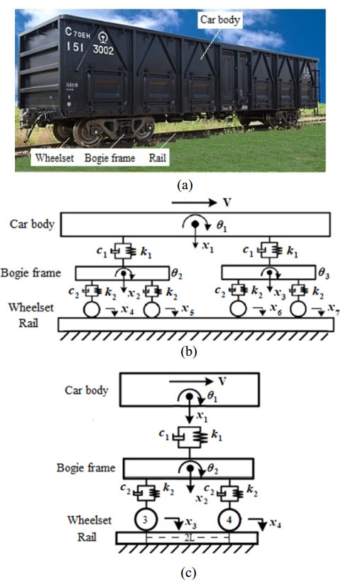
Traditional vertical vibration models of rail vehicle usually have high degrees of freedom, which affects the efficiency of numerical simulation. Regardless of the coupling effect between the vehicle and rail, a six degree of freedom (6DOF) quarter model with vertical displacement and rotation angle is selected as the dynamic model. This accomplished by comparing the simulation results of half model and quarter model of the railway freight wagon, and the vertical vibration characteristics of the railway freight wagon when the wagon speed is changed. To further illustrate the nonlinear vibration characteristics and evolution laws of the car body and bogie frame of the freight wagon, the bifurcation diagrams, maximum Lyapunov exponent curves, axis trajectory curves, phase plane plots, Poincaré sections, and amplitude spectras are drawn and adopted to research the dynamic responses. The simulations reveal the complex vibration behavior such as periodic, quasi-periodic, multi-periodic, and chaotic motion. Some research results can help the industry to better design the speed limits of such railway freight wagons, and deeply understand or utilize the vertical vibration law of railway freight wagon in future research.
Citation: Juping Yang, Junguo Wang, Yongxiang Zhao. Simulation of nonlinear characteristics of vertical vibration of railway freight wagon varying with train speed[J]. Electronic Research Archive, 2022, 30(12): 4382-4400. doi: 10.3934/era.2022222
Traditional vertical vibration models of rail vehicle usually have high degrees of freedom, which affects the efficiency of numerical simulation. Regardless of the coupling effect between the vehicle and rail, a six degree of freedom (6DOF) quarter model with vertical displacement and rotation angle is selected as the dynamic model. This accomplished by comparing the simulation results of half model and quarter model of the railway freight wagon, and the vertical vibration characteristics of the railway freight wagon when the wagon speed is changed. To further illustrate the nonlinear vibration characteristics and evolution laws of the car body and bogie frame of the freight wagon, the bifurcation diagrams, maximum Lyapunov exponent curves, axis trajectory curves, phase plane plots, Poincaré sections, and amplitude spectras are drawn and adopted to research the dynamic responses. The simulations reveal the complex vibration behavior such as periodic, quasi-periodic, multi-periodic, and chaotic motion. Some research results can help the industry to better design the speed limits of such railway freight wagons, and deeply understand or utilize the vertical vibration law of railway freight wagon in future research.

| [1] |
S. Bruni, J. P. Meijaard, G. Rill, A. L. Schwab, State-of-the-art and challenges of railway and road vehicle dynamics with multibody dynamics approaches, Multibody Syst. Dyn., 49 (2020), 1–32. https://doi.org/10.1007/s11044-020-09735-z doi: 10.1007/s11044-020-09735-z

|
| [2] |
S. D. Iwnicki, S. Stichel, A. Orlova, M. Hecht, Dynamics of railway freight vehicles, Veh. Syst. Dyn., 53 (2015), 995–1033. https://doi.org/10.1016/j.jsv.2018.12.033 doi: 10.1016/j.jsv.2018.12.033
|
| [3] |
C. R. Ding, X. Y. Peng, Q. S. Wang, Research on dynamic characterization of railway freight car under wheel flat condition (in Chinese), Mech. Sci. Tech. Aero. Eng., 40 (2021), 1279–1284. https://doi.org/10.13433/j.cnki.1003-8728.20200205 doi: 10.13433/j.cnki.1003-8728.20200205
|
| [4] |
B. Esteban, S. Maksym, S. C. Colin, Wheel flat detectability for Y25 railway freight wagon using vehicle component acceleration signals, Veh. Syst. Dyn., 58 (2020), 1893–1913. https://doi.org/10.1080/00423114.2019.1657155 doi: 10.1080/00423114.2019.1657155
|
| [5] |
M. Naeimi, J. A. Zakeri, M. Shadfar, M. Esmaeili, 3D dynamic model of the railway wagon to obtain the wheel-rail forces under track irregularities, Proc. Inst. Mech. Eng. Part F: J. Multibody Dyn., 229 (2015), 357–369. https://doi.org/10.1177/1464419314566833 doi: 10.1177/1464419314566833
|
| [6] |
E. D. Gialleonardo, S. Bruni, H. True, Analysis of the nonlinear dynamics of a 2-axle freight wagon in curves, Veh. Syst. Dyn., 52 (2014), 125–141. https://doi.org/10.1080/00423114.2013.863363 doi: 10.1080/00423114.2013.863363
|
| [7] |
S. Q. Sui, K. Y. Wang, L. Ling, Z. G. Chen, Effect of wheel diameter difference on tread wear of freight wagons, Eng. Fail. Anal., 127 (2021), 1873–1961. https://doi.org/10.1016/j.engfailanal.2021.105501 doi: 10.1016/j.engfailanal.2021.105501
|
| [8] | H. True, R. Asmund, The dynamics of a railway freight wagon wheelset with dry friction damping, Veh. Syst. Dyn., 38 (2002), 149–163. |
| [9] |
R. M. Zou, S. H. Luo, W. H. Ma, Simulation analysis on the coupler behaviour and its influence on the braking safety of locomotive, Veh. Syst. Dyn., 56 (2018), 1747–1767. https://doi.org/10.1080/00423114.2018.1435893 doi: 10.1080/00423114.2018.1435893
|
| [10] |
M. Hoffmann, On the dynamics of European two-axle railway freight wagons, Nonlinear Dyn., 52 (2008), 301–311. https://doi.org/10.1007/s11071-007-9279-1 doi: 10.1007/s11071-007-9279-1
|
| [11] |
Q. Wu, C. Cole, M. Spiryagin, Train braking simulation with wheel-rail adhesion model, Veh. Syst. Dyn., 58 (2020), 1226–1241. https://doi.org/10.1080/00423114.2019.1645342 doi: 10.1080/00423114.2019.1645342
|
| [12] |
J. Bian, Y. T. Gu, H. M. Martin, A dynamic wheel-rail impact analysis of railway track under wheel flat by finite element analysis, Veh. Syst. Dyn., 51 (2013), 784–797. https://doi.org/10.1080/00423114.2013.774031 doi: 10.1080/00423114.2013.774031
|
| [13] |
G. E. Di, G. Cazzulani, S. Melzi, F. Braghin, The effect of train composition on the running safety of low-flatcar wagons in braking and curving manoeuvres, Proc. Inst. Mech. Eng. Part F: J. Rail Rapid Transit., 231 (2017), 666–677. https://doi.org/10.1177/0954409716636923 doi: 10.1177/0954409716636923
|
| [14] |
H. C. Zhou, J. Zhang, M. Hecht, Three-dimensional derailment analysis of crashed freight trains, Veh. Syst. Dyn., 52 (2014), 341–361. https://doi.org/10.1080/00423114.2014.881512 doi: 10.1080/00423114.2014.881512
|
| [15] |
L. Xu, X. M. Chen, X. W. Li, X. L. He, Development of a railway wagon-track interaction model: case studies on excited tracks, Mech. Syst. Signal Pr., 100 (2018), 877–898. https://doi.org/10.1016/j.ymssp.2017.08.008 doi: 10.1016/j.ymssp.2017.08.008
|
| [16] |
D. Zhang, D. B. Clarke, Y. Peng, H. Gao, C. J. Dong, Effect of the combined centre of gravity on the running safety of freight wagons, Veh. Syst. Dyn., 57 (2019), 1271–1286. https://doi.org/10.1080/00423114.2018.1494841 doi: 10.1080/00423114.2018.1494841
|
| [17] |
S. Jozef, J. Marek, W. Dariusz, Modelling the longitudinal dynamics of long freight trains on broad gauge metallurgical railway line, Procedia Eng., 192 (2017), 840–844. https://doi.org/10.1016/j.proeng.2017.06.145 doi: 10.1016/j.proeng.2017.06.145
|
| [18] |
Q. Wu, C. Cole, M. Spiryagin, Y. Q. Sun, A review of dynamics modelling of friction wedge suspensions, Veh. Syst. Dyn., 52 (2014), 1389–1415. http://dx.doi.org/10.1080/00423114.2014.943249 doi: 10.1080/00423114.2014.943249
|
| [19] |
Q. Wu, Y, Sun, M. Spiryagin, C. Cole, Methodology to optimize wedge suspensions of three-piece bogie of railway vehicles, J. Vib. Control., 24 (2018), 565–581. https://doi.org/10.1177/1077546316645698 doi: 10.1177/1077546316645698
|
| [20] |
V. V. Krishna, M. Berg, S. Stichel, Tolerable longitudinal forces for freight trains in tight S-curves using three-dimensional multi-body simulations, Proc. Inst. Mech. Eng. Part F: J. Rail Rapid Transit., 234 (2020), 454–467. https://doi.org/10.1177/0954409719841794 doi: 10.1177/0954409719841794
|
| [21] |
R. A. Oprea, C. Cruceanu, M. A. Spiroiu, Alternative friction models for braking train dynamics, Veh. Syst. Dyn., 51 (2013), 460–480. https://doi.org/10.1080/00423114.2012.744459 doi: 10.1080/00423114.2012.744459
|
| [22] |
J. Matej, A new mathematical model of the behaviour of a four-axle freight wagon with UIC single-link suspension, Proc. Inst. Mech. Eng. Part F: J. Rail Rapid Transit., 225 (2011), 637–647. https://doi.org/10.1177/0954409711398173 doi: 10.1177/0954409711398173
|
| [23] |
R. Serajian, S. Mohammadi, A. Nasr, Influence of train length on in-train longitudinal forces during brake application, Veh. Syst. Dyn., 57 (2019), 192–206. https://doi.org/10.1080/00423114.2018.1456667 doi: 10.1080/00423114.2018.1456667
|
| [24] |
M. R. Ghazavi, M. Taki, Dynamic simulations of the freight three-piece bogie motion in curve, Veh. Syst. Dyn., 46 (2008), 955–973. https://doi.org/10.1080/00423110701730737 doi: 10.1080/00423110701730737
|
| [25] |
G. Deng, Y. Peng, C. Yan, B. Wen, Running safety evaluation of a 350 km/h high-speed freight train negotiating a curve based on the arbitrary Lagrangian-Eulerian method, Proc. Inst. Mech. Eng. Part F: J. Rail Rapid Transit., 235 (2021), 1143–1157. https://doi.org/10.1177/0954409720986283 doi: 10.1177/0954409720986283
|
| [26] |
W. M. Zhai, Q. C. Wang, Z. W. Lu, X. S. Wu, Dynamic effects of vehicles on tracks in the case of raising train speeds, Proc. Inst. Mech. Eng. Part F: J. Rail Rapid Transit., 215 (2001), 125–135. https://doi.org/10.1243/0954409011531459 doi: 10.1243/0954409011531459
|
| [27] |
M. A. Rezvani, A. Mazraeh, Dynamics and stability analysis of a freight wagon subjective to the railway track and wheelset operational conditions, J. Mec. Theor. Appl., 61 (2017), 22–34. https://doi.org/10.1016/j.euromechsol.2016.08.011 doi: 10.1016/j.euromechsol.2016.08.011
|
| [28] |
R. Kovalev, N. Lysikov, G. Mikheev, D. Pogorelov, V. Simonov, V. Yazykov, et al., Freight car models and their computer-aided dynamic analysis, Multibody Syst Dyn., 22 (2009), 399–423. https://doi.org/10.1007/s11044-009-9170-6 doi: 10.1007/s11044-009-9170-6
|
| [29] |
S. Stichel, Limit cycle behaviour and chaotic motions of two axle freight wagons with friction damping, Multibody Syst Dyn, 8 (2002), 243–255. https://doi.org/10.1023/A:1020990128895 doi: 10.1023/A:1020990128895
|
| [30] |
H. Mark, T. Hans, The dynamics of European two-axle railway freight wagons with UIC standard suspension, Veh. Syst. Dyn., 46 (2019), 225–236. https://doi.org/10.1080/00423110801935848 doi: 10.1080/00423110801935848
|
| [31] |
J. Zhang, Q. Gao, S. J. Tan, W. X. Zhong, A precise integration method for solving coupled vehicle-track dynamics with nonlinear wheel-rail contact, J. Sound Vib., 331 (2012), 4763–4773. https://doi.org/10.1016/j.jsv.2012.05.033 doi: 10.1016/j.jsv.2012.05.033
|


Figures(10) / Tables(1)
Juping Yang, Junguo Wang, Yongxiang Zhao. Simulation of nonlinear characteristics of vertical vibration of railway freight wagon varying with train speed[J]. Electronic Research Archive, 2022, 30(12): 4382-4400. doi: 10.3934/era.2022222


 DownLoad: