Interconnected Microgrid (IMG) networks have been suggested as the best to build electrical networks in remote villages far from the main electricity grid by interconnecting the nearby distributed energy resources (DERs) through power electronic converters. Interconnecting different DERs results in voltage deviation with unequal power-sharing, while voltage performance is a significant challenge. The control strategies for these converters are essential in the operational stability of any IMG network under study. In this paper, we propose an improved droop control method aiming to manage the power flow among the IMGs by maintaining the constant desired voltages in the network with minimum voltage deviation, resulting in the minimization of power losses. We found that the minimum voltage deviation at the load side (converter-3) was between 0.58 and 0.56 V, while the voltage deviation for both converter-1 and converter-2 remained below 0.5 V. This leads to efficient voltage regulation, resulting in the stability of an IMG network. To verify the feasibility of this method, MATLAB/SIMULINK has been used.
Citation: Pascal Hategekimana, Adrià Junyent-Ferré, Etienne Ntagwirumugara, Joan Marc Rodriguez Bernuz. Improved methods for controlling interconnected DC microgrids in rural villages[J]. AIMS Energy, 2024, 12(1): 214-234. doi: 10.3934/energy.2024010
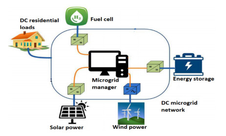
Interconnected Microgrid (IMG) networks have been suggested as the best to build electrical networks in remote villages far from the main electricity grid by interconnecting the nearby distributed energy resources (DERs) through power electronic converters. Interconnecting different DERs results in voltage deviation with unequal power-sharing, while voltage performance is a significant challenge. The control strategies for these converters are essential in the operational stability of any IMG network under study. In this paper, we propose an improved droop control method aiming to manage the power flow among the IMGs by maintaining the constant desired voltages in the network with minimum voltage deviation, resulting in the minimization of power losses. We found that the minimum voltage deviation at the load side (converter-3) was between 0.58 and 0.56 V, while the voltage deviation for both converter-1 and converter-2 remained below 0.5 V. This leads to efficient voltage regulation, resulting in the stability of an IMG network. To verify the feasibility of this method, MATLAB/SIMULINK has been used.

| [1] |
Dou CX, Zhang ZQ, Yue D, et al. (2017) Improved droop control based on virtual impedance and virtual power source in low-voltage microgrid. IET Gener Transm Distrib 11: 1046–1054. https://doi.org/10.1049/iet-gtd.2016.1492 doi: 10.1049/iet-gtd.2016.1492

|
| [2] | Rodriguez-Bernuz JM, Junyent-Ferré A, Xiang X (2020) Optimal droop offset adjustments for accurate energy trading in rural DC mini-grid clusters. 2020 International Conference on Smart Grids and Energy Systems (SGES), Perth, Australia, 453–458. https://doi.org/10.1109/SGES51519.2020.00086 |
| [3] | Hategekimana P, Junyent-Ferré A, Rodriguez-Bernuz JM, et al. (2020) Assessment of feasible DC microgrid network topologies for rural electrification in Rwanda: Studying the kagoma village. 2020 International Conference on Smart Grids and Energy Systems (SGES), Perth, Australia, 854–859. https://doi.org/10.1109/SGES51519.2020.00157 |
| [4] |
Anand Abhishek SK, Aashish R, Sachin D, et al. (2020) Review of hierarchical control strategies for DC microgrid. IET Renewable Power Gener 14: 1631–1640. https://doi.org/10.1049/iet-rpg.2019.1136 doi: 10.1049/iet-rpg.2019.1136
|
| [5] | Mohamed MA, Abdullah H, Al-sumaiti A, et al. (2020) Towards energy management negotiation between distributed AC/DC networks. https://doi.org/10.1109/ACCESS.2020.3040503 |
| [6] |
Gorijeevaram Reddy PK, Dasarathan S, Krishnasamy V (2021) Investigation of adaptive droop control applied to low-voltage DC microgrid. Energies 14: 1–20. https://doi.org/10.3390/en14175356 doi: 10.3390/en14175356
|
| [7] |
Hai NT, Kim KH (2016) An adaptive virtual impedance based droop control scheme for parallel inverter operation in low voltage microgrid. Int J Power Electron Drive Syst 7: 1309–1319. https://doi.org/10.11591/ijpeds.v7i4.pp1309-1319 doi: 10.11591/ijpeds.v7i4.pp1309-1319
|
| [8] | Kala B, Raju A, Varun J, et al. (2018) Circulating current minimization in low-voltage DC microgrid based on droop control strategy. Int J Res Anal Rev 5: 577–582. |
| [9] | Rawaa A (2022) Voltage control and power sharing in DC microgrids (DCMG). CASE West Reserv Univ, 1–69. |
| [10] |
Rashad M, Raoof U, Siddique N, et al. (2021) Mitigation of circulating currents for parallel connected sources in a standalone DC microgrid. Eng Proc 12: 4–9. https://doi.org/10.3390/engproc2021012031 doi: 10.3390/engproc2021012031
|
| [11] |
Tameemi Z, Lie T, Foo G, et al. (2022) Optimal coordinated control strategy of clustered DC microgrids under load-generation uncertainties based on GWO. Electronics 11: 1244. https://doi.org/10.3390/electronics11081244 doi: 10.3390/electronics11081244
|
| [12] |
Tameemi Z, Lie T, Foo G, et al. (2021) Control strategies of DC microgrids cluster: A comprehensive review. Energies 14: 7569. https://doi.org/10.3390/en14227569 doi: 10.3390/en14227569
|
| [13] |
Nascimento R, Ramos F, Pinheiro A, et al. (2022) Case study of backup application with energy storage in microgrids. Energies 15: 9514. https://doi.org/10.3390/en15249514 doi: 10.3390/en15249514
|
| [14] |
Lexuan M, Qobad S, Giancarlo F, et al. (2017) Review on control of DC microgrids and multiple microgrid clusters. IEEE J Emerg Sel Top Power Electron 5: 928–948. https://doi.org/10.1109/JESTPE.2017.2690219 doi: 10.1109/JESTPE.2017.2690219
|
| [15] |
Yang H, Zhang Y, Wang P (2021) Flexible interconnection of DC microgrid cluster based on isolated bidirectional DC-DC converter. Syst Sci Control Eng 9: 641–650. https://doi.org/10.1080/21642583.2021.1975322 doi: 10.1080/21642583.2021.1975322
|
| [16] |
Fathi M, Bevrani H (2017) Regulating power management in interconnected microgrids. J Renewable Sustainable Energy 9: 055502. https://doi.org/10.1063/1.5003003 doi: 10.1063/1.5003003
|
| [17] |
Islam M, Yang F, Amin M (2021) Control and optimisation of networked microgrids: A review. IET Renewable Power Gener 15: 1133–1148. https://doi.org/10.1049/rpg2.12111 doi: 10.1049/rpg2.12111
|
| [18] |
Han Y, Pu Y, Li Q, et al. (2019) Coordinated power control with virtual inertia for fuel cell-based DC microgrids cluster. Int J Hydrogen Energy 44: 25207–25220. https://doi.org/10.1016/j.ijhydene.2019.06.128 doi: 10.1016/j.ijhydene.2019.06.128
|
| [19] |
Ullah S, Haidar A, Hoole P, et al. (2020) The current state of distributed renewable generation, challenges of interconnection and opportunities for energy conversion based DC microgrids. J Clean Prod 273: 122777. https://doi.org/10.1016/j.jclepro.2020.122777 doi: 10.1016/j.jclepro.2020.122777
|
| [20] |
Hategekimana P, Junyent-Ferré A, Rodriguez-Bernuz JM, et al. (2022) Fault detecting and isolating schemes in a low-voltage DC microgrid network from a remote village. Energies 15: 1–16. https://doi.org/10.3390/en15124460 doi: 10.3390/en15124460
|
| [21] |
Chen J, Alnowibet K, Annuk A, et al. (2021) An effective distributed approach based machine learning for energy negotiation in networked microgrids. Energy Strateg Rev 38: 100760. https://doi.org/10.1016/j.esr.2021.100760 doi: 10.1016/j.esr.2021.100760
|
| [22] | Tepe IF (2022) A review of control strategies and metaheuristic algorithms used in DC microgrids. Int J Renewable Energy Res 12: 799–818. |
| [23] | Peyghami S, Mokhtari H, Blaabjerg F (2017) Hierarchical power sharing control in DC microgrids. Microgrid, 63–100. https://doi.org/10.1016/B978-0-08-101753-1.00003-6 |
| [24] |
Li Z, Shahidehpour M, Aminifar F, et al. (2017) Networked microgrids for enhancing the power system resilience. Proc IEEE 105: 1289–1310. https://doi.org/10.1109/JPROC.2017.2685558 doi: 10.1109/JPROC.2017.2685558
|
| [25] |
Lu X, Guerrero JM, Sun K, et al. (2014) An improved droop control method for DC microgrids based on low bandwidth communication with dc bus voltage restoration and enhanced current sharing accuracy. IEEE Trans Power Electron 29: 1800–1812. https://doi.org/10.1109/TPEL.2013.2266419 doi: 10.1109/TPEL.2013.2266419
|
| [26] | Zammit D (2022) Control of DC microgrids for distributed generation including energy storage. Univ Malta (PhD thesis), 1–255. |
| [27] |
Aluko A, Swanson A, Jarvis L (2022) Modeling and stability analysis of distributed secondary control scheme for stand-alone DC microgrid applications. Energies 15: 1–18. https://doi.org/10.3390/en15155411 doi: 10.3390/en15155411
|
| [28] |
Li B, Li Q, Wang Y, et al. (2020) A novel method to determine droop coefficients of DC voltage control for VSC-MTDC system. IEEE Trans Power Deliv 35: 2196–2211. https://doi.org/10.1109/TPWRD.2019.2963447 doi: 10.1109/TPWRD.2019.2963447
|
| [29] | Siva Sankar BRKK, Valli VS (2020) A droop control strategy for minimization of circulating current in low-voltage DC micro grid. Pramana Res J 10: 145–153. |
| [30] |
Zhang L, Chen K, Chi S, et al. (2019) The hierarchical control algorithm for DC microgrid. Energies 12: 2995. https://doi.org/10.3390/en12152995 doi: 10.3390/en12152995
|
| [31] |
Mokhtar M, Marei MI, El-sattar AA, et al. (2018) Improved current sharing techniques for DC microgrids. Electr Power Components Syst 46: 757–767. https://doi.org/10.1080/15325008.2018.1512176 doi: 10.1080/15325008.2018.1512176
|
| [32] | Panda M, Bhaskar DV, Maity T (2022) A fuzzy-based coordinated power management strategy for voltage regulation and state-of-charge balancing in multiple subgrid-based DC microgrid. Int Trans Electr Energy Syst 2022. https://doi.org/10.1155/2022/1288985 |
| [33] |
Cucuzzella ASM, Trip S, De Persis C, et al. (2019) A robust consensus algorithm for current sharing and voltage regulation in DC microgrids. IEEE Trans Control Syst Technol 27: 1583–1595. https://doi.org/10.1109/TCST.2018.2834878 doi: 10.1109/TCST.2018.2834878
|


Figures(19) / Tables(1)

Pascal Hategekimana, Adrià Junyent-Ferré, Etienne Ntagwirumugara, Joan Marc Rodriguez Bernuz. Improved methods for controlling interconnected DC microgrids in rural villages[J]. AIMS Energy, 2024, 12(1): 214-234. doi: 10.3934/energy.2024010


 DownLoad: