Processing math: 100%
Research article Special Issues

Investigation and geotechnical characterization of Perniö clay, Finland

  • Understanding the behavior of soft sensitive clays is a key aspect of geotechnical design, especially in those regions where constructions are planned in marine clay areas. In Finland, one of the major geotechnical issues is the stability and deformation of the railway embankments located on soft soil deposits. The Tampere University of Technology (TUT) and the Finnish Transport Agency (FTA) have been carrying out a research project aiming to a better understanding of strength and deformation properties of Finnish soft clays. As a part of this project, a detailed site investigation was conducted at Perniö site in Western Finland. This paper presents the details of the geotechnical investigation, including field testing, sampling operations, and the laboratory testing program. In particular, an open drive tube sampler with 132 mm diameter, designed at TUT, was used to collect high quality samples. For comparison, samples were also taken using the conventional piston samplers and Sherbrooke Mini-block sampler. Field testing included piezocone, vane shear, and seismic piezocone. Laboratory testing consisted of index, consolidation, triaxial and simple shear tests. A comprehensive study of all these data is presented in a framework to describe Perniö soft clay.

    Citation: Bruno Di Buò, Marco D’Ignazio, Juha Selänpää, Markus Haikola, Tim Länsivaara, Marta Di Sante. Investigation and geotechnical characterization of Perniö clay, Finland[J]. AIMS Geosciences, 2019, 5(3): 591-616. doi: 10.3934/geosci.2019.3.591

    Related Papers:

    [1] Robert Radaszewski, Jędrzej Wierzbicki . Characterization and engineering properties of AMU Morasko soft clay. AIMS Geosciences, 2019, 5(2): 235-264. doi: 10.3934/geosci.2019.2.235
    [2] Paul W. Mayne, Ethan Cargill, Bruce Miller . Geotechnical characteristics of sensitive Leda clay at Canada test site in Gloucester, Ontario. AIMS Geosciences, 2019, 5(3): 390-411. doi: 10.3934/geosci.2019.3.390
    [3] Don J. DeGroot, Melissa E. Landon, Steven E. Poirier . Geology and engineering properties of sensitive Boston Blue Clay at Newbury, Massachusetts. AIMS Geosciences, 2019, 5(3): 412-447. doi: 10.3934/geosci.2019.3.412
    [4] Aleksander S. Gundersen, Ragnhild C. Hansen, Tom Lunne, Jean-Sebastien L’Heureux, Stein O. Strandvik . Characterization and engineering properties of the NGTS Onsøy soft clay site. AIMS Geosciences, 2019, 5(3): 665-703. doi: 10.3934/geosci.2019.3.665
    [5] Marco D'Ignazio, Tom Lunne, Knut. H. Andersen, Shaoli Yang, Bruno Di Buò, Tim Länsivaara . Estimation of preconsolidation stress of clays from piezocone by means of high-quality calibration data. AIMS Geosciences, 2019, 5(2): 104-116. doi: 10.3934/geosci.2019.2.104
    [6] Ariane Locat, Pascal Locat, Hubert Michaud, Kevin Hébert, Serge Leroueil, Denis Demers . Geotechnical characterization of the Saint-Jude clay, Quebec, Canada. AIMS Geosciences, 2019, 5(2): 273-302. doi: 10.3934/geosci.2019.2.273
    [7] Don J. DeGroot, Tom Lunne, Ravindra Ghanekar, Siren Knudsen, Cody D. Jones, Tor Inge Yetginer-Tjelta . Engineering properties of low to medium overconsolidation ratio offshore clays. AIMS Geosciences, 2019, 5(3): 535-567. doi: 10.3934/geosci.2019.3.535
    [8] Tonje Eide Helle, Per Aagaard, Steinar Nordal, Michael Long, Sara Bazin . A geochemical, mineralogical and geotechnical characterization of the low plastic, highly sensitive glaciomarine clay at Dragvoll, Norway. AIMS Geosciences, 2019, 5(4): 704-722. doi: 10.3934/geosci.2019.4.704
    [9] Jean-Sébastien L'Heureux, Anders Lindgård, Arnfinn Emdal . The Tiller-Flotten research site: Geotechnical characterization of a very sensitive clay deposit. AIMS Geosciences, 2019, 5(4): 831-867. doi: 10.3934/geosci.2019.4.831
    [10] Solve Hov, David Gaharia . Geotechnical characterization of index and deformation properties of Stockholm clays. AIMS Geosciences, 2023, 9(2): 258-284. doi: 10.3934/geosci.2023015
  • Understanding the behavior of soft sensitive clays is a key aspect of geotechnical design, especially in those regions where constructions are planned in marine clay areas. In Finland, one of the major geotechnical issues is the stability and deformation of the railway embankments located on soft soil deposits. The Tampere University of Technology (TUT) and the Finnish Transport Agency (FTA) have been carrying out a research project aiming to a better understanding of strength and deformation properties of Finnish soft clays. As a part of this project, a detailed site investigation was conducted at Perniö site in Western Finland. This paper presents the details of the geotechnical investigation, including field testing, sampling operations, and the laboratory testing program. In particular, an open drive tube sampler with 132 mm diameter, designed at TUT, was used to collect high quality samples. For comparison, samples were also taken using the conventional piston samplers and Sherbrooke Mini-block sampler. Field testing included piezocone, vane shear, and seismic piezocone. Laboratory testing consisted of index, consolidation, triaxial and simple shear tests. A comprehensive study of all these data is presented in a framework to describe Perniö soft clay.


    In Scandinavian countries, USA, and Canada, the geotechnical design is often challenging because of the presence of soft sensitive clays. These soils are known for their potential for large landslides, thus representing a serious risk in terms of human lives loss and damages to infrastructures. In Finland, a major geotechnical issue involves the stability and deformation of railway embankments built on soft clays. In relation to this, the Tampere University of Technology (TUT) and the Finnish Transport Agency (FTA) have been carrying out a number of research projects aiming to improve the commonly used stability calculation methods and the quality of ground investigation data. These studies revealed that the traditional field investigation tools (e.g., Field Vane test) and sampling equipment (e.g. ST:1 50 piston sampler) commonly employed in Finland often suffer from inaccuracy [1,2]. For this reason, in 2014, a research project named "Fincone" was started, with the aim to improve the quality of field and laboratory investigation. Among others, the Perniö soft clay site was included as part of the Fincone project.

    The soil conditions at Perniö consist mainly of very soft saturated sensitive clay, with apparent overconsolidation due to aging effects. The Perniö site worked as a benchmark site for several research studies on Finnish clays. As an example, a full-scale railway embankment failure test was conducted in 2009 in order to collect extensive monitoring data and test the reliability of the stability calculation methods [3,4,5,6,7,8,9]. The field investigation at Perniö was conducted by using the piezocone test (CPTu) and the Field Vane (FV) test, while the laboratory tests were carried out on high quality undisturbed samples. Various sampling apparatuses have been tested, including the traditional piston samplers, an innovative Laval-type tube sampler [10] and the Sherbrooke Mini-block sampler [11]. This paper discusses in detail the results of the investigation, with particular emphasis on the performance of the different sampling apparatuses, the in-situ and laboratory testing methods and the evaluation of strength and deformation properties of Perniö clay.

    Fine-grained soil sediments in Finland originated during the retreat of the continental Fennoscandian ice sheet during late Weichselian (13,000 cal BP). The Baltic Ice Lake originated from the accumulation of freshwater deriving from the melting of the North glacier. This area has gone through four environmental stages known as the Baltic Ice Lake, Yoldia Sea, Ancylus Lake, and Litorina Sea (Figure 1). The initial sedimentation took place in the close proximity of the continental ice sheet, in fresh water environment (Baltic Ice Lake). At this stage, the lake did not mix with the seawater from the west because the ground on the whole depression rose faster than the sea level did. However, the connection between the Baltic Lake and the Atlantic Ocean occurred 11,500 years ago when the glacier front retreated to the North. Consequently, the water level of the Baltic Sea decreased rapidly reaching the sea level. From this point on, the Baltic water body turned into the Yoldia Sea. At the early stage, the depositional environment was still characterized by fresh water due to the heavy water flow from the continental ice sheet. However, the salinity started to increase 200 years after the connection with the ocean opened, thus creating a brackish depositional environment. Afterwards, the Yoldia Sea turned into Ancylus Lake due to isostatic uplift of the ground, which closed the existing connection with the Atlantic Ocean. This stage lasted until 10,000 years before present when a new connection with the Atlantic Ocean was established due to the rise of the Ancylus water level. During this stage, known as Litorina Sea, the salinity increased even though the continuous land rise made the connection with the ocean more shallow allowing less salt water to enter it. The particular geological formation and post-depositional processes experienced by the Finnish soil deposits lead to different geotechnical properties compared to other Scandinavian clays. As an example, Finnish clays are characterized by higher water content, clay content and plasticity compared to Norwegian clays [12]. Moreover, the salt content in the pore water fluid is generally lower than 2 g/l [13].

    Figure 1.  Development of the Baltic Sea during the late glacial and postglacial [14].

    The topography and topsoil formation of Perniö clay is shown in Figure 2. The site is located in an old river valley originated between bedrock hills. Combining the soil stratigraphy properties and the topographic map, it is possible to identify the different stages of the Baltic Sea formation. The sandy and silty layers located below 9 m depth probably originated during the Baltic Ice Lake while the clayey layer located between 5.5 m and 9 m depth belong to the Yoldia Sea phase. The 2 m thick layer above the Yoldia sediments consists probably of Ancylus Lake sediments, as suggested by the slightly lower clay and organic content. The uppermost clay layer located immediately below the dry crust originated during the Litorina Sea stage as indicated by the high organic and water content. Finally, the dry crust presents different properties compared to the other layers because of weathering, chemical processes and frost action.

    Figure 2.  Topography and topsoil formations of Perniö site [13].

    Microstructural and chemical investigations were performed by means of SEM observations carried out with Philips XL20 Microscope (W filament, detector Everhart-Thornley for secondary electrons, solid state detector for backscattered electrons, maximum voltage: 30 kV), after air dewatering of samples and their gilding by means of Emitech K550 sputter coater. Energy dispersive X-Ray spectroscopy (EDS) was further performed by 20-30 kV voltage with the aim to identify the main chemical compounds in the soil. They are listed in Table 1.

    Table 1.  Summary of chemical compounds, Perniö (z = 4.5 m).
    Element Mass (%)
    Silicon 52
    Calcium 2
    Aluminum 16
    Iron 14
    Potassium 7.5
    Magnesium 3.5
    Sodium 2
    Other compounds 3

     | Show Table
    DownLoad: CSV

    The mineralogical composition has been evaluated from X-ray diffraction analysis (XRD) by means of a Philips diffractometer (PW1730 X-ray generator, PW 1050/70 goniometer and CuKα radiation). The sample taken at 4.5 m depth was preliminary treated to remove the organic fraction and carbonates by adding hydrogen peroxide and hydrochloric acid. Then, the clay fraction was isolated by using the Andreasen pipette. The analysis of the test results (Figure 3) revealed the presence of Chlorite, Mica and Quartz as main components.

    Figure 3.  X-ray diffraction analysis (XRD), Perniö (z = 4.5 m).

    Micrographs of the soil are shown in Figure 4. It is possible to notice that Mica (Figure 4a) and rosette-like structures of Chlorite (ChL, in Figure 4b) are widely distributed across the sample. Moreover, diatoms are systematically detected in the observed samples (marked with letter D in Figure 4c and 4d). They are centric diatoms typically present in freshwater environments. Their presence is due to the depositional history of Perniö clay and, in particular, associated with the Baltic Ice Lake phase during Pleistocene.

    Figure 4.  Micrographs of Perniö clay (z = 4.5 m).

    The geotechnical investigation at Perniö site included an extensive field and laboratory testing program. In this section, details of the apparatuses, testing methods and relevant results are presented.

    The field investigation has been carried out using the Field Vane (FV) and CPTu tests. In Finland, the FV test is the traditional investigation tool to evaluate the undrained shear strength. However, recent studies conducted at TUT revealed that this test is affected by many sources of uncertainty coming from some features of the different apparatuses as well as testing procedures [2]. In particular, it has been observed that relying solely on the slip coupling without using a casing, may underestimate the undrained shear strength of soft clays. For this reason, an innovative electrical downhole apparatus equipped with casing has been employed at Perniö site. The vane consists of a four blades fixed at 90° with a length/width ratio of 2 (75 mm diameter, 150 mm length and 2 mm thickness) placed into a casing. The drive unit and torque sensor are located into a robust case right above the vane (downhole configuration). The test is conducted by pushing the entire apparatus to the desired depth, inserting the vane into the undisturbed soil and applying a rate of rotation of 0.1°/s to ensure undrained conditions. The undrained shear strength is evaluated from the measured torque moment by taking into account the vane dimensions and shape. Figure 5 shows the results obtained at Perniö site. Tests performed on three nearby verticals show good repeatability. However, some scatter is observed at shallow depths, probably due to the vicinity of the dry crust layer, as proper predrilling was not used. The uncorrected shear strength increases from 5 kPa at 2 m depth to 15 kPa at 7 m depth. The peak strength occurs at ≈ 5° rotation.

    Figure 5.  (a) Uncorrected undrained shear strength vs depth with downhole FV; (b) Results of FV tests performed at 2.10 m depth [2].

    The CPTu equipment employed at Perniö site includes a pushing system installed on a tracked CPT truck, a high capacity and low capacity (or sensitive) cone penetrometers and additional plug-in modules. Technical specifications of the cone penetrometers employed are summarized in Table 2.

    Table 2.  Technical specifications of cone penetrometers.
    Parameter Nominal range (MPa)
    Standard Sensitive
    cone tip resistance (qc) 75 7.5
    sleeve friction (fs) 1 0.15
    pore pressure (u2) 2 10

     | Show Table
    DownLoad: CSV

    Details of the apparatus and testing procedures are discussed in [1]. The penetrometer consists of a standard 60° cone, with 10 cm2 base area and a 150 cm2 lateral friction sleeve area. The porewater pressure is measured above the cone tip (u2). The porous stone is saturated with silicon oil by means of a vacuum device. In order to avoid the desaturation of the porous filter, an initial pre-drilling has been made through the dry crust layer. Tests were carried out by pushing the probe at 20 mm/s penetration rate according to the European Standards [15]. Additional information have been obtained by using the seismic and resistivity modules plugged into the CPTu probe.

    The seismic module consists of a single element receiver and three accelerometers for the recording of the left and right shear waves as well as compression waves. The seismic test is performed at one-meter interval while the cone penetration is stopped. Shear and compression waves are generated by striking a metal plate rigidly placed at the ground surface at 2.4 m distance from the CPT vertical. The metal plate is hit with a hammer in two opposite directions in order to generate a "right" and "left" polarized shear waves, and in the vertical direction to generate compression waves. To ensure that the seismic measurements are not affected by any background noise, the CPT rig is stopped during the test execution. The shear wave velocity vs is calculated by dividing the incremental traveling distance to the geophone by the incremental arriving time between successive recorded shear waves. In particular, the travel time is measured by using an electronic trigged mounted on the metal plate.

    The conductivity module consists of four electrode rings isolated from each other by ceramic components. By generating a known current between the outer electrodes which causes a voltage difference across the inner electrodes, it allows to evaluate the soil conductivity.

    Figure 6 shows the stratigraphy at Perniö site, the corrected cone tip resistance (qt), the sleeve friction (fs), the pore water pressure (u2), the friction ratio (Rf = fs/qt), the normalized pore pressure ratio [Bq=(u2u0)/(qtσv0)] and the additional seismic and resistivity measurements. Different soundings were performed to investigate the accuracy and repeatability of the piezocone tests. Scatter in the measurement is observed in the uppermost part of the deposit, right below the dry crust, as a consequence of (ⅰ) lower accuracy of the high capacity cone and (ⅱ) the natural soil variability in the shallow layer. However, below 3 m depth, tests show very good repeatability between the different nearby verticals. The cone tip resistance increases linearly from approximately 200 kPa to 350 kPa in the homogenous soft clay layer, between 3 m and 9 m depth. The same trend is followed by the porewater pressure, which increases from about 100 kPa to 300 kPa. The drops in u2 that are visible between 5 and 7 m depth are due to fact that the cone penetration was interrupted to perform dissipation tests. Dissipation tests suggested the ground water table to be located between 0.8 and 1.2 m. The sleeve friction (fs) measurement is characterized by low accuracy (1 kPa resolution), as it can be noticed from Figure 6b. A measuring system with lower resolution is generally recommended in soft clays to evaluate fs.

    Figure 6.  CPTu soundings at Perniö site: (a) stratigraphy (b) corrected cone tip resistance; (c) sleeve friction; (d) pore water pressure; (e) normalized friction ratio; (f) pore pressure ratio (g) shear wave velocity; (h) conductivity.

    The shear wave velocity (vs) profile has been evaluated by adding a 3-component geophone to the probe to measure the wave travel-time through the soil [16]. The waves originate from the ground surface by hitting a steel beam in opposite directions. The test has been repeated at 1 m intervals in the soft clay layer. The measured values vary between ≈ 50 m/s at shallow depth and ≈ 90 m/s at greater depths. Results show good repeatability even though small differences in the measurements were observed between 4 and 6 m depth. However, the low values just below 1 m depth might suffer from inaccuracy due to the geometry of the measurement configuration. In addition, three tests have been performed by adding the resistivity module to the piezocone. Similarly, data scatter is observed between 4 m and 6 m depth, which may indicate some natural soil variability in this layer. Generally, resistivity measurements are used for geo-environmental purposes. However, for the purpose of this research project, an attempt to evaluate the geotechnical properties of Finnish clays based on the resistivity was made [13]. The study revealed that a strong correlation between soil resistivity and porewater salinity can be established for Finnish clays. In particular, porewater salinity seems to control soil resistivity entirely, while other parameters (e.g. water content and clay content) seem to have a minor effect on it.

    Undisturbed sampling represents one of the most important aspects to perform reliable geotechnical characterization. In soft sensitive clays, traditional sampling methods (e.g., stationary piston samplers) generally provide poor quality samples, thus leading to important implications in the interpretation of the laboratory test results. An extensive research program was conducted in several Finnish soft clay sites to assess the performance of different sampling apparatuses [10]. In Perniö, samples were obtained by using two ordinary piston samplers (ST:1 50 and Aalto 86), the Mini-block sampler [11] and an open drive tube sampler (TUT 132). The four samplers are shown in Figure 7 and the main features are summarized in Table 3.

    Figure 7.  Samplers employed at Perniö site: a) ST:1 50 mm piston, b) Aalto 86 mm piston, c) Mini-block, d) TUT 132 tube.
    Table 3.  Features of the employed samplers at Perniö site.
    Sampler Sampling length (mm) Sampler diameter (mm) Thickness (mm) Area ratio (%) Inside clearance (%) Cutting edge (°)
    ST:1 50 510 49.6 2.05 17 0 9.7
    Aalto 86 450 85.88 1.5 6.8 0 10-14
    Mini-block 300 160 - - - -
    TUT 132 500-750 131.7 4 12 0 5

     | Show Table
    DownLoad: CSV

    The ST:1 50 stationary piston sampler was developed by the Swedish Geotechnical Institute (SGI). It consists of a fixed piston connected to inner rods and located into the sampler body. The inner diameter is 49.6 mm and the sampling length is 170 mm. The sampler is equipped with three removable plastic cylinders in which the sampled soil is stored. The sampling operations are described in the Finnish geotechnical investigation and standard SFS-EN ISO 22475-1:2006E [17].

    The Aalto 86 piston sampler [18] is a scaled version of the NGI 54 sampler [19] modified in terms of sampling cylinder and sampler body dimensions. The sampler consists of a thin walled self-cutting steel tube in which the sampled soil is stored prior to laboratory testing. The sampler has an average inner diameter of 85.88 mm while the tube length is 650 mm for a maximum sampling length of 450 mm.

    The Mini-block sampler has been developed at the Norwegian University of Science and Technology (NTNU) to overcome some difficulties encountered by the Sherbrooke block sampler. In particular, the main modifications are the reduced outer diameter (from 250 mm to 160 mm) and the narrower diameter of the cutting blades to allow for a gap between the sample and sampler. The maximum sampling height is 300 mm. This sampling method requires a 400 mm diameter borehole above the sampling depth. The sampling is performed by using a water jet flowing from three orifices located at the bottom ends of three hollow arms while the sampler rotates at low angular speed (5 rpm). After carving the cylindrical specimen, the bottom blades are released and the entire apparatus is recovered. The sample is then recovered and wrapped with a plastic film to avoid moisture loss and placed inside a plastic box filled up with foam chips to provide lateral confinement during sample transportation and storage. The sampling procedure and performance of the sampler in sensitive clays are presented in [11].

    The TUT 132 was designed at Tampere University of Technology to obtain high quality samples of soft sensitive clays. The sampler is a downscaled version of the Laval apparatus [20]. It consists of a thin walled sampling tube of 131.7 mm inner diameter mounted on a sampler head with a screw-type valve. The sampler is equipped with a cutting wire located into a plastic pipe, which is pulled from the ground to cut the sample at the base once the final depth is reached. This is considered to be beneficial compared to the rotation used by the Laval, which is known to induce torsional stresses to the sampled soil. The soil sample is kept stored into the tube over the storage time and extruded only prior to laboratory testing. The sampling procedure and the performance of the sampler in Finnish sensitive clays are detailed in [10].

    In this paper, the sample quality obtained by using the different sampling methods is assessed by using the NGI criterion [21] applied to both the oedometer and the triaxial test results. It is worth to point out that all the samples were transported, stored and tested at the TUT Laboratory of Earth and Foundation Structures within three months from sampling following the procedures detailed by the ISO standards. Therefore, differences in the observed sample quality are mainly due to the disturbance induced during the sampling operations. It has been noticed that the storage time does not significantly influence the sample quality of TUT 132 samples. This is extensively discussed in [10].

    The laboratory testing program included index tests, constant-rate-of-strain (CRS) oedometer tests, consolidated isotropic undrained compression (CIUC) and extension (CIUE) tests, consolidated anisotropic undrained compression (CAUC) tests and extension (CAUE) tests and direct simple shear (DSS) tests. This section presents testing procedures and relevant results with particular emphasis on sample quality achieved by using the different sampling methods.

    The consistency limits (liquid limit wL, plastic limit wP) are determined in accordance to the ISO/TS 17892-12:2004 [22]. In particular, wP is evaluated by using the rolling test developed by Atterberg, while wL is determined based on the Fall Cone test method. Moreover, the Fall Cone Test has been employed to evaluate the sensitivity (St). The grain size distribution and the clay content have been determined from the hydrometer test. The main geotechnical properties of Perniö clay are presented in Figure 8. The water content (w) varies between 80% and 100% and it is constantly higher than the wL over the entire deposit. The plasticity index (PI) ranges between 30% and 40%, even though lower values (≈ 20%) can be noticed around 5 m depth. The intact strength (su), the remoulded strength (sure) and the soil sensitivity (St) have been evaluated by means of the Fall Cone test. Results indicate St between 40 and 60, su varying between 10 kPa and 20 kPa and sure nearly constant with depth with mean value of ≈ 0.3 kPa. The clay content increases with depth from 45% to 90% while the organic content is less than 2% over the entire deposit.

    Figure 8.  Index test properties, Perniö.

    The oedometer tests are carried out on undisturbed samples of 45 mm diameter and 15 mm initial thickness at a standard strain rate of 0.001 mm/min (0.4%/h). Silicon oil was used to reduce the friction between the soil and the metal ring. The observed stress-strain behavior is the typical behavior of slightly overconsolidated marine clays, characterized by a stiff response in the overconsolidated (OC) region followed by a clear drop when passing the preconsolidation stress σp and a non-linear behavior in the normally consolidated (NC) region. Similarly, the constrained modulus reaches a peak value in the OC region, while it drops significantly at the preconsolidation stress level. Then, in the NC region, the modulus increases linearly with the effective stress.

    Oedometer test results from samples taken at different depths are shown in Figure 9. From the comparison of the stress strain behavior, it is clear that the sampling operations notably affect the test results and, therefore, the interpretation of the engineering parameters. In particular, the most significant effects are the reduction of the inferred σp and the constrained modulus in the OC region (M0). These parameters are interpreted from the stress-strain curves according to [23,24]. The results show that the Mini-block sampler provides the best sample quality, while both piston samplers suffer from disturbance effects. The quality achieved by the TUT 132 is fairly good and in few cases comparable to the Mini-block. It should though be noted that samples from the Mini-block sampler were tested immediately, while the other samples were generally tested some weeks after sampling. In addition, the poor sample quality of the ST:1 sampler is to some extent explained by poor quality of the equipment and unexperienced personnel performing the sampling. Sample quality assessment is discussed in detail later in the paper.

    Figure 9.  CRS oedometer test results, Perniö.

    Undrained triaxial tests were carried out on specimens cut from large tube samples of Perniö clay, with an applied strain rate of 1%/h. Triaxial specimens were 101 mm high, with a 50 mm-diameter. Consolidation of the samples have mostly been done using an isotropic cell pressure. The cell pressure (σ'cell) in the CIUC/CIUE tests was chosen as the smallest value between [0.73σ'v0; 0.6σ'p]. The basic principles for selecting between these values were as follows: (i) to consolidate close to the in situ hydrostatic stress level and (ii) to ensure that the yield surface did not expand during consolidation. Some CAUC/CAUE tests are also performed, following the same principles as in isotropic consolidation. To estimate the initial anisotropic stress state, the coefficient of earth pressure at rest (K0) was evaluated according to [25].

    Samples for DSS tests were 20 mm high, with a diameter of 25.2 mm. The samples were sheared at a shear strain rate of 4.8%/h up to 20% shear strain. Copper rings were used to confine the clay samples during the test. Before undrained shearing, samples were first consolidated to a stress level close to σp(0.80.9σp) and then unloaded to the in-situ vertical stress. Drainage during consolidation was allowed from both top and bottom of the specimen. During consolidation, the stress was applied with a rate of 0.1 kPa/min. This would correspond to a slow enough loading rate to prevent development of excess pore pressures. In DSS test, pore pressures cannot be measured. Thus, the loading stress rate was estimated from oedometer tests results by taking into account that drainage in oedometer test is allowed only in one way and that tests are strain-controlled. During shearing, the copper rings can slide in the horizontal direction. The sliding causes a friction that has been quantified by shearing water balloons. Friction correction is then applied to the test results.

    Triaxial and DSS test results are used later, in combination with the CPTu results, to evaluate the undrained shear strength of Perniö clay.

    The laboratory test results revealed that the sample quality is highly affected by the sampling operations. In the literature, there is not yet a standard methodology to quantify the amount of disturbance induced to the samples. Lunne et al. [21] have proposed a qualitative method, which is commonly used in practice. This method is based on the evaluation of the recompression volume of the samples during reconsolidation to the in situ vertical effective stress (σv0) in terms of normalized change in void ratio (Δe/e0). The sample quality has been evaluated based on both CRS oedometer and triaxial compression tests. Results are presented in Figure 10 in terms of overconsolidation ratio (OCR) versus Δe/e0. The criterion applied to the tested samples shows that the Mini-block sampler provides the highest sample quality compared to the other samplers. However, very good quality can be achieved by using both the TUT 132 tube and Aalto 86 samplers, while the ST:1 50 shows rather poor quality. As discussed earlier, the observed differences may be partly due to differences in storage time before testing and, with respect to the ST:1 sampler, quality of the equipment and personnel.

    Figure 10.  Sample quality according to NGI criterion [21] applied to: a) CRS oedometer tests; b) TX compression tests.

    In this section, the undrained shear strength (su), strength anisotropy and effective strength parameters (cohesion c' and friction angle ϕ') are derived for Perniö clay from CPTu, triaxial and DSS laboratory test results. Strength parameters, and especially su, are affected by sample quality, which was discussed in the previous section. Therefore, only test results from TUT 132 tube and Mini-block samplers, which revealed the highest sample quality, are considered in the evaluation of su. These data are presented in detail in Selänpää [26].

    The conventional interpretation of su from CPTu is based on cone factors that correlate the laboratory su to the measured CPTu parameters as follows:

    Nkt=(qtσv0)/su=qnet/su (1)
    NΔu=(u2u0)/su=Δu2/su (2)
    Nke=(qtu2)/su=qeff/su (3)

    CPTu reference values were selected at ±5-cm distance from the middle of either the triaxial or the DSS samples depths. As discussed in [27], cone factors calibrated from TXC tests are more reliable than those based on DSS tests. The calculated mean values of cone factors relative to the TXC strength suC are Nkt = 8.9, NΔu = 6.8 and Nke = 4.1. The calculated suC based on these cone factors seems in line with the mean trend of the TXC test results, as shown in Figure 11a. These values further agree with the cone factors for normally to slightly overconsolidated sensitive clays suggested by [28,29].

    Figure 11.  Anisotropic shear strength of Perniö clay.

    Undrained strength anisotropy is generally defined in terms of ratio between DSS and TXC strength (suD/suC) and TXE and TXC strength (suE/suC) [30]. Given the limited number of DSS (3) and TXE (4) tests available, anisotropy ratios for Perniö clay are estimated by scaling the Nkt, NΔu and Nke cone factors for suC to fit the suD, suE data points, as shown in Figure 11. In Figure 11b, FV measurements (suFV) are plotted together with the DSS data points, suggesting suFVsuD for Perniö clay. Table 4 summarizes the cone factors relative to TXC, DSS and TXE shearing modes. Based on Table 4, the following anisotropy ratios are recommended for Perniö clay:

    Table 4.  Summary of cone factors for Perniö clay.
    Reference strength Nkt NΔu Nke
    Triaxial compression, suC 8.9 6.8 4.1
    Direct simple shear, suD 13.7 10.5 6.3
    Triaxial extension, suE 16.8 12.8 7.7

     | Show Table
    DownLoad: CSV

    suD/suC=0.65

    suE/suC=0.53

    These anisotropy ratios are based on peak values. They are consistent with those proposed by D'Ignazio et al. [9] for Perniö clay based on a Finite Element back-analysis of the Perniö full-scale embankment test. Indeed, [9] used suD/suC = 0.65 and suD/suC = 0.50 in their analysis.

    Furthermore, su is often defined in terms of normalized strength as su/σp. This format is useful to define su when the stress state in the soil changes from its initial state, for instance as a result of consolidation occurring under an external load (e.g. embankment load). Therefore, strength increase can be defined by accounting for the change in σp. While su/σp of Finnish clays is known to vary with OCR [31], it is assumed to be constant for Perniö clay, as the OCR varies within a narrow range (1.25~1.5, see section 4.2) for the depth interval where triaxial and DSS samples were taken. For triaxial compression, suC/σp ≈ 0.38. By applying the anisotropy factors above, suD/σp ≈ 0.25 and suE/σp ≈ 0.20. The estimated suD/σp ≈ 0.25 agrees with the NC strength ratio of Finnish clays proposed by [12] based on a large database of FV test results.

    Mansikkamäki [6] determined a friction angle ϕp = 25-26° (c' = 0) by fitting the peaks (points at maximum deviator stress q) of TXC effective stress paths obtained from 50 mm piston samples. Lehtonen [5] studied the friction angle at critical state ϕcs from TXC tests on 86 mm-diameter piston samples. The best fit of stress points at maximum obliquity (maximum q/p' ratio) resulted in M = 1.106 (slope of the critical state line) and qint = 7.6 kPa (intercept on the q axis), as shown in Figure 12. The derived (p', q) strength parameters correspond to the following effective strength parameters:

    Figure 12.  Effective stress paths from TXC tests on Perniö clay [5].

    c=3.4kPa

    ϕcs=27.8

    The stress history of clays is generally defined in terms of overconsolidation ratio (OCR), expressed as the ratio of preconsolidation stress (or yield stress) σp and the in situ vertical effective stress (σv0). Finnish sensitive clays generally show OCR varying between 1.2 and 2, mainly caused by aging process during their geological formation. In this section, the stress history of Perniö clay is evaluated based on CRS oedometer test results. The preconsolidation stress is evaluated by means of a curve-fitting procedure applied to the constrained modulus model proposed by [23] shown in Figure 13. In the literature, several analytical and empirical models to estimate OCR from CPTu data have been proposed. However, their validity needs to be checked for local site conditions. For Perniö clay, three empirical correlations have been derived by fitting the CPTu soundings with the experimental data, thus obtaining:

    σp=0.29(qtσv0)=0.29qnet (4)
    σp=0.40(u2u0)=0.40Δu2 (5)
    σp=0.65(qtu2)=0.65qeff (6)
    Figure 13.  a) Interpretation of preconsolidation stress from [23] and b) constrained modulus based on [24].

    The empirical factors [0.29; 0.40; 0.65] are slightly different than those derived by [32] using a hybrid spherical cavity expansion (SCE) and critical state soil mechanics (CSSM) formulations. Figure 14 shows that the CPTu based equations for σ'p provide a fairly good fit to the experimental results. Some data scatter can be noticed below 6 m depth, probably due to a variation in the soil properties.

    Figure 14.  Comparison between CPTu based correlations and experimental data: a) σp versus depth; b) OCR versus depth.

    In this section, the stiffness properties of Perniö clay are discussed in terms of small-strain shear modulus Gmax and constrained modulus Moed. The one-dimensional (1-D) constrained tangent modulus is a fundamental parameter in settlement calculations. As observed in Figure 13, Moed is stress dependent: the maximum value (M0) is reached in the OC region, while it drops to a minimum value (ML) when passing σp. Then, in the NC region, the modulus increases linearly with stress (M' = ΔM/Δσv). Mayne [33] showed that a correlation between the constrained modulus and the net cone tip resistance can be established as follow:

    M=α(qtσv0) (7)

    where α is the constrained modulus cone factor that is generally soil-specific. As an example, [34] suggested α varying with soil plasticity and natural water content, while [33] showed that α varied between 1 and 10, where the low values applied to soft clays. For Perniö clay, it has been observed (Figure 15a) that α ranges between 5 and 10, even though values close to 10 can be considered more reliable since they match with the experimental results from Mini-block samples. Similarly, M0 can be estimated assuming that the σp is reached at 4% vertical deformation, which is typically observed from oedometer tests on high quality samples of Finnish clays. Therefore, by using the format of Eqs 4-6, M0 can be evaluated as follows:

    M0=7.25qnet (8)
    M0=10Δu2 (9)
    M0=16.25qeff (10)
    Figure 15.  Comparison of empirical correlations with experimental data for the evaluation of constrained modulus M0.

    The comparison between the predicted M0 profiles and CRS test results is shown in Figure 15b. Overall, the estimation fairly agrees with the experimental data.

    The small-strain shear modulus is an important parameter for many geotechnical applications such as seismic hazard and vibration analyses. According to the elasticity theory, Gmax is defined as:

    Gmax=ρv2S (11)

    where vs is the shear wave velocity (in m/s) and ρ is the soil density (in kg/m3). The magnitude of Gmax can be measured from laboratory tests (i.e., resonant column or bender element) or from in-situ geophysical tests. Generally, the in-situ measurement of vs is preferred since it does not require sampling. Moreover, field measurements can provide detailed information along the tested vertical. For Perniö clay, results from the seismic CPTu have been used to evaluate Gmax (Figure 16). The shear wave velocity measurements show good repeatability despite some scatter observed between 4 m and 5 m depth. The Gmax values increases with depth, varying from approximately 4 MPa to 14 MPa.

    Figure 16.  Small-strain shear modulus Gmax versus depth, Perniö.

    In the literature, many authors have shown that a number of geotechnical parameters can be correlated to vs [36,37,38,39]. It is clear that the uncertainties related to the measurement of vs influence the reliability of these correlations. Figure 17 shows a clear trend between σp and vs. However, the data scatter appears too high to propose a robust site-specific correlation.

    Figure 17.  Preconsolidation stress versus shear wave velocity for Perniö clay and comparison with empirical and analytical correlations.

    An analytical correlation was proposed by [35] to derive the preconsolidation stress σp from vs. From the elasticity theory, the relation between Moed and the shear modulus G is given by:

    Moed=2(v1)(2v1)G (12)

    Based on Eq 12, the constrained modulus in the OC region (M0) can be derived assuming a Poisson's ratio (υ) equal to 0.1 and considering a scaling factor of 10 to take into account the modulus degradation with increasing strain, thus obtaining:

    M0=1102(v1)(2v1)ρV2S=0.225ρv2S (13)

    Therefore, for a soil density of 1500 kg/m3, σ'p can be estimated assuming that σp is reached at 4% vertical strain:

    σp=0.04M0=0.009ρv2s (14)

    Figure 17 compares the experimental data obtained at Perniö site with the correlation proposed by L'Heureux and Long for Norwegian clays [39] and the one developed for Perniö clay (Eq 14). Even though both correlations seem to capture the mean trend of the data, more data points are needed to draw reliable conclusions.

    In this section, the consolidation characteristics of Perniö clay are presented. The vertical hydraulic conductivity (k) is evaluated from CRS oedometer test results. The CRS testing offers the advantage of continuous data collection during strain-controlled loading, which can be exploited to evaluate the stress-dependency of some soil properties, including e.g. stiffness and hydraulic conductivity. Figure 18 shows the variation of k with void ratio and vertical effective stress for a TUT 132 sample taken at 3.60 m depth. It is possible to notice that the k is nearly constant in the OC region, while it decreases almost linearly after yielding. For the purpose of this paper, the value of k of Perniö clay has been determined at two different stress levels: at the in situ stress σv0 and, in the NC region, at σp + 50 kPa. The values are plotted in Figure 19. The permeability at the in situ stress ranges between 1 × 10⁻⁹ m/s and 3 × 10⁻⁹ m/s, while in the NC region k varies in the range 2 × 10⁻¹⁰-5 × 10⁻¹⁰ m/s. The measured values are consistent with the data in [40] for clays with similar moisture and clay content as Perniö clay.

    Figure 18.  Hydraulic conductivity (k) based on a CRS test results from 3.60 m depth on a TUT 132 tube sample.
    Figure 19.  Vertical hydraulic conductivity at Perniö site.

    The creep properties of Perniö clay have been investigated from both variable-rate-of-strain (VRS) oedometer tests [41] and incremental (IL) 24h oedometer tests [18]. In the Nordic countries, the Janbu creep number rs [42] is often used as the creep parameter, while the secondary compression index Cα is more known internationally. The creep tendency of soils is often described by a ratio between primary and secondary deformation properties, here defined as the rate parameter B:

    B=CαCc=mrs (15)

    where CC is the compression index and m is the modulus number for the Janbu constrained modulus [42] corresponding to a stress exponent of zero. The rate parameter B for Perniö clay varies generally between 0.65 and 0.70, with values of 0.70 at a depth of 3.4 m, 0.65 at 5.5 m and 0.67 at 6.3 m [41]. A comparison of creep numbers determined form the VRS and IL tests at depth 5.4-5.7 m is shown is Figure 20. The curves in Figure 20 describe the variation or rs with the vertical effective stress σv according to Janbu [42] and Sallförs [24] constrained modulus MJ and MS, respectively. The MJ and MS curves are extrapolated (MJ ext, MS ext) outside the test stress range using the B values obtained from the tests.

    Figure 20.  Creep numbers determined from IL and VRS tests at depth 5.4-5.7m. After [41].

    In 2009, the Tampere University of Technology carried out, in collaboration with the Finnish Transport Agency, a full-scale embankment failure test at Perniö site. The full-scale experiment and subsequent analyses are extensively described in [3,4,5,6,7,8,9]. The test was carried out at a location (Location B) that is approximately 100 m off the sampling location (Location A) presented in this study. The two locations differ mostly by the stratigraphy of their topmost layers. At the test location (Location B), the layers from top down consist of a sand fill (not present at Location A), a stiff crust, a 3.5-4.5 m-thick soft clay layer (approximately 7 m at Location A), and varved silty clay followed by moraine and bedrock.

    In the experiment, a shallow, extensively instrumented railway embankment was brought rapidly to failure by loading containers with sand. The test set-up and loading rate were chosen to simulate the situation of a heavy train coming to a standstill on the embankment. The test area was instrumented with over 300 different measurement points, including 37 piezometers and nine automatically monitored inclinometer tubes. The embankment was loaded with a 'train-sized' finite area surcharge over the course of 28h. The embankment failed about two hours after the last loading step, under a steady load of 87 kPa. The embankment failure was an asymmetric bearing capacity mechanism that seems to have been triggered by an undrained creep type of rupture. During the last 2h of the experiment, pore pressure and displacements increased at an accelerating rate while the external load was kept constant.

    The primary purpose of the experiment was to gather field data of a failure caused by a rapidly applied load, with an emphasis on the pore pressure response in the clay foundation layer. The data collected from the test was used to evaluate and improve the existing stability calculation methods and to assess the suitability of various instruments for real-time stability monitoring.

    Observations from the test and back-calculations performed with both Limit Equilibrium (LE) and Finite Element (FE) methods suggested that:

    (a) The time- and rate-dependency of pore pressure and displacement responses was a key factor in the experiment and it strongly governs the response of embankments built on soft clay.

    (b) The ultimate bearing capacity of an embankment on soft clay subjected to a rapidly applied and subsequently sustained loading (e.g. a train coming to a standstill) is governed both by the magnitude and the duration of loading, stress-path dependency of undrained shear strength and strain-softening behavior.

    (c) The stability design of embankments should in principle take into account the duration for which high load levels are sustained.

    (d) Sudden changes in the rates of deformation and pore pressure increase close to the embankment are the best indicators of an impending failure. The proper placement of monitoring instruments should be performed based on predictions of the likely failure mechanisms for a given geometry.

    The paper has presented the details of soil investigation and geotechnical characterization of Perniö soft sensitive clay from Western Finland. Perniö clay has been the subject of research over the last 10 years. A wide range of both laboratory and in-situ tests have been carried out. These included triaxial compression (TXC), triaxial extension (TXE), direct simple shear (DSS), Fall Cone, consolidation, index tests, field vane (FV), CPTu and sCPTu tests.

    Samples of Perniö clay have been retrieved using different sampling techniques. Results demonstrate Perniö clay to be susceptible to sample disturbance. The Sherbrooke Mini-block and the TUT 132 Laval type tube sampler seem to give higher quality compared to the traditional 50-mm piston sampler.

    Local correlations for anisotropic undrained shear strength (suC, suD, suE), stress history (OCR) and constrained modulus (Moed) have been satisfactorily established based on CPTu measurements and high-quality laboratory data. These compare fairly well with existing literature correlations for similar types of clays. Moreover, the undrained strength from DSS tests is in line with the FV results. Larger scatter was observed when trying to correlate shear wave velocity (vs) and small strain shear modulus (Gmax) with the preconsolidation stress (σp). Finally, the measured hydraulic conductivities from 1D consolidation tests are in line with the literature values for clays with similar characteristics.

    The Authors would like to thank the Finnish Transport Agency for funding the FINCONE project and the Reviewers for their valuable comments on the manuscript.

    All Authors declare no conflicts of interest in this paper.


    [1] Di Buò B, D'Ignazio M, Selänpää J, et al. (2016) Preliminary results from a study aiming to improve ground investigation data. In Proceedings of the 17th Nordic Geotechnical Meeting, Reykjavik, 25–28.
    [2] Selänpää J, Di Buò B, Länsivaara T, et al. (2017) Problems related to field vane testing in soft soil conditions and improved reliability of measurements using an innovative field vane device. Landslides in Sensitive Clays, Springer, Cham, 109–119.
    [3] D'Ignazio M, Mansikkamäki J, Länsivaara T (2014) Anisotropic total and effective stress stability analysis of the Perniö failure test. In Proceedings of Conference on Numerical Methods in Geotechnical Engineering (NUMGE), Delft, the Netherlands 2: 609–614.
    [4] Lehtonen VJ, Meehan CL, Länsivaara T, et al. (2015) Full-scale embankment failure test under simulated train loading. Géotechnique 65: 961–974. doi: 10.1680/jgeot.14.P.100
    [5] Lehtonen V (2015) Modelling undrained shear strength and pore pressure based on an effective stress soil model in Limit Equilibrium Method. Doctoral dissertation, Ph. D. thesis, Tampere University of Technology, Tampere. Publication 1337.
    [6] Mansikkamäki J (2015) Effective stress finite element stability analysis of an old railway embankment on soft clay. Doctoral dissertation, Ph. D. thesis, Tampere University of Technology, Tampere. Publication 1287.
    [7] D'Ignazio M, Di Buò B, Länsivaara T (2015) A study on the behaviour of the weathered crust in the Perniö failure test. In Proceedings of the XVI European Conference on Soil Mechanics and Geotechnical Engineering, XVI ECSMGE, Edinburgh, Scotland, ICE Publishing, 3639–3644.
    [8] D'Ignazio M (2016) Undrained shear strength of Finnish clays for stability analyses of embankments. Doctoral dissertation, Ph. D. thesis, Tampere University of Technology, Tampere. Publication 1412.
    [9] D'Ignazio M, Länsivaara T, Jostad HP (2017) Failure in anisotropic sensitive clays: finite element study of Perniö failure test. Can Geotech J 54: 1013–1033. doi: 10.1139/cgj-2015-0313
    [10] Di Buò B, Selänpää J, Länsivaara T, et al. (2018) Evaluation of sample quality from different sampling methods in Finnish soft sensitive clays. Can Geotech J, Available online, DOI: doi.org/10.1139/cgj-2018-0066.
    [11] Emdal A, Gylland A, Amundsen HA, et al. (2016) Mini-block sampler. Can Geotech J 53: 1235–1245. doi: 10.1139/cgj-2015-0628
    [12] D'Ignazio M, Phoon KK, Tan SA, et al. (2016) Correlations for undrained shear strength of Finnish soft clays. Can Geotech J 53: 1628–1645. doi: 10.1139/cgj-2016-0037
    [13] Haikola M (2018) Water content determination of soft Finnish clays using electrical conductivity measurements. M. Sc. Thesis, Tampere University of Technology, Finland.
    [14] Eronen M, Gluckert G, Hatakka L, et al. (2001) Rates of Holocene isostatic uplift and relative sea level lowering of the Baltic in SW Finland based on studies of isolation contacts. Boreas 30: 17–30. doi: 10.1080/03009480119400
    [15] ISO (2006) Geotechnical investigation and testing–field testing–part 1: electrical cone and piezocone penetration test. ISO 22476-1.2012.
    [16] Mäenpää J (2016) Seismisen CPTU-mittauksen käyttö leikkausaallon nopeuden määrittämiseen. (In Finnish. Title in english: Determining Shear Wave Velocity by Seismic CPTU). M. Sc. Thesis, Tampere University of Technology, Finland.
    [17] SFS (2006) Finnish Standards: Geotechnical Investigation and Testing. Sampling Methods and Groundwater Measurements. Part 1. Technical Principles for Execution, SFS-EN ISO 22475-1:2006E, 120.
    [18] Mataic I (2016) On structure and rate dependence of Perniö clay. Doctoral dissertation, Ph. D. thesis, Department of Civil and Environmental Engineering, Aalto University, Helsinki, Finland.
    [19] Andresen A, Kolstad P (1980) The NGI 54-mm samplers for undisturbed sampling of clays and representative sampling of coarser material. NGI Publication No. 21, Norwegian Geotechnical Institute, Oslo, 1–31.
    [20] Larsson R (2011) Metodbeskrivning för SGI:s 200 mm diameter "blockprovtagare"-Ostörd Provtagning i finkornig jord (In Swedish), Swedish Geotechnical Institute (SGI). Göta River Commission, GÄU. Subreport 33. Linköping.
    [21] Lunne T, Berre T, Strandvik S (1997) Sample disturbance effects in soft low plastic Norwegian clay. In Proceedings of the Conference on Recent Developments in Soil and Pavement Mechanics, Rio de Janeiro, 81–102.
    [22] ISO (2004) ISO/TS 17892-12:2004 Geotechnical investigation and testing-Laboratory testing of soil-Part 12: Determination of Atterberg limits.
    [23] Kolisoja P, Sahi K, Hartikainen J (1989) An automatic triaxial-oedometer device. In Proceedings of the 12th International Conference on Soil Mechanics and Foundaiton Engineering, Rio De Janeiro, 61–64.
    [24] Sällfors G (1975) Preconsolidation pressure of soft, high-plastic clays. Doctoral dissertation, Chalmers University of Technology, Göteborg, Sweden.
    [25] Kulhawy FH, Mayne PW (1990) Manual on estimating soil properties for foundation design (No. EPRI-EL-6800). Electric Power Research Inst., Palo Alto, CA (USA); Cornell Univ., Ithaca, NY (USA).
    [26] Selänpää J (2019) A correlation to assess undrained shear strength by piezocone test for Finnish clay (CPTu). Doctoral dissertation, Ph. D. thesis, Tampere University, Tampere. Under review.
    [27] Selänpää J, Di Buò B, Haikola M, et al. (2018) Evaluation of existing CPTu-based correlations for the undrained shear strength of soft Finnish clays. In Cone Penetration Testing IV: Proceedings of the 4th International Symposium on Cone Penetration Testing (CPT 2018), Delft, CRC Press, 185–191.
    [28] Karlsrud K, Lunne T, Kort DA, et al. (2005) CPTU correlations for clays. In Proceedings of the international conference on soil mechanics and geotechnical engineering (Osaka). AA Balkema Publishers 16: 693.
    [29] Paniagua P, D'Ignazio M, L'Heureux JS, et al. (2019) CPTU correlations for Norwegian clays: an update. AIMS Geosci 5: 82–103. doi: 10.3934/geosci.2019.2.82
    [30] Karlsrud K, Hernandez-Martinez FG (2013) Strength and deformation properties of Norwegian clays from laboratory tests on high-quality block samples. Can Geotech J 50: 1273–1293. doi: 10.1139/cgj-2013-0298
    [31] D'Ignazio M, Phoon KK, Tan SA, et al. (2017) Reply to the discussion by Mesri and Wang on "Correlations for undrained shear strength of Finnish soft clays". Can Geotech J 54: 749–753. doi: 10.1139/cgj-2017-0114
    [32] Mayne PW (2005) Integrated ground behavior: in-situ and lab tests. Deformation Characteristics of Geomaterials, Taylor & Francis Group, London: 2.
    [33] Mayne PW (2007) NCHRP Synthesis 368 on Cone Penetration Testing. Transportation Research Board, Washington DC, 118.
    [34] Sanglerat G (1972)   The Penetrometer and Soil Exploration Interpretation of Penetration Diagrams-theory and Practice: Developments in Geotechnical Engineering 1. Elsevier.
    [35] Di Buò B, Selänpää J, Lansivaara,T, et al. (2018) Evaluation of existing CPTu-based correlations for the deformation properties of Finnish soft clays. In Cone Penetration Testing IV: Proceedings of the 4th International Symposium on Cone Penetration Testing (CPT 2018), Delft 185–191.
    [36] Mayne PW, Rix GJ (1995) Correlations between shear wave velocity and cone tip resistance in natural clays. Soils Found 35: 107–110. doi: 10.3208/sandf1972.35.2_107
    [37] Robertson PK (2009) Interpretation of cone penetration tests-a unified approach. Can Geotech J 46: 1337–1355. doi: 10.1139/T09-065
    [38] Mayne PW (2014) Interpretation of geotechnical parameters from seismic piezocone tests. In Proceedings of 3rd International Symposium on Cone Penetration Testing, CPT14, Las Vegas, Nevada, Gregg Drilling & Testing.
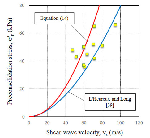
    [39] L'Heureux JS, Long M (2017) Relationship between shear-wave velocity and geotechnical parameters for Norwegian clays. J Geotech Geoenviron Eng 143: 04017013. doi: 10.1061/(ASCE)GT.1943-5606.0001645
    [40] Andersen KH, Schjetne K (2013) Database of friction angles of sand and consolidation characteristics of sand, silt, and clay. J Geotech Geoenviron Eng 139: 1140–1155. doi: 10.1061/(ASCE)GT.1943-5606.0000839
    [41] Länsivaara (2012) Some aspects on creep and primary deformation properties of soft sensitive Scandinavian clays. In Proceedings of the 16th Nordic Geotechnical Meeting, NGM, Copenhagen, Denmark, 9–12.
    [42] Janbu N (1963) Soil compressibility as determined by oedometer and triaxial tests. In Proceeding of the European Conference on Soil Mechanics and Foundation Engineering 1: 19–25.
  • This article has been cited by:

    1. Bruno Di Buò, Marco D’Ignazio, Juha Selänpää, Tim Länsivaara, Paul W. Mayne, Yield stress evaluation of Finnish clays based on analytical piezocone penetration test (CPTu) models, 2020, 57, 0008-3674, 1623, 10.1139/cgj-2019-0427
    2. Jean-Sebastien L’Heureux, Tom Lunne, Characterization and Engineering properties of Natural Soils used for Geotesting, 2020, 6, 2471-2132, 35, 10.3934/geosci.2020004
    3. Mike Long, Marco D’Ignazio, Shear wave velocity as a tool for characterising undrained shear strength of Nordic clays, 2021, 710, 1755-1307, 012008, 10.1088/1755-1315/710/1/012008
    4. Gerardo W Quirós, Patricia M Peters, Kuat C Gan, Combining NSP- and CPTu-based Nkt to evaluate undrained shear strength, 2023, 9, 2471-2132, 95, 10.3934/geosci.2023007
    5. Mark Abelev, Igor Averin, Alexander Levchenko, Dmitry Chunyuk, Olga Kopteva, 2023, 2759, 0094-243X, 040025, 10.1063/5.0130181
    6. Yunrui Han, Li Cheng, Long Yu, Qing Yang, Yubin Ren, Boundary effect on the soil strength estimation from T-bar penetration tests, 2024, 150, 01411187, 104107, 10.1016/j.apor.2024.104107
    7. Luisa Dhimitri, John J.M. Powell, A. Viana da Fonseca, C. Ferreira, Constrained modulus of fine-grained soils from in situ-based correlations and comparison with laboratory tests, 2024, 544, 2267-1242, 17003, 10.1051/e3sconf/202454417003
    8. Emílio Graciliano Ferreira Mercuri, Toomas Tamm, Steffen Manfred Noe, Water and carbon balances in a hemi-boreal forest, 2023, 78, 1736-8723, 72, 10.2478/fsmu-2023-0006
  • Reader Comments
  • © 2019 the Author(s), licensee AIMS Press. This is an open access article distributed under the terms of the Creative Commons Attribution License (http://creativecommons.org/licenses/by/4.0)
通讯作者: 陈斌, bchen63@163.com
  • 1. 

    沈阳化工大学材料科学与工程学院 沈阳 110142

  1. 本站搜索
  2. 百度学术搜索
  3. 万方数据库搜索
  4. CNKI搜索

Metrics

Article views(5648) PDF downloads(865) Cited by(8)

Figures and Tables

Figures(20)  /  Tables(4)

/

DownLoad:  Full-Size Img  PowerPoint
Return
Return

Catalog