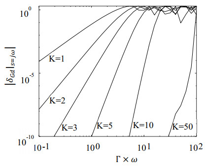
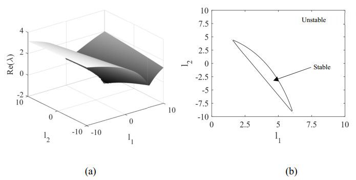
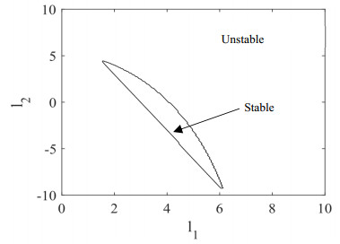
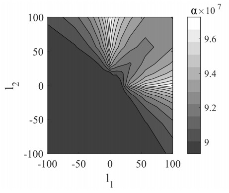
This paper developed an observer design for a matrix-Lipchitz nonlinear system with measurement delay that can achieve a desired $ {\mathcal{L}}_{2} $ performance in the presence of modeling uncertainties, input disturbance, and measurement noise. The observer was shown to be stable in the absence of disturbances and modeling uncertainties. The equations for the observer design were shown to be both necessary and sufficient. Furthermore, the observer design was formulated as linear matrix inequality (LMI) that can be solved offline using commercial solvers. Compared to previous literature, the proposed observer does not require the underlying system to be stable. The observer design procedure is demonstrated through two illustrative examples.
Citation: Krishna Vijayaraghavan. Robust-observer design for nonlinear systems with delayed measurements using time-averaged Lyapunov stability criterion[J]. Electronic Research Archive, 2025, 33(6): 3857-3882. doi: 10.3934/era.2025171
This paper developed an observer design for a matrix-Lipchitz nonlinear system with measurement delay that can achieve a desired $ {\mathcal{L}}_{2} $ performance in the presence of modeling uncertainties, input disturbance, and measurement noise. The observer was shown to be stable in the absence of disturbances and modeling uncertainties. The equations for the observer design were shown to be both necessary and sufficient. Furthermore, the observer design was formulated as linear matrix inequality (LMI) that can be solved offline using commercial solvers. Compared to previous literature, the proposed observer does not require the underlying system to be stable. The observer design procedure is demonstrated through two illustrative examples.

| [1] | Y. Song, K. Zhao, H. Ye, Control of Nonlinear Systems: Stability and Performance, CRC Press, 2024. https://doi.org/10.1201/9781003474364 |
| [2] | J. Xu, Nonlinear Dynamics of Time Delay Systems: Methods and Applications, Springer, 2024. https://doi.org/10.1007/978-981-99-9907-1 |
| [3] |
R. Majeed, S. Ahmad, M. Rehan, Delay-range-dependent observer-based control of nonlinear systems under input and output time-delays, Appl. Math. Comput., 262 (2015), 145-159. https://doi.org/10.1016/j.amc.2015.04.052 doi: 10.1016/j.amc.2015.04.052

|
| [4] |
Q. He, J. Liu, Sliding mode observer for a class of globally Lipschitz non-linear systems with time-varying delay and noise in its output, IET Control Theory Appl., 8 (2014), 1328-1336. https://doi.org/10.1049/iet-cta.2013.1004 doi: 10.1049/iet-cta.2013.1004
|
| [5] |
Q. He, J. Liu, Observer-based stabilisation of a class of nonlinear systems in the presence of measurement delay, Int. J. Control, 89 (2015), 1180-1190. https://doi.org/10.1080/00207179.2015.1125021 doi: 10.1080/00207179.2015.1125021
|
| [6] |
K. Vijayaraghavan, A. Valibeygi, Adaptive nonlinear observer for state and unknown parameter estimation in noisy systems, Int. J. Control, 89 (2015), 35-84. https://doi.org/10.1080/00207179.2015.1057231 doi: 10.1080/00207179.2015.1057231
|
| [7] |
Y. Dong, H. Wang, Y. Wang, Design of observers for nonlinear systems with H∞ performance analysis, Math. Methods Appl. Sci., 37 (2014), 718-725. https://doi.org/10.1002/mma.2830 doi: 10.1002/mma.2830
|
| [8] | S. S. Delshad, T. Gustafsson, H. R. Karimi, A. Zemouche, Observer-based control design for a class of nonlinear systems subject to unknown inputs: LMI approach, in 2015 15th International Conference on Control, Automation and Systems (ICCAS), IEEE, (2015), 984-989. https://doi.org/10.1109/ICCAS.2015.7364768 |
| [9] |
K. Vijayaraghavan, Nonlinear observer for simultaneous states and unknown parameter estimation, Int. J. Control, 86 (2013), 2263-2273. https://doi.org/10.1080/00207179.2013.811291 doi: 10.1080/00207179.2013.811291
|
| [10] |
A. Zemouche, R. Rajamani, H. Kheloufi, F. Bedouhene, Robust observer-based stabilization of Lipschitz nonlinear uncertain systems via LMIs - discussions and new design procedure, Int. J. Robust Nonlinear Control, 27 (2017), 1915-1939. https://doi.org/10.1002/rnc.3644 doi: 10.1002/rnc.3644
|
| [11] |
R. Rajamani, Observers for Lipschitz nonlinear systems, IEEE Trans. Autom. Control, 43 (1998), 397-401. https://doi.org/10.1109/9.661604 doi: 10.1109/9.661604
|
| [12] |
R. Rajamani, Y. M. Cho, Existence and design of observers for nonlinear systems: Relation to distance to unobservability, Int. J. Control, 69 (1998), 717-731. https://doi.org/10.1080/002071798222640 doi: 10.1080/002071798222640
|
| [13] |
F. Zhu, Z. Han, A note on observers for Lipschitz nonlinear systems, IEEE Trans. Autom. Control, 47 (2002), 1751-1754. https://doi.org/10.1109/TAC.2002.803552 doi: 10.1109/TAC.2002.803552
|
| [14] |
A. Zemouche, M. Boutayeb, G. I. Bara, Observers for a class of Lipschitz systems with extension to H∞ performance analysis, Syst. Control Lett., 57 (2008), 18-27. https://doi.org/10.1016/j.sysconle.2007.06.012 doi: 10.1016/j.sysconle.2007.06.012
|
| [15] |
J. Huang, Z. Han, X. Cai, L. Liu, Adaptive full-order and reduced-order observers for the Lur'e differential inclusion system, Commun. Nonlinear Sci. Numer. Simul., 16 (2011), 2869-2879. https://doi.org/10.1016/j.cnsns.2010.09.036 doi: 10.1016/j.cnsns.2010.09.036
|
| [16] | G. Phanomchoeng, R. Rajamani, Observer design for Lipschitz nonlinear systems using Riccati equations, in Proceedings of the American Control Conference ACC 2010, IEEE, (2010), 6060-6065. https://doi.org/10.1109/ACC.2010.5531294 |
| [17] |
G. Phanomchoeng, R. Rajamani, D. Piyabongkarn, Nonlinear observer for bounded Jacobian systems, with applications to automotive slip angle estimation, IEEE Trans. Autom. Control, 56 (2011), 1163-1170. https://doi.org/10.1109/TAC.2011.2108552 doi: 10.1109/TAC.2011.2108552
|
| [18] |
R. Rajamani, A. Ganguli, Sensor fault diagnostics for a class of non-linear systems using linear matrix inequalities, Int. J. Control, 77 (2004), 920-930. https://doi.org/10.1080/00207170412331270523 doi: 10.1080/00207170412331270523
|
| [19] |
K. Vijayaraghavan, R. Rajamani, J. Bokor, Quantitative fault estimation for a class of non-linear systems, Int. J. Control, 80 (2007), 64-74. https://doi.org/10.1080/00207170600921029 doi: 10.1080/00207170600921029
|
| [20] | J. Lei, H. K. Khalil, High-gain observers in the presence of sensor nonlinearities, in 2017 American Control Conference (ACC), IEEE, (2017), 3282-3287. https://doi.org/10.23919/ACC.2017.7963453 |
| [21] | H. K. Khalil, High-Gain Observers in Nonlinear Feedback Control, SIAM, 2017. https://doi.org/10.1137/1.9781611974867 |
| [22] |
H. K. Khalil, L. Praly, High-gain observers in nonlinear feedback control, Int. J. Robust Nonlinear Control, 24 (2014), 993-1015. https://doi.org/10.1002/rnc.3051 doi: 10.1002/rnc.3051
|
| [23] | S. Mehta, K. Vijayaraghavan, Analysis of sliding mode observers using a novel time-averaged Lyapunov function, in Proceedings of the ASME 2017 International Design Engineering Technical Conferences and Computers and Information in Engineering Conference, American Society of Mechanical Engineers, (2017), 1-9. https://doi.org/10.1115/DETC2017-68131 |
| [24] |
S. Mehta, K. Vijayaraghavan, Design of sliding observers for Lipschitz nonlinear system using a new time-averaged Lyapunov function, Int. J. Control, 92 (2019), 2420-2429. https://doi.org/10.1080/00207179.2018.1441551 doi: 10.1080/00207179.2018.1441551
|
| [25] |
M. Ran, J. Li, L. Xie, A new extended state observer for uncertain nonlinear systems, Automatica, 131 (2021), 109772. https://doi.org/10.1016/j.automatica.2021.109772 doi: 10.1016/j.automatica.2021.109772
|
| [26] |
J. C. L. Chan, T. H. Lee, C. P. Tan, H. Trinh, J. H. Park, A nonlinear observer for robust fault reconstruction in one-sided Lipschitz and quadratically inner-bounded nonlinear descriptor systems, IEEE Access, 9 (2021), 22455-22469. https://doi.org/10.1109/ACCESS.2021.3056136 doi: 10.1109/ACCESS.2021.3056136
|
| [27] |
Y. Batmani, H. Khaloozadeh, On the design of observer for nonlinear time-delay systems, Asian J. Control, 16 (2014), 1191-1201. https://doi.org/10.1002/asjc.795 doi: 10.1002/asjc.795
|
| [28] |
H. Trinh, M. Aldeen, S. Nahavandi, An observer design procedure for a class of nonlinear time-delay systems, Comput. Electr. Eng., 30 (2004), 61-71. https://doi.org/10.1016/S0045-7906(03)00037-5 doi: 10.1016/S0045-7906(03)00037-5
|
| [29] |
W. Chen, D. Li, X. Lu, Impulsive observers with variable update intervals for Lipschitz nonlinear time-delay systems, Int. J. Syst. Sci., 44 (2013), 1934-1947. https://doi.org/10.1080/00207721.2012.670305 doi: 10.1080/00207721.2012.670305
|
| [30] | I. Karafyllis, M. Malisoff, F. Mazenc, P. Pepe, Recent Results on Nonlinear Delay Control Systems, Springer, 2016. https://doi.org/10.1007/978-3-319-18072-4 |
| [31] |
S. Lin, J. Yuan, Z. Liu, T. Zhou, A. Li, C. Gu, et al., Distributionally robust parameter estimation for nonlinear fed-batch switched time-delay system with moment constraints of uncertain measured output data, Electron. Res. Arch., 32 (2024), 5889-5913. https://doi.org/10.3934/era.2024272 doi: 10.3934/era.2024272
|
| [32] |
J. Li, J. Yan, H. Zhang, K. Xiao, Identification of feedback nonlinear systems with time delay based on chaotic decreasing weight sparrow search algorithm, Soft Comput., 28 (2024), 4009-4024. https://doi.org/10.1007/s00500-023-09373-5 doi: 10.1007/s00500-023-09373-5
|
| [33] |
B. Liu, W. Chen, Time delay and model parameter estimation for nonlinear system with simultaneous approach, J. Process Control, 139 (2024), 103234. https://doi.org/10.1016/j.jprocont.2024.103234 doi: 10.1016/j.jprocont.2024.103234
|
| [34] |
J. Zhou, J. H. Park, Q. Ma, Non-fragile observer-based H∞ control for stochastic time-delay systems, Appl. Math. Comput., 291 (2016), 69-83. https://doi.org/10.1016/j.amc.2016.06.024 doi: 10.1016/j.amc.2016.06.024
|
| [35] |
N. Kazantzis, R. A. Wright, Nonlinear observer design in the presence of delayed output measurements, Syst. Control Lett., 54 (2005), 877-886. https://doi.org/10.1016/j.sysconle.2004.12.005 doi: 10.1016/j.sysconle.2004.12.005
|
| [36] |
F. Cacace, A. Germani, C. Manes, An observer for a class of nonlinear systems with time varying observation delay, Syst. Control Lett., 59 (2010), 305-312. https://doi.org/10.1016/j.sysconle.2010.03.005 doi: 10.1016/j.sysconle.2010.03.005
|
| [37] |
A. Vafaei, M. J. Yazdanpanah, A chain observer for nonlinear long constant delay systems: A matrix inequality approach, Automatica, 65 (2016), 164-169. https://doi.org/10.1016/j.automatica.2015.11.012 doi: 10.1016/j.automatica.2015.11.012
|
| [38] |
A. Chakrabarty, E. Fridman, S. H. Żak, G. T. Buzzard, State and unknown input observers for nonlinear systems with delayed measurements, Automatica, 95 (2018), 246-253. https://doi.org/10.1016/j.automatica.2018.05.036 doi: 10.1016/j.automatica.2018.05.036
|
| [39] |
D. C. Huong, A fresh approach to the design of observers for time-delay systems, Trans. Inst. Meas. Control, 40 (2016), 477-503. https://doi.org/10.1177/0142331216661758 doi: 10.1177/0142331216661758
|
| [40] |
B. Targui, O. Hernández-González, C. M. Astorga-Zaragoza, G. V. Guerrero-Ramírez, M. E. Guerrero-Sánchez, A new observer design for systems in presence of time-varying delayed output measurements, Int. J. Control Autom. Syst., 17 (2019), 117-125. https://doi.org/10.1007/s12555-017-0224-x doi: 10.1007/s12555-017-0224-x
|
| [41] |
M. Guarro, F. Ferrante, R. G. Sanfelice, A hybrid observer for linear systems under delayed sporadic measurements, Int. J. Robust Nonlinear Control, 34 (2024), 6610-6635. https://doi.org/10.1002/rnc.7213 doi: 10.1002/rnc.7213
|
| [42] |
S. Bououden, F. Allouani, A. Abboudi, M. Chadli, I. Boulkaibet, Z. A. Barakeh, et al., Observer-based robust fault predictive control for wind turbine time-delay systems with sensor and actuator faults, Energies, 16 (2023), 858. https://doi.org/10.3390/en16020858 doi: 10.3390/en16020858
|
| [43] |
Z. Li, G. Cao, W. Xie, R. Gao, W. Zhang, Switched-observer-based adaptive neural networks tracking control for switched nonlinear time-delay systems with actuator saturation, Inf. Sci., 621 (2023), 36-57. https://doi.org/10.1016/j.ins.2022.11.094 doi: 10.1016/j.ins.2022.11.094
|
| [44] |
E. Fridman, Tutorial on Lyapunov-based methods for time-delay systems, Eur. J. Control, 20 (2014), 271-283. https://doi.org/10.1016/j.ejcon.2014.10.001 doi: 10.1016/j.ejcon.2014.10.001
|
| [45] | S. Boyd, L. E. Ghaoui, E. Feron, V. Balakrishnan, Linear Matrix Inequalities in System and Control Theory SIAM Studies in Applied Mathematics, SIAM, 1994. https://doi.org/10.1137/1.9781611970777 |
| [46] | H. K. Khalil, Nonlinear Systems, 3rd Edition, Prentice Hall, 2002. |
| [47] | M. A. Woodbury, Inverting Modified Matrices, Princeton University, 1950. |
| [48] | M. Vajta, Some remarks on Padé-approximations, in 3rd TEMPUS-INTCOM Symposium on Intelligent Systems in Control and Measurements 2000, (2000), 53-58. |
| [49] |
E. Fridman, U. Shaked, Delay-dependent stability and H∞ control: Constant and time-varying delays, Int. J. Control, 76 (2003), 48-60. https://doi.org/10.1080/0020717021000049151 doi: 10.1080/0020717021000049151
|
| [50] |
P. Park, J. W. Ko, C. Jeong, Reciprocally convex approach to stability of systems with time-varying delays, Automatica, 47 (2011), 235-238. https://doi.org/10.1016/j.automatica.2010.10.014 doi: 10.1016/j.automatica.2010.10.014
|
Figures(8)
Krishna Vijayaraghavan. Robust-observer design for nonlinear systems with delayed measurements using time-averaged Lyapunov stability criterion[J]. Electronic Research Archive, 2025, 33(6): 3857-3882. doi: 10.3934/era.2025171


 DownLoad: